Table of Contents
Advertisement
Installation, Operation, and Maintenance Manual
IF YOU SMELL GAS: OPEN WINDOWS, DO NOT TOUCH ELECTRICAL SWITCHES, EXTINGUISH
ANY OPEN FLAMES, IMMEDIATELY CALL YOUR GAS SUPPLIER.
THE USE AND STORAGE OF GASOLINE OR OTHER FLAMMABLE VAPORS AND LIQUIDS IN
OPEN CONTAINERS IN THE VICINITY OF THIS APPLIANCE IS HAZARDOUS.
Upon receiving unit, check for any interior and exterior damage. If damage is found, report it
immediately to the carrier. Check that all accessory items are accounted for and are not
damaged.
Improper installation, adjustment, alteration, service or maintenance can cause property
damage, injury or death. Read the installation, operating and maintenance instructions
thoroughly before installing or servicing this equipment. ALWAYS disconnect power and gas
prior to working on heater.
Save these instructions. This document is the property of the owner of this equipment and is required
for future maintenance. Leave this document with the owner when installation or service is complete.
FOR YOUR SAFETY
FOR YOUR SAFETY
RECEIVING AND INSPECTION
WARNING!!
Compact Direct Fired Heaters
May 2020 Rev. 15
A0011029
Advertisement
Table of Contents
Troubleshooting

Summary of Contents for CaptiveAire D76
- Page 1 Compact Direct Fired Heaters Installation, Operation, and Maintenance Manual FOR YOUR SAFETY IF YOU SMELL GAS: OPEN WINDOWS, DO NOT TOUCH ELECTRICAL SWITCHES, EXTINGUISH ANY OPEN FLAMES, IMMEDIATELY CALL YOUR GAS SUPPLIER. FOR YOUR SAFETY THE USE AND STORAGE OF GASOLINE OR OTHER FLAMMABLE VAPORS AND LIQUIDS IN OPEN CONTAINERS IN THE VICINITY OF THIS APPLIANCE IS HAZARDOUS.
-
Page 3: Table Of Contents
Table of Contents WARRANTY ..................................... 4 INSTALLATION ..................................5 Mechanical ................................... 5 Curb and Ductwork ................................7 Roof Mount Installation ................................. 8 Gas ....................................... 9 ELECTRICAL ..................................11 Fan to Building Wiring Connection ............................. 12 Motorized Intake Damper ............................... 13 Permanent Split Capacitor (PSC) Motor Speed Control .................... -
Page 4: Warranty
WARRANTY This equipment is warranted to be free from defects in materials and workmanship, under normal use and service, for a period of 2-years from date of shipment. This warranty shall not apply if: 1. The equipment is not installed by a qualified installer per the MANUFACTURER’S installation instructions shipped with the product. -
Page 5: Installation
INSTALLATION It is imperative that this unit is installed and operated with the designed airflow and electrical supply in accordance with this manual. If there are any questions about any items, please call the service department at 1-866-784-6900 for warranty and technical support issues. Mechanical WARNING: DO NOT RAISE UNIT BY THE INTAKE HOOD, BLOWER, MOTOR SHAFT, OR BEARINGS. - Page 6 Intake Assembly Intakes and curbs (Figure 2) are shipped on a separate skid. Upon unit arrival, perform the following steps to assemble the intake to the unit. 1. Apply silicone or weather-proof gasket on the backside of the flanges of the intake hood or V-bank intake.
-
Page 7: Curb And Ductwork
Curb and Ductwork This fan was specified for a specific CFM and static pressure. The ductwork attached to this unit will significantly affect airflow performance. When using rectangular ductwork, elbows must be radius throat, radius back with turning vanes. Flexible ductwork and square throat/square back elbows should not be used. -
Page 8: Roof Mount Installation
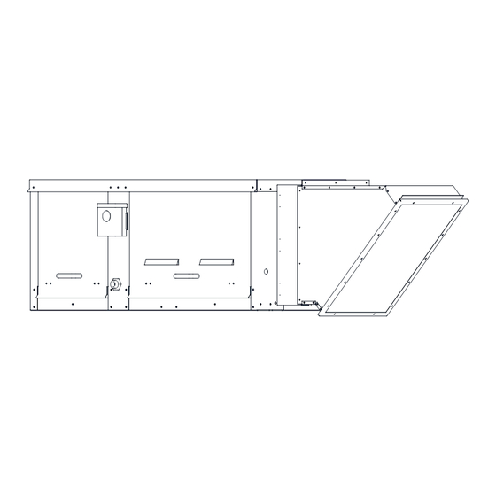
Roof Mount Installation Note: Refer to submittal drawings for specific unit dimensions. Figure 3 - Roof Mount Installation Details 1. Discharge Opening 2. Curb Outer Wall 3. Flex Conduit for Field Wiring 4. Screened Intake AIRFLOW 5. Filter Access Door 6. -
Page 9: Gas
Installation of gas piping must conform with local building codes, or in the absence of local codes to the National Fuel Gas Code, ANSI Z223.1 (NFPA 54) – latest edition. In Canada, installation must be in accordance with CAN/CGA-B149.1 for natural gas units and CAN/CGA-B149.2 for propane units. WARNING: INLET GAS PRESSURE MUST NOT EXCEED PRESSURE INDICATED ON NAMEPLATE. - Page 10 Figure 5 - Gas Connection Diagram 1. Gas Supply Line Connection 4. Plugged 1/8” NPT Test Gauge Connection 2. Manual Gas Shut-off Valve 5. Sediment Trap 3. Ground Joint Union with Brass Seat A. Minimum Depth = 3” Table 3 - Gas Pressure Gas Pressure Type Gas Pressure Natural/LP...
-
Page 11: Electrical
ELECTRICAL WARNING!! Disconnect power before installing or servicing unit. High voltage electrical input is needed for this equipment. A qualified electrician should perform this work. Before connecting power to the heater, read and understand the entire section of this document. As-built wiring diagrams are furnished with each unit by the factory and are attached to the control module’s door or provided with paperwork packet. -
Page 12: Fan To Building Wiring Connection
Fan to Building Wiring Connection Figure 6 - Wiring Connection Details Single Point Connection 120V 1 PH. 208-240V 1 PH. 208-240/460/600V 3 PH. WIRE COLOR BK - BLACK RD - RED BK BK WH - WHITE GR - GREEN 1. Disconnect Switch 3. -
Page 13: Motorized Intake Damper
Permanent Split Capacitor (PSC) Motor Speed Control Figure 7 - PSC Motor Speed Control Some single-phase direct-drive fans contain speed controls that regulate the amount of voltage going to the motor. Specific PSC Vari-Speed motors must be used in conjunction with speed controls. The speed control has a knob (Figure 7) with an off position along with high to low range. -
Page 14: Electronically Commutated Motor (Ecm) Speed Control
Electronically Commutated Motor (ECM) Speed Control An Electrically Commutated Motor (ECM) with speed control allows for an accurate manual adjustment of the fan’s speed. The benefits of using an EC motor is exceptional efficiency, performance, and motor life. External PWM Signal The fan unit will be shipped with power wiring and communication wiring fed to an internal junction box. -
Page 15: Motor Speed Controller (Msc) Installation
Motor Speed Controller (MSC) Installation The Motor Speed Controller (MSC) is a versatile device able to output various signal types to many different Electrically Commutated Motors (ECMs). The MSC signal output types can be selected under the ‘Motor Type’ section of the MSC menu. The MSC may be installed in a fan, remotely in a kitchen space, or in a mechanical room. -
Page 16: Msc Controls Overview
MSC Controls Overview There are four buttons to navigate through the menu screens, refer to Figure 10. Press the MENU button to access menu settings/parameters, pressing MENU will also back out of the current menu screen. To scroll through menus, use UP and DOWN buttons. Press the ENTER button to change setting/parameter selection. - Page 17 • Modbus # - Adjustable Modbus ID. Exhaust Fan range 11-18, Supply Fan range 21 or 22. A VFD and MSC cannot use the same Modbus #. • Options • Feedback Fault - If set to ENABLED, the MSC will monitor RPM feedback. If the MSC does not receive data for 30 seconds or 70% of the expected RPM, this fault will be displayed.
-
Page 18: Input Threshold
Input Threshold Figure 11 - Input Threshold Examples Factory Default: Zero operation set to low speed, threshold set to 0V. HIGH SPEED 0-10V INPUT DEVICE OUTPUT 0-10V OR PWM OUTPUT SIGNAL DEPENDANT ON SETTINGS OPERATING BAND SPEED INPUT VOLTS Zero operation set to low speed, threshold set to 2V. HIGH SPEED 0-10V INPUT 0-10V OR PWM... -
Page 19: Msc Menu Tree
MSC Menu Tree RANGE: NIDEC, TELCO 42, TELCO 48 (DEFAULT), MOTOR TYPE ZIEHL, 0-10V, OTHER RANGE: LOCAL (DEFAULT), CONTROL TYPE REMOTE MODBUS, REMOTE 0-10V RANGE: 20%-100% or 0-10V SPEED SETTING LOW SPEED DEFAULT: 20% or 0V RANGE: 20%-100% or 0-10V HIGH SPEED DEFAULT: 100% or 10V RANGE: 20%-100% or 0-10V... -
Page 20: Remote Control Panel
Remote Control Panel On units shipped with the optional remote control panel, an electrical drop containing the panel wiring is provided with the heater. There is a terminal strip inside the remote panel that matches the terminals in the heater unit. The remote panel should be wired as shown in Figure 12. Wiring may vary by unit, refer to electrical schematics that were provided with your unit. -
Page 21: Variable Frequency Drive (Vfd)
Variable Frequency Drive (VFD) WARNING!! - Before installing the VFD drive, ensure the input power supply to the drive is OFF. - The power supply and motor wiring of the VFD must be completed by a qualified electrician. - The VFD is factory programmed, only change if replaced or ordered separately. Consult the VFD manual and all documentation shipped with the unit for proper installation and wiring of the VFD. -
Page 22: Variable Frequency Drive (Vfd) Installation
Variable Frequency Drive (VFD) Installation Input AC Power • Circuit breakers feeding the VFDs are recommended to be thermal-magnetic and fast-acting. They should be sized based on the VFD amperage and according to Table 6 on page 24. Refer to the installation schematic for exact breaker sizing. -
Page 23: Vfd Programming
VFD Programming Programming 1. The Drive should be programmed for the proper motor voltage. P107 is set to 0 (Low) if motor voltage is 120V AC, 208V AC or 400V AC. P107 is set to 1 (High) if the motor voltage is 230V AC, 480V AC, or 575V AC. -
Page 24: Actech Smv Vfd
ACTECH SMV VFD Table 6 - Cross Reference 1Ø 3Ø Input Amps 1Ø Input Amps 1Ø Output Breaker 1Ø Breaker 1Ø Part Number Volts Input Input 120V AC 240V AC Amps 120V AC 240V AC ESV371N01SXB 120/240V ESV751N01SXB 120/240V 16.6 ESV112N01SXB 120/240V 1Ø... -
Page 25: Operation
START-UP OPERATION Before starting up or operating the unit, verify all fasteners are secure and tight. Check the set screw in the wheel hub, bearings, and the fan sheaves (pulleys). With power and gas OFF to the unit or before connecting the unit to power, turn the fan wheel by hand. -
Page 26: Pilot Adjustment
Pilot Adjustment 1. Restart the fan and check the gas supply pressure at the inlet gas gauge upstream of all electronic valves. The inlet pressure should be 5-14 inches wc. If the inlet pressure is too high, install an additional pressure regulator external to the unit. 2. -
Page 27: Main Burner Adjustment
Main Burner Adjustment 1. Once the pilot has been properly established, the manifold gas pressure or temperature rise should be adjusted to nameplate or design specifications. The gas pressure regulator is adjusted at the factory for average gas conditions. It is important that the gas supplied to the burner is in accordance with the input rating on the rating plate. -
Page 28: Final Start-Up Procedure
Figure 16 - Pressure vs. Firing Rate Average Manifold Pressure vs. Firing Rate/Ft. of Burner 6.00 5.00 Natural 4.00 Propane 3.00 2.00 1.00 0.00 -1.00 100000 200000 300000 400000 500000 600000 Firing Rate (BTU/Hr/Ft. of Burner) Final Start-up Procedure 1. With the air and burner systems in full operation and all ducts attached, measure the system airflow. The motor sheave (pulley) is variable pitch and allows for an increase or decrease of the fan RPM. -
Page 29: Pulley Adjustment
Pulley Adjustment The adjustable motor pulley is factory set for the RPM specified (Table 7). Speed can be increased by closing or decreased by opening the adjustable motor sheave. Two groove variable pitch pulleys must be adjusted to an equal number of turns open or closed. Any increase in speed represents a substantial increase in horsepower required by the unit. -
Page 30: Pulley Alignment/Proper Belt Tension
Pulley Alignment/Proper Belt Tension 1. Belts tend to stretch and settle into pulleys after an initial start-up sequence. Do not tension belts by changing the setting of the motor pulley, this will change the fan speed and may damage the motor. •... -
Page 31: Pulley Combination Chart
Pulley Combination Chart Table 8 - 7” Blower Pulley Chart Motor RPM 1725 1/3 to 1-1/2 HP MOTOR PULLEY Dd1 Dd2 Pd1 Pd2 AX BELTS 1VP50 Open TURNS ON MOTOR PULLEY Closed DATUM PITCH BLOWER PULLEY 4 1/2 3 1/2 2 1/2 1 1/2 DIAMETER... -
Page 32: Sequence Of Operation
Sequence of Operation To better understand the heater, it is easier to break the unit out into smaller individual systems. There are two main systems, a make-up air fan, and a heater. The make-up air fan consists of a blower and motor. The heater may be further broken down into two control systems, the Flame Safety Control (FSC) and the Modulating Gas System (MGS). - Page 33 Air Flow Switch Figure 20 - Air Flow Switch There are both high and low airflow switches contained within one housing (Figure 20) measuring the pressure drop across the burner. This is to ensure that there is proper airflow (.15 inches wc to .80 inches wc) across the burner and proper combustion at all times.
-
Page 34: Modulating Gas System
Modulating Gas System The second system, the modulating gas system, consists of a temperature selector dial, a discharge air sensor, an amplifier, and a modulating gas valve. The two types of modulating gas systems used are the Maxitrol 14 or RTC Solutions controls and the Maxitrol 44 series. The Maxitrol 14/RTC utilizes a discharge air sensor and modulates the Maxitrol gas valve to provide discharge air to match the selected temperature on the temperature selector. -
Page 35: Optional Remote Panel Circuit
Optional Remote Panel Circuit Power Supply From Heater No Power to "Power" Light Panel Panel is Powered Nothing Happens "Off" Blower Switch Position No Power is Sent (3-Position Panels Only) to Heater "Auto" "Manual" Power is Sent to Power is Sent to Heater to Open Heater to Open Damper (if... -
Page 36: Remote Panel Option
Remote Panel Option The remote panel is a device used to control the operation of the heater from a remote location. This unit is available in both a “2 Position” and “3 Position” configuration, and with or without a cooling output. It also will accommodate both discharge and space heating configurations. -
Page 37: Troubleshooting
Troubleshooting The following table lists causes and corrective actions for possible problems with the fan units. Review this list prior to consulting manufacturer. The following table lists causes and corrective actions for possible problems with the fan units. Review this list before consulting manufacturer. Airflow Troubleshooting Chart Problem Potential Cause... -
Page 38: Burner Troubleshooting
Burner Troubleshooting Table 9 - Burner Troubleshooting Chart Problem Potential Cause Corrective Action Main gas is off Open main gas valve. Air in gas line Purge gas line. Dirt in pilot orifice Clean orifice with compressed air. Gas pressure out of range Adjust to proper gas pressure. -
Page 39: Remote Panel Troubleshooting Chart
Remote Panel Troubleshooting Chart Table 10 - Troubleshooting Chart Light Indication Condition Possible Cause No Lights Power not available to remote panel Incorrect voltage to unit. Main disconnect switch in “OFF” position. Circuit breaker tripped. Faulty main transformer. Power Light Only Proper unit - Off operation No correction required. -
Page 40: Msc Troubleshooting
MSC Troubleshooting Fault Problem Potential Cause Corrective Action Secure connections to Disconnected/faulty fan. If faulty wiring is wiring found, repair or replace as required. Feedback Fault on Feedback Fault MSC Display No feedback for 30 Check parameters seconds Check duct/fan for Less than 70% of RPM obstructions. -
Page 41: Maintenance
MAINTENANCE To guarantee trouble-free operation of this heater, the manufacturer suggests following these guidelines. Most problems associated with fan failures are directly related to poor service and maintenance. Please record any maintenance or service performed on this fan in the documentation section located at the end of this manual. -
Page 42: Burner Maintenance
Table 11 - Filter Quantity Chart Intake 16” x 20” Burner Maintenance 1. Verify the unit is off. 2. Inspect the pilot assembly, refer to “Pilot Assembly” on page 26. Replace if required. 3. Inspect the burner plates. 4. Clean the burner plates. Make sure the baffles are secure and attached to the burner. 5. - Page 43 Notes...
-
Page 44: Start-Up And Maintenance Documentation
Start-Up and Maintenance Documentation START-UP AND MEASUREMENTS SHOULD BE PERFORMED AFTER THE SYSTEM HAS BEEN AIR BALANCED AND WITH THE HEAT ON (Warranty will be void without completion of this form) Job Information Job Name Service Company Address Address City City State State...
Need help?
Do you have a question about the D76 and is the answer not in the manual?
Questions and answers