Advertisement
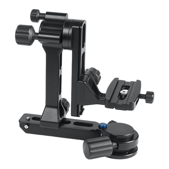
Please read these instructions to fully understand the functions and capabilities of your new G1 Gimbal head.
Included in package:
G1 Gimbal head
1 packet of spare screws containing
2- ¼-20 x ¾ Flat head patch screws
1- ⅜-16 x ¾ Low head cap screw
10 YEAR GUARANTEE
This product is guaranteed to the original purchaser to
be free of defects in materials or workmanship for ten
years from the date of purchase. Products will be
repaired or replaced at our option.
If not purchased directly from Kirk Enterprise Solutions,
please keep your original receipt for warranty repair as
proof of purchase of original ownership will be required.
Please note
All knobs are captive, meaning they cannot come off
without damaging them. Do not attempt to remove the
knobs. This will damage the head and void the warranty.
Also the G1 head is lubricated at the factory and parts
that require lubrication are sealed. NO LUBRICATION IS
REQUIRED BY THE USER. Just keep the G1
components free from contamination to maintain smooth
action.
Kirk Enterprise Solutions 333 Hoosier Dr Angola In 46703
www.kirkphoto.com
260-665-3670
Advertisement
Table of Contents

Summary of Contents for KES G1
- Page 1 Please read these instructions to fully understand the functions and capabilities of your new G1 Gimbal head. Included in package: G1 Gimbal head 1 packet of spare screws containing 2- ¼-20 x ¾ Flat head patch screws 1- ⅜-16 x ¾ Low head cap screw...
- Page 2 Tilt axis tension knob B- Tilt axis lock knob C- Panning lock knob D- Panning tension knob E- Quick release platform adjustment knob F- Side arm adjustment knob G- Spring loaded safety pin H- Spring loaded pan base locking pin I- Quick release clamp placement adjustment screw J- Arca Style quick release clamp K- Quick release mounting platform...
- Page 3 (A) this will help you achieve this quickly. Step 4 The G1 gimbal head is designed with the ability to apply tension of the tilt axis and pan axis from knobs (A) and (D). To achieve this, you will slightly turn the desired knob clockwise for more tension or counterclockwise for less tension.
- Page 4 Step 5 Mounting and balancing your lens combination will be similar to Step 3 on the Gimbal top mount head set up page Figure 1 Side mount The G1 Gimbal head, when set up as a side mount gimbal, all knobs and spring loaded pins will Gimbal head function as they did as the top mount gimbal head. completed...
- Page 5 G1 Gimbal disassembly for storage Step 1 Loosen quick release platform adjustment knob (E) and slide the quick release mounting platform (K) to the top and remove off the vertical rail (M). Step 2 Loosen slide arm adjustment knob (F) and slide the gimbal vertical arm (L) to the end of the gimbal horizontal base (O).
Need help?
Do you have a question about the G1 and is the answer not in the manual?
Questions and answers