Advertisement
Cardax FT Controller 3000
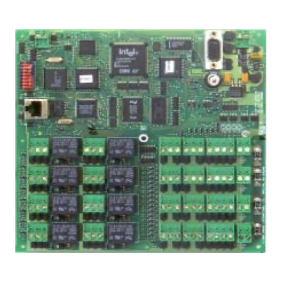
The Cardax FT Controller 3000
The Cardax FT Controller 3000 is a network compatible device that interfaces Cardax IV and
Wiegand readers into the Cardax FT Command Centre system.
The Cardax FT Controller 3000 integrates much of the functionality of the original Cardax FT
Controller 5000 with Reader and I/O functionality into a single product. Cardax FT Local BUS
connections are not supported.
Reader Interface
Interfaces to readers and associated I/O are set up as four distinct groups (numbered 1 to 4).
Each group is the same and provides connection to either one Wiegand or two Cardax IV
readers, and four balanced (4-state) inputs and two general purpose relay outputs capable of
switching 24 volts DC/AC, 5A resistive loads. Each group is also provided with a 12 V DC
500mA (resettable fuse) power output.
The Wiegand and Cardax IV interconnections share a common connector such that either one
Wiegand or two CardaxIV readers can be connected to each port. The following are examples
of possible combinations over the four groups:
•
•
•
Part number 3E1089 R3
March 2003
This equipment contains components that can be damaged by
electrostatic discharge. Ensure both you and the equipment are
earthed before beginning any servicing.
4 x Wiegand readers only
2 x Cardax IV + 3 x Wiegand readers
8 x Cardax IV readers only
CAUTION
Installation Note
1
Advertisement
Table of Contents

Summary of Contents for Cardax FT Controller 3000
- Page 1 The Cardax FT Controller 3000 The Cardax FT Controller 3000 is a network compatible device that interfaces Cardax IV and Wiegand readers into the Cardax FT Command Centre system. The Cardax FT Controller 3000 integrates much of the functionality of the original Cardax FT Controller 5000 with Reader and I/O functionality into a single product.
-
Page 2: Before You Begin
Refer to the enclosed Cardax FT Cabinet Installation Note (part number 3C4513) for the shipment contents despatched with the Cardax FT Cabinet. The cabinet for the Cardax FT Controller 3000 has a label on the inside back surface, indicating it has been configured specifically for this product. The cabinet can be rotated, however the door must not be re-hinged as the Run LED will not shine through the door. - Page 3 Output relays The Cardax FT Controller 3000 has eight relay outputs, (i.e. two per group), PE1 to PE4 and PF1 to PF4. Refer to the Component Layout within this Installation Note for wiring this plug. The cabling to and from this relay plug must be capable of carrying sufficient current for the device the relay is controlling.
-
Page 4: Installation
Cardax FT Cabinet. Using the 9 x M3 screws, fit the Controller PCB to the rear face of the Cardax FT Cabinet, ensuring that the rear tamper sensor aligns with the light pipe. Also ensure that the front LED lines up. -
Page 5: Component Layout
- IP address for the Controller (3000 Series) - IP address of the Server the Controller is to communicate with The Server can then send data to, and receive data from, the Cardax FT Controller 3000. Part number 3E1089 R3... - Page 6 Locate DIP switch 2 (SW2) on the Cardax FT Controller PCB. Set switch 2 to ON (closed). Switch on power to the Cardax FT Controller 3000. The red LED (D1) flashes in the following sequence: (The sequence completes fairly quickly but it is important you ensure the LED finishes indicating the “normal running”...
-
Page 7: Dip Switch Settings
Dip Switch Settings The following table shows the Dip Switch Settings. The Settings in bold specify the default startup configuration. Dip Switch Setting Meaning Controller will accept WWW connections. Controller will reject WWW connections. Initialise. On startup configuration and the IP address is deleted. - Page 8 (1s cycle) * Should an SSL key data file be lost or corrupted, requests for replacements should be made to your local Cardax office. You will need to supply the last six digits of the Cardax FT Controller MAC address.
-
Page 9: Removing The Pcb
Following full antistatic precautions, disconnect all cables from the Cardax FT Controller PCB. Remember to label each cable as you remove it. Remove the 9 x M3 securing screws that hold the PCB onto the Cardax FT Cabinet fixing standoffs. -
Page 10: Technical Specification
Connect the equipment into an outlet on a circuit different from that to which the receiver is connected. Consult the dealer or an experienced radio/TV technician for help. Changes or modifications not expressly approved by Cardax (International) Ltd could void the user’s authority to operate this equipment. 002132943...
Need help?
Do you have a question about the FT Controller 3000 and is the answer not in the manual?
Questions and answers