Table of Contents
Advertisement
Advertisement
Table of Contents

Subscribe to Our Youtube Channel
Summary of Contents for Minidso DS212
- Page 1 DS212 Mini Oscilloscope User Manual Version 1.0...
- Page 2 Contents Important Safety Information Chapter 1 DS212 Overview Chapter 2 Interface Introduction Chapter 3 Getting Started Chapter 4 Functional Overview Chapter 5 Product Inspection Chapter 6 Battery Disposal Chapter 7 Technical Support ! Warning: Warning statements identify conditions or practices that could result in injure yourself or others.
-
Page 3: General Safety Information
Safety Statement General Safety Information ● Read carefully all the following safety precautions to avoid personal injury and prevent damage to the device or any products connected to it. Failure to follow these safety instructions could result in personal injuries or risk of fire. -
Page 4: Specifications
Chapter 1 DS212 Over view Specifications Performance parameters Coupling AC DC Analog bandwidth 1MHz Maximum sampling rate 10MSa s / Analog input impedance 1MΩ Maximum input voltage ± 40V X1 probe Maximum sample memory depth Horizontal sensitivity 1uS/Div~2S/Div(in 1-2-5 sequence step) -
Page 5: Interface & Buttons
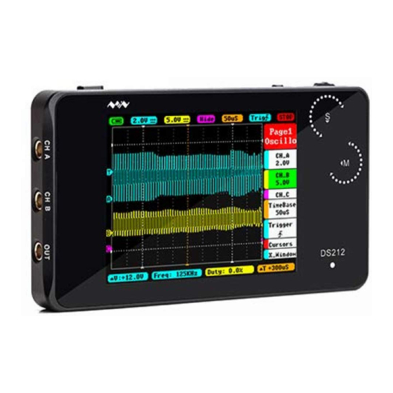
Chapter 1 DS212 Over view Interface & Buttons Left-Right Thumbwheel Power Button Run/Pause Button Up-Down Thumbwheel Charge indicator Signal Input Up-Down Thumbwheel Wave Out USB Port... - Page 6 Chapter 1 DS212 Over view Operation on option area Dial Up/Down Dial Left/Right Button Function 1)Click: Run/Pause 2)long press:Save current parameter/screen display Dial Up/Down) Choose up/down Wheel M 1)Click :Sub-menu On/Off Wheel M long press Enter file management middle button 3)Double click When "Auto Fit"...
-
Page 7: Interface Introduction
Chapter 2 Interface Introduction Home screen introduction Parameter area Option area Measurement area Home screen Measurement area introduction Menu Function △ V=V1-V2 Measured Value(Blue corresponds with Channel A, Yellow with Channel B) corresponding the 1st and 2nd item in Page2 △... - Page 8 Chapter 2 Interface Introduction Home screen introduction Option area introduction Page2(Measurement) Page1(oscilloscope) A channel option Frequency Bchannel option Duty ratio C channel option root-mean-square value TimeBase option voltage average value Trigger option voltage peak-to-peak value Vernier option battery voltage Horizontal window Page3(option) File management Output option...
- Page 9 Chapter 2 Interface Introduction Home screen introduction Parameter area introduction Menu Item Functions Battery supply/USB charging/Full charge 20mV—10V(1-2-5 sequence step (Channel A) y-axis voltage per grid, AC/DC AC/ DC coupling method (Channel B) y-axis voltage per grid, 20mV—10V(1-2-5 sequence step AC/ DC coupling AC/DC (- ):...
-
Page 10: Getting Started
Turn on/off ● Normally, turn on DS212, it enters APP1 by default. ●Hold Wheel S and turn on DS212, it enters APP2 (If APP2 is not installed, it enters DFU mode.) Switch APP ●Hold Pause button“... -
Page 11: Check Up Before Use
Chapter 3 Getting Star ted Check up before use Make a quick inspection of functions to ensure the device is working soundly. Please perform following steps: ● Turn on power and access the homepage of the mini oscilloscope. ● Place in the standard signal (e.g. square wave 1 KHz, Vpp=3V), insert X1 probe’s MCX end to CH A or CH B, and the probe to “OUT”. -
Page 12: Operation Introduction
Chapter 3 Getting Star ted Operation Introduction Switch main menu In main menu, middle click Wheel S to switch main menu Show/Hide main menu In main menu, hold Wheel S middle button to show/hide main menu Change time base When hidden in main menu,dial left/right Wheel S to change time base (middle click Wheel S to switch current trigger channel) Change voltage When hidden in main menu,dial up/down Wheel M to change voltage... - Page 13 Chapter 3 Getting Star ted Operation Introduction Show/Hide sub-menu In main menu, middle click Wheel M to show/hide sub-menu Confirm option In sub-menu, middle click Wheel S to confirm operation Choose menu In main menu/sub-menu, dial up/down Wheel M to choose up/down menu options...
- Page 14 "Auto Fit" setting Enter "Trigger" in "Page 1" of main menu, set "Auto Fit" to "ON", double click Wheel M middle button, DS212 will automcatically calibrate amplitude, time base and trigger. Auto-off setting Enter "system setting" of "Page 3" under main menu, choose "Power off", and dial Wheel S left/right to choose the time setting of auto power off.
-
Page 15: Functional Overview
Chapter 4 Functional Over view Overview of Menu options DS212 Menu Page1 Oscillo Page2 Measure Page3 Options Save Param Voltage Save Bmp Post Source Save Dat CH_A Freq File Manage AC/DC Type Save Buf Enable Enable Save Csv Probe Load Dat... - Page 16 Chapter 4 Functional Over view Specific Parameter Intro Description Annotation for Functions Menu Options Functions Channel A y-axis voltage 20mV/50mV/0.1V/0.2V/0.5V/ Voltage per grid 1.0V/2.0V/5.0V/10V Adjust Channel A waveform position Post Position:5-195 upward/downward in the window AC/DC channel A coupling AD/DC Enable channel A display/hide ON/OFF...
- Page 17 Chapter 4 Functional Over view Specific Parameter Intro Annotation for Functions Description Menu Options Functions AUTO/NORM/SINGL/ NONE/SCAN Syncmode trigger mode Syncmode selection Automatic /standard / single pass /slow scan/ immediate scan Rising edge/Falling edge Trigmode Choose the Triggering Mode Triggering mode Choose the Triggering Source CH A/CH B...
- Page 18 Chapter 4 Functional Over view Specific Parameter Intro Description Menu Item Annotation for Functions Options Depends sample Horizontal movement Post Page1 to view waveform memory depth Oscillo Depth 1k/2k/4k/8k Internal storage depth Display/hide Trigger line Enable ON/OFF cursor Choose the Measurement Source CH A/CH B channel...
- Page 19 Chapter 4 Functional Over view Specific Parameter Intro Annotation for Functions Options Description Menu Functions Source Choose the Measurement channel CH A/CH B FREQ/DUTY/RMS/ Vavg/Vpp/Max/Min Notes: Frequency/Duty/ Choose the Type Root Mean Square/ Measurement Type Voltage Avergage/ Voltage Peak-Peak/ Voltage Maximum/ Voltage Minimum Enable Display/Hide measurement window...
- Page 20 Chapter 4 Functional Over view Specific Parameter Intro Description Annotation for Functions Menu Options Functions Save Save current Middle click Wheel S to save parameter settings Param Save bmp file (waveform image) to Save Bmp the built-in U disk.(Shortcut: long Middle click Wheel S to save press”Run/Pause”button Save dat file to built-in U...
- Page 21 Chapter 4 Functional Over view Dial up/down Wheel M to choose options in option menu, middle click Wheel M to open option setting menu; dial left/right Wheel S to choose parameters and change current values. Specific Parameter Intro Menu Options Functions Description Annotation for Functions...
-
Page 22: Product Inspection
Under any circumstances, switching power button to OFF can turn off DS212. General Inspection ● When you get a new DS212 oscilloscope, you are advised to inspect the product by the following steps. ● Inspect damages caused by shipping. If the packaging carton or the protection pad is seriously damaged, keep the package until the oscilloscope &... -
Page 23: Battery Disposal
Chapter 6 Batter y Disposal Regulatory Markings FCC compliance statement This device is complied with the regulation in the 15th part of FCC regulation. Operation is subject to the following two conditions: (1) This device may not cause harmful interference,and (2) This device must accept any interference received, including interference that may... -
Page 24: Firmware Upgrading
2 Hold Pause button and turn on DS212, to enter DFU mode for upgrade. 3 Use USB data cord to connect DS212 to your PC, and a removable hard disk named “DFU V3_40_D” will appear on your PC. Copy the hex firmware to the root directory of that disk.
Need help?
Do you have a question about the DS212 and is the answer not in the manual?
Questions and answers
I need another charging cable?