Table of Contents
Advertisement
Advertisement
Table of Contents

Summary of Contents for Ulma 3000 TCA
- Page 1 INSTALLATION AND MAINTENANCE OF ULMA 3000 TCA 30kW...
- Page 2 Data – and service information Warranty conditions Information to the installer Test Record Installation certificate (Customer copy) Installation certificate (To be sent to ULMA AB) ULMA AB Energigatan 11 SE - 512 53 Svenljunga, SWEDEN Phone + 46 (0)325-17680 E-mail: info@ulma.se www.ulma.se...
- Page 3 This is important since ULMA AB does not compensate burners that are incorrectly installed on the warranty part.
- Page 4 Unpacking At unpacking of the burner, make sure that all parts on the list below are there: 1. Pellet burner Ulma 3000 TCA 2. Installation and maintenance instructions 3. Fall hose with hose adapter 4.
-
Page 5: Installation
Installation Ulma3000 TCA shall be mounted in one of the doors of the boiler. It is often suitable to mount it in the oil burner door, but if the space for ash is small the door for wood burning could be a good alternative. If the door is so small it can not be opened without removing the pellet burner, it can easily be removed and re- mounted with the enclosed mounting flange. - Page 6 Manufacturing of feed pipe from 75mm plastic pipe The length of the plastic pipe should not be over 2m. That could bring uneven feeding. A shorter feed auger is always preferable. The standard length of a plastic pipe is 1500mm. Then engine and adapter are required, The standard length of our spiral is 1670mm.
- Page 7 15. Auger pipe and T-pipe connected. 16. Push the auger pipe over the spiral and press on 17. Fasten binding screw. and fix it in place with the outlet of the T-pipe towards the side of the connector on the engine. 18.
- Page 8 The suitability of the boiler The Ulma 3000 TCA can be installed in almost all existing boiler on the market. It is important that he hearth is so big that he flame does not touch water cooled walls. There should also be room the ash. The smoke flues of the boiler may not be so narrow that they clog of the ash.
- Page 9 This analysis should also be made in writing in the two forms that you find at the end of this manual. One of them you keep and one should be sent to ULMA AB in Svenljunga.
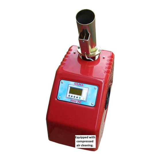
- Page 10 Follow these instructions and pictures to install air cleaning. Set the burner on the edge. Fit the hose supplied. Get the compressor Assemble the compressor wire with the burners. Install the supplied airhose. N.B.! Do not shorten the airhose Start the compressor. It will reduce cleaning.
- Page 11 Programming and information about the PLC control When you for the first time turn on the switch you will see this information on the display. To switch between the menus you use button 1 that points to the left. To program you press in the white button to the very right together with button number 4.
- Page 12 The ignition element of the burner is efficient and ignites the burner within 60-90 seconds. The fast ignition phase and combustion phase do so that the burner fast becomes stable on the flue gas values and also give very low CO- content. In phase two as we call the soft start level, the auger doses, during the up firing phase, the burner 5 times with three seconds operation intervals on the auger...
- Page 13 At this alarm something has happened to the giver that controls the boiler temperature. Do not do any attempts to start the burner, we recommend that you turn off the switch on the burner. Immediately contact your nearest retailer/installer or ULMA AB.
- Page 14 This cause so called vaulting of the fuel. If error under the alarm ”Fuel fault” remains immediately contact your nearest retailer/installer or ULMA AB.
-
Page 15: Electrical Installation
Electrical installation All electrical connections on the burner and auger have high speed contact device see below. 1. Power switch 2. Fuse 3,15Ah 3. Power lead in ( 115 v ) 4. To feed auger ( 115 v ) 5. - Page 16 Follow the instructions for manually cleaning 1. Loosen cables Press catch before pulling out temp sensor connector. 3. Unscrew the cover. 4. Lift off the cover.
- Page 17 6. Lift the rear of the burner. 7. Pill out the inner chamber unit. 8. Clean all combustion holes. 10. N.B ! When the inner chamber unit remounts must be mounted two guide pins placed in holes on the burner. Then remount the reverse order as illustrated on page 16 and 17..
-
Page 18: Wiring Diagram
Wiring diagram... - Page 19 The product is CE-marked which means that it fulfills all prescribed requirements that exist to put the product into work within the EU. ULMA AB disclaims all responsibility that could occur at misuse or wrong use of the Ulma3000TCA burner.
-
Page 20: Warranty Conditions
The installation certificates at the end of this manual shall be filled out with correct information. One to the customer that should be kept in this binder. The other one we would like you to send per mail to ULMA AB. We also prefer that you enclose a print from the flue gas analysis with date and time of the installation. -
Page 21: Test Record
Test record Date: __________________ Model: ____________________ Serial number: ____________________ Control items 1. Connection and tension setting. 2. Programming: Sweden Finland Denmark English Other______________ 3. Functional inspection photo-conductive cell 4. Functional inspection temperature sender 5. Start up of burner: control of ignition unit + screw engine exit 6. - Page 22 Flue gas temp Effect burner (kW) Give fuel deliverer at the service occasion. Bulk, small bags, other etc. If this instruction is not being followed at installation, operation and maintenance ULMA AB is according to existing warranty conditions not bounded.
- Page 23 Flue gas temp Effect burner (kW) Give fuel deliverer at the service occasion. Bulk, small bags, other etc. If this instruction is not being followed at installation, operation and maintenance ULMA AB is according to existing warranty conditions not bounded.
Need help?
Do you have a question about the 3000 TCA and is the answer not in the manual?
Questions and answers