
Subscribe to Our Youtube Channel
Related Manuals for KSB mini-Compacta S-Y/1 Series

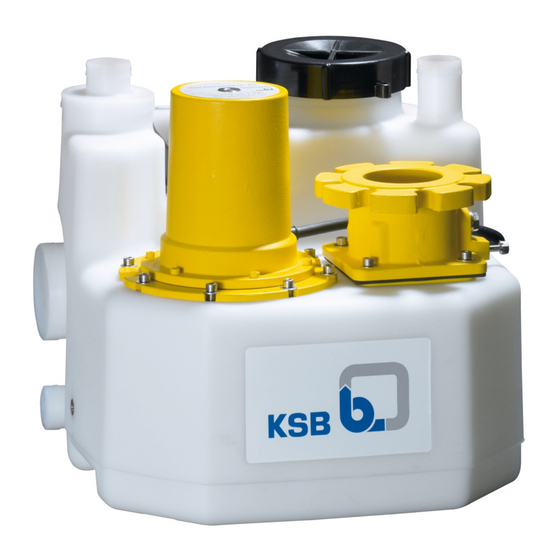
Summary of Contents for KSB mini-Compacta S-Y/1 Series
- Page 1 Floodable Sewage Lifting Unit mini-Compacta From Series S-Y/1 From Series 2013w01 Installation/Operating Manual...
- Page 2 All rights reserved. The contents provided herein must neither be distributed, copied, reproduced, edited or processed for any other purpose, nor otherwise transmitted, published or made available to a third party without the manufacturer's express written consent. Subject to technical modification without prior notice. © KSB SE & Co. KGaA, Frankenthal 27/03/2020...
-
Page 3: Table Of Contents
Contents Contents Glossary .............................. 6 General.............................. 7 Principles ................................ 7 Installation of partly completed machinery.................... 7 Target group.............................. 7 Other applicable documents.......................... 7 Symbols ................................ 7 Key to safety symbols/markings........................ 7 Safety .............................. 9 General................................ 9 Intended use .............................. 9 Personnel qualification and training....................... 9 Consequences and risks caused by non-compliance with this manual ............ 10 Safety awareness ............................ 10 Safety instructions for the operator/user...................... 10 Safety information for maintenance, inspection and installation .............. 10... - Page 4 Contents Prerequisites for commissioning/start-up...................... 33 6.3.1 Lifting unit with LevelControl Basic 1.................... 33 6.3.2 Commissioning with LevelControl Basic 2 .................. 37 Shutdown................................ 39 Operation.............................. 40 Control panel (LevelControl Basic 2) ...................... 40 7.1.1 LED display ............................ 40 7.1.2 Display .............................. 41 7.1.3 Navigation keys.......................... 42 Manual-0-automatic selector switch ...................... 42 Control panel .............................. 42 7.3.1 Displaying measured values ...................... 42 7.3.2...
- Page 5 Contents 10.3.1 mini-Compacta US40 and U60...................... 84 10.3.2 mini-Compacta U100 and US100....................... 85 10.3.3 mini-Compacta UZ150 and UZS150.................... 86 10.3.4 Dimensions of shut-off elements ...................... 87 10.4 Connections .............................. 89 10.4.1 mini-Compacta US40 / U60 ........................ 89 10.4.2 mini-Compacta U100 / US100 ...................... 90 10.4.3 mini-Compacta UZ150 / UZS150 ...................... 91 10.5 Types of connection ............................ 92 10.6 Wiring diagrams ............................. 93 10.6.1 LevelControl Basic 1 - single-phase (1~) ................... 93...
-
Page 6: Glossary
Glossary Glossary ATEX Flood level The acronym ATEX is the French abbreviation for Maximum backflow level of waste water in a "Atmosphère explosible" and refers to the two drainage system European Union (EU) directives covering the area of explosion protection: ATEX Equipment Directive Inlet line 2014/34/EU (also referred to as ATEX 95) and ATEX Pipe used for draining waste water from sanitary... -
Page 7: General
They uniquely identify the pump (set) and serve as identification for all further business processes. In the event of damage, immediately contact your nearest KSB service facility to maintain the right to claim under warranty. 1.2 Installation of partly completed machinery To install partly completed machinery supplied by KSB refer to the sub-sections under Servicing/Maintenance. - Page 8 1 General Symbol Description CAUTION CAUTION This signal word indicates a hazard which, if not avoided, could result in damage to the machine and its functions. Explosion protection This symbol identifies information about avoiding explosions in potentially explosive atmospheres in accordance with EU Directive 2014/34/EU (ATEX).
-
Page 9: Safety
2 Safety 2 Safety All the information contained in this section refers to hazardous situations. DANGER In addition to the present general safety information the action-related safety information given in the other sections must be observed. 2.1 General ▪ This operating manual contains general installation, operating and maintenance instructions that must be observed to ensure safe operation of the system and prevent personal injury and damage to property. -
Page 10: Consequences And Risks Caused By Non-Compliance With This Manual
2 Safety Deficits in knowledge must be rectified by means of training and instruction provided by sufficiently trained specialist personnel. If required, the operator can commission the manufacturer/supplier to train the personnel. Training on the lifting unit must always be supervised by technical specialist personnel. -
Page 11: Unauthorised Modes Of Operation
2 Safety ▪ Decontaminate lifting units which handle fluids posing a health hazard. (ð Section 8.1, Page 48) ▪ As soon as the work has been completed, re-install and re-activate any safety- relevant devices and protective devices. Before returning the product to service, observe all instructions on commissioning. ▪... -
Page 12: Transport/Storage/Disposal
1. On transfer of goods, check each packaging unit for damage. 2. In the event of in-transit damage, assess the exact damage, document it and notify KSB or the supplying dealer and the insurer about the damage in writing immediately. -
Page 13: Storage/Preservation
4. Always complete and enclose a certificate of decontamination when returning the lifting unit. (ð Section 14, Page 102) Always indicate any safety and decontamination measures taken. NOTE If required, a blank certificate of decontamination can be downloaded from the following web site: www.ksb.com/certificate_of_decontamination mini-Compacta 13 of 104... -
Page 14: Disposal
3 Transport/Storage/Disposal 3.5 Disposal WARNING Fluids handled, consumables and supplies which are hot and/or pose a health hazard Hazard to persons and the environment! ▷ Collect and properly dispose of flushing fluid and any fluid residues. ▷ Wear safety clothing and a protective mask if required. ▷... -
Page 15: Description
4 Description 4 Description 4.1 General description ▪ Floodable sewage lifting unit 4.2 Designation Lifting unit Example: mini-Compacta UZ 1.150 D/C Table 6: Designation key Code Description mini-Compacta Type series Design Single-pump lifting unit with free-flow impeller Single-pump lifting unit with cutter Dual-pump lifting unit with free-flow impeller Dual-pump lifting unit with cutter Special design... - Page 16 4 Description Code Description 3-wire connection capacitor motor 40 µF, start capacitor 66 µF Sensors Voltage input 0.5 - 4.5 V Pneumatic level measurement 3.5 m Pneumatic level measurement 10.5 m Bubbler control 2 m Bubbler control 3 m Analog input 4 - 20 mA Float switch Digital level switch ATEX Without ATEX functions With ATEX functions Installation variants Standard...
-
Page 17: Name Plates
4 Description 4.3 Name plates Motor mini-Compacta U1.100 D 2019w04 KSB SE & Co. KGaA Johann-Klein-Straße 9 67227 Frankenthal Deutschland EN 12050-1 400 V 3~ 50 Hz P2 0,75 KW 1,7 A 2800 1/min S3 50% Th.Cl F IP 68 T 40°... -
Page 18: Design Details
4 Description 4.4 Design details Design ▪ Floodable sewage lifting unit to EN 12050-1 ▪ Gas-tight and water-tight plastic collecting tank, pump unit, sensors and control unit ▪ Ready-to-connect sewage lifting unit Drive ▪ Surface-cooled ▪ AC motor / three-phase asynchronous motor ▪... -
Page 19: Configuration And Function
4 Description 4.5 Configuration and function Fig. 4: Illustration of the waste water lifting unit Inlet Hand hole cover Level sensor Vent connection Pump set Discharge-side connection Drain connection Integrated swing check valve Transport lock / float protection 10 Collecting tank fixture Design The waste water lifting unit is designed with a variety of horizontal and vertical inlets (1) and a vertical discharge-side connection (8). - Page 20 4 Description LevelControl Basic 1 ▪ Pump control and monitoring unit in compact plastic housing ▪ For one pump ▪ Level detection via level sensor 0 - 5 V ▪ DOL starting Fig. 5: LevelControl Basic 1 LevelControl Basic 2 Type Basic Compact (BC) ▪...
-
Page 21: Technical Data
4 Description Fig. 7: Type Basic Control Cabinet (BS) 1 Master switch 2 Control panel 3 Manual-0-automatic selector switch 4.6 Technical data 4.6.1 Electrical data (LevelControl Basic 1) NOTE The nominal current must not be exceeded. Table 8: Electrical data of the LevelControl Basic 1 control unit Characteristic Value Nominal operating... -
Page 22: Electrical Data (Levelcontrol Basic 2)
4 Description ▪ Charging time approx. 11 hours when the battery was fully discharged. 4.6.2 Electrical data (LevelControl Basic 2) NOTE The rated current must not be exceeded. Higher currents and power ratings are available on request. Table 9: Electrical data of the LevelControl Basic 2 control unit Characteristic Value Nominal operating... -
Page 23: Fluids Handled
4 Description 4.7 Fluids handled WARNING Pumping of impermissible fluids Hazardous to persons and the environment! ▷ Only discharge permissible fluids into the public sewer system. ▷ Check the suitability of pump/system materials. Variant A (standard design) Permissible According to DIN 1986-3 the following fluids can be discharged into sewer systems: fluids Water contaminated by domestic use, human and - as far as required and permitted - animal faeces together with the necessary flushing water as well as stormwater in... -
Page 24: Scope Of Supply
4 Description 4.10 Scope of supply Depending on the model, the following items are included in the scope of supply: Sewage lifting unit consisting of: ▪ Gas, odour and water-proof collecting tank made of impact-resistant plastic ▪ Fully floodable submersible motor pump(s) ▪... -
Page 25: Installation At Site
5 Installation at Site 5 Installation at Site 5.1 Safety regulations DANGER Improper installation in potentially explosive atmospheres Explosion hazard! Damage to the lifting unit! ▷ Comply with the applicable local explosion protection regulations. ▷ Observe the information in the technical product literature and on the name plates of tank and motor. -
Page 26: Installing The Sewage Lifting Unit
5 Installation at Site Before beginning with the installation check the following: ▪ All structural work required has been checked and prepared in accordance with the dimensions in the outline drawing. 5.3 Installing the sewage lifting unit WARNING Insufficient ventilation Personal injury and damage to property! ▷... -
Page 27: Connecting The Piping
5 Installation at Site NOTE To prevent in-transit damage, the level sensor has been fitted with a transport lock which must be removed prior to commissioning (see Fig.) Fig. 8: Removing the transport lock 5.4 Connecting the piping DANGER Impermissible loads acting on the system nozzles Danger to life from leakage of hot, toxic, corrosive or flammable fluids! ▷... - Page 28 5 Installation at Site Discharge line CAUTION Incorrect installation of discharge line Leaks and flooding of installation room! ▷ Run the discharge line above the flood level before leading it into the sewer. ▷ Do not connect the discharge line to the downpipe. ▷...
-
Page 29: Cellar Drainage
5 Installation at Site Inlet line A gate valve must be fitted so that the inlet line can be shut off temporarily during repair work or servicing. For lifting units directly connected to the toilet, the inlet side gate valve is not required. ü... -
Page 30: Electrical Connection
5 Installation at Site – Head H = H Geodetic Losses Manual drainage For manual drainage of the installation site observe the following: ▪ Minimum pit dimensions 300 × 300 × 500 mm ▪ Hand diaphragm pump available as accessory 5.6 Electrical connection DANGER Electrical connection work by unqualified personnel Risk of fatal injury due to electric shock! -
Page 31: Checking The Direction Of Rotation
5 Installation at Site Connecting the LevelControl Basic 2 control unit ü The mains voltage at the site has been verified against the data on the name plate. 1. Connect the mains cable to the control unit with a suitable cable gland. 2. -
Page 32: Commissioning/Start-Up/Shutdown
6 Commissioning/Start-up/Shutdown 6 Commissioning/Start-up/Shutdown 6.1 Commissioning/Start-up 6.1.1 Prerequisites for commissioning/start-up Before commissioning/start-up of the lifting unit make sure that the following requirements are met: ▪ The lifting unit has been properly connected to the electric power supply and is equipped with all protection devices. ▪... -
Page 33: Supply Voltage
6 Commissioning/Start-up/Shutdown 6.2.2 Supply voltage CAUTION Wrong supply voltage Damage to the lifting unit! ▷ The maximum permissible deviation in supply voltage is 10 % of the rated voltage indicated on the name plate. 6.3 Prerequisites for commissioning/start-up NOTE The control unit parameters have been set at the factory. The parameters need not be changed for commissioning. - Page 34 6 Commissioning/Start-up/Shutdown Setting the unit to the lowest inlet nozzle used The frequency of starts can be reduced by setting the unit to the lowest inlet nozzle used. A switch for this setting is provided on the printed circuit board, which can be accessed after the control unit cover has been opened.
- Page 35 6 Commissioning/Start-up/Shutdown Checking the direction of rotation Always perform the two steps in the sequence given below! ▪ Rotary field of mains connection: The "rotary field" lamp must light up green. If this is not the case, correct the rotary field by interchanging two phases at the mains connection. Fig. 13: Rotary field of mains connection ▪...
- Page 36 6 Commissioning/Start-up/Shutdown Fig. 17: Connecting a fault signalling contact 6.3.1.1.3 Acknowledging alerts NOTE Displayed alerts can be acknowledged by pressing this key. The integrated alarm buzzer will be muted. The alert message disappears as soon as the cause of the alert has gone. Alarms can be acknowledged by pressing the OK key on the front of the control unit.
-
Page 37: Commissioning With Levelcontrol Basic 2
6 Commissioning/Start-up/Shutdown Pump LED "High water" LED Pump Integrated alarm buzzer LiveZero gone Contact 11-14 Depending on closed filling level Power failure: Power failure Contact 11-12 Interval tone closed NOTE If battery voltage drops below 5.3 V (Basic 1) or 10.6 V (Basic 2), the control units automatically switch off the mains-independent alert to prevent excessive discharging of the battery. - Page 38 6 Commissioning/Start-up/Shutdown Fig. 19: Connecting the rechargeable battery (LevelControl Basic 2 BS) 1. Properly connect the rechargeable battery in the control unit. Checking the direction of rotation WARNING Hands or objects inside the tank Risk of personal injury! Damage to the lifting unit! ▷...
-
Page 39: Shutdown
6 Commissioning/Start-up/Shutdown 6.3.2.1 Using additional functions 6.3.2.1.1 Functional check run For pumps with long idle periods, a functional check run can be activated at parameter 3-7-1. The functional check run is carried out weekly for a duration of three seconds. 6.3.2.1.2 External alarm input A NO contact can be connected to LevelControl Basic 2 as external alarm. -
Page 40: Operation
7 Operation 7 Operation DANGER Unintentional starting of pumps Risk of injury: Limbs can be pulled into or crushed by machinery! ▷ Make sure that nobody is within the immediate, hazardous vicinity of the pumps. ▷ Make sure that all piping is properly installed and that the fluid handled cannot escape. - Page 41 7 Operation Table 16: LED description Description Green Trouble-free operation Yellow One or more warnings are active. One or more alerts are active. LED for pump set information These LEDs provide information about the operating status of each pump set. Table 17: LED per pump set Description Green Pump set is ready for operation.
-
Page 42: Manual-0-Automatic Selector Switch
7 Operation 7.1.3 Navigation keys Table 19: Control panel: Navigation keys Description Arrow keys: ▪ Move up/down in the menu options. ▪ Increase/decrease a numerical value. Escape key: ▪ Cancel an entry without saving it. ▪ When entering numbers: Go to the previous digit. ▪... -
Page 43: Displaying And Changing Parameters
7 Operation Table 22: Measured value parameters Parameter Description 1.1.1 Level (Analog) Displays the fill level (analog measurement) [mm] 1.1.3 Mains Voltage Displays the mains voltage [V] 1.2.1 Operating Hours Pump 1 Displays the operating hours of pump set 1 [h] 1.2.2 Start Count Pump 1 Displays the number of starts of pump set 1 1.3.1... - Page 44 7 Operation Step 5 b: Cancelling a parameter value ü The changed parameter value has not been confirmed. 1. To cancel the changed value press the ESC key. ð The parameter value remains unchanged. ð The display shows the selected parameter. Step 6: Leaving the setting mode 1.
-
Page 45: Displaying And Acknowledging Alerts And Warnings
7 Operation Table 24: Parameter list Parameter Description 3.1.2.1 Tank Setting the tank type (may be disabled) 3.1.2.2 Inlet Level Setting the inlet nozzle level to be used for the collecting tank 3.3.4.1 Pumps OFF Level Pumps OFF [mm] 3.3.4.2 Base Load ON Setting the switching point for base load [mm] 3.3.4.3 Peak Load ON... -
Page 46: Displaying The Alerts List
Service interval system ✘ Auto No action (deactivated by default; can be set via the KSB ServiceTool). 7.3.4 Displaying the alerts list The alerts list serves to call up alerts / warnings that have been acknowledged but are still present. Table 27: Displaying the alerts list Step 1: Activating the alerts list ü... -
Page 47: Replacing The Rechargeable Battery
NOTE The rechargeable batteries must be replaced every five years to ensure that the device operates reliably in battery mode. Use original KSB spare parts only. 1. Switch off the power supply. 2. Open the control unit. 3. Disconnect the battery. -
Page 48: Servicing/Maintenance
▪ For any work on the pump (set) observe the operating manual of the pump (set). ▪ Never use force when dismantling and reassembling the equipment. ▪ After maintenance/repair work make sure that inspection cover 160 is closed tightly. ▪ In the event of damage you can always contact KSB Service. mini-Compacta 48 of 104... -
Page 49: Maintenance Schedule
The insulation resistance must be ≥ 2 MΩ. ð Measuring voltage at 3~ 400 V AC: 1000 V DC ð Measuring voltage at 1~ 230 V AC: 500 V DC ð If the values are too low, have the motor overhauled by KSB Service. 8.2.3 Unblocking the cutter mini-Compacta US, UZS If the water level in the tank rises and the alert is triggered without the pump starting up, the cutter may be blocked. - Page 50 8 Servicing/Maintenance 903.02 411.03 Fig. 23: Draining the oil reservoir 3. Place a suitable vessel under screw plug 903.2. 4. Remove screw plug 903.2 with joint ring 411.03. Drain the oil into the vessel. 5. Check the oil and take appropriate action as described in the table. 6.
-
Page 51: Emergency Operation With One Pump
8 Servicing/Maintenance 8.2.4.1 Oil quality Recommended oil quality: ▪ Paraffin oil, thin-bodied, made by Merck, No. 7174, or equivalent ▪ Medical quality ▪ Non-toxic ▪ Recognised as safe and therefore food-approved 8.2.5 Emergency operation with one pump mini-Compacta UZ150, UZS150 NOTE If emergency operation must be ensured during maintenance, inspection or repair work, proceed as follows: 1. -
Page 52: Dismantling The Motor Section
8 Servicing/Maintenance Fig. 25: Loosening the impeller Fig. 26: Lifting off the impeller 8.3.2 Dismantling the motor section mini-Compacta U60, U100, UZ150 1. Remove hexagon socket head cap screws 914.01. 2. Remove screw plug 903.01 with joint ring 411.01. 3. Extract rotor 818 with casing cover 161 from motor unit 80-1. NOTE Place a suitable object (e.g. -
Page 53: Removing The Rotating Assembly
8 Servicing/Maintenance 3. Lift rotating assembly 01-44 out of the tank. 4. Remove O-ring 412.02. mini-Compacta US100, UZS150 1. Separate pump/plate assembly 10-5 from the discharge line. 2. Undo hexagon socket head cap screws 914.06. 3. Lift pump/plate assembly 10-5 out of the tank. 8.3.4 Removing the rotating assembly mini-Compacta US40 1. -
Page 54: Reassembly
8 Servicing/Maintenance NOTE Place a suitable object (e.g. a cylinder, diam. 15 x 15 mm) against the face of shaft 210 and use the screw plug to press the shaft out of motor housing 811. 5. Take O-ring 412.02 out of bearing bracket 330. 6. - Page 55 8 Servicing/Maintenance 421.01 99-15 421.02 920.02 Fig. 27: Fitting the shaft seal 2. Fill the grease reservoir with multi-purpose grease 99-15 (DIN 51 825). 3. Secure the hexagon impeller nut 920.02 with a suitable metal adhesive (e.g. ® Loctite mini-Compacta US40 1. Press lip seals 421.01 and 421.02 into bearing end shield 360, making sure the sealing lips point towards the impeller.
-
Page 56: Fitting The Bearing Assembly/Shaft Seal
8 Servicing/Maintenance 8.4.3 Fitting the bearing assembly/shaft seal mini-Compacta US40 NOTE We recommend fitting new bearings/shaft seals whenever the motor section has been dismantled. At the impeller end, use a pressurisable shaft seal ring. 1. Press lip seals 421.01 and 421.02 into bearing end shield 360, making sure the sealing lips point towards the impeller. - Page 57 8 Servicing/Maintenance NOTE Measure dimension "B" (see Fig. "Checking the impeller clearance"). The impeller clearance "C" results from the difference "A" (= 30 mm) - "B". An impeller clearance of 0.25 to 0.40 mm is required. If necessary, adjust the clearance by adding adjusting washers 551 (set of adjusting washers) between impeller 230 and the shoulder of shaft 210.
-
Page 58: Installing The Float Switch
8 Servicing/Maintenance Fig. 31: Checking the impeller clearance 2. Mount the rotating assembly on plate 185 using hexagon socket head cap screws 914.04 and discs 550.04. 3. Tighten pump casing 100 with studs 902.03, discs 550.03 and nuts 920.03 at lantern 343 to max. 12 Nm. ®... -
Page 59: Tightening Torques
8 Servicing/Maintenance 8.7 Tightening torques mini-Compacta US40 903.01 2 Nm 914.01 6 Nm 914.02 6 Nm 914.03 6 Nm 914.04 914.05 6 Nm 6 Nm Fig. 32: Tightening torques mini-Compacta US40 Table 30: Tightening torques mini-Compacta US40 Connection Tightening torque [Nm] Float switch 81-45 / collecting tank Bearing end shield 360 or pump assembly / collecting tank Motor unit 80-1 / bearing end shield 360... -
Page 60: Disposal/Recycling Of The Lifting Unit
8 Servicing/Maintenance 2x 920.03 2x 550.03 2x 902.03 ↻ 12 Nm 920.03 550.03 Ⓐ 902.03 Fig. 33: Tightening torquesmini-Compacta US100, UZS150 Table 31: Tightening torques mini-Compacta US100, UZS150 Connection Tightening torque [Nm] Rotating assembly 01-44 / collecting tank Plate 185 / collecting tank (US/UZS) Level sensor 81-45 / collecting tank Check valve 747 / collecting tank Motor housing 811 / casing cover... - Page 61 8 Servicing/Maintenance Actions Required during Check expansion joints (if any) for wear. ➀ ➁ Check the shut-off, drain/vent and check valves for proper functioning and tightness. ➀ ➁ Check the collecting tank. ➀ ➁ Clean tank from deposits, if any. In case of major grease deposits in the tank as a result of greasy waste water from industrial businesses, inform the customer that according to DIN 1986-100 a grease separator must be installed (upstream of the lifting unit).
-
Page 62: Trouble-Shooting
Non-compliance will lead to forfeiture of warranty cover and of any and all rights to claims for damages. If problems occur that are not described in the following table, consultation with KSB Service is required. - Page 63 A B C D E F Possible cause Remedy ✘ ✘ Motor winding or power cable are defective. Replace by new original KSB parts or contact the manufacturer. ✘ - Water level in the tank too low during Check level sensor.
-
Page 64: Related Documents
10 Related Documents 10 Related Documents 10.1 General assembly drawings/exploded views with list of components 10.1.1 mini-Compacta U60, U100, UZ150 - Rotating assembly 903.01 411.01 81-59 550.01 321.01 321.01/.02 80-1 412.01 6x 914.01 8x 914.04 8x 550.04 412.11 421.01 99-15 321.02 421.02 550.03... - Page 65 10 Related Documents 80-1 550.01 321.01 903.01 411.01 321.01/.02 81-59 01-44 321.02 6x 914.01 421.01 421.02 8x 914.04 412.01 8x 550.04 412.11 412.12 550.03 550.02 920.02 UG 1088985/Bl.2 Fig. 35: Exploded view of mini-Compacta U60, U100, UZ150 – rotating assembly Part No. Part No.
-
Page 66: Mini-Compacta U60 C, U100 C, Uz150 C - Rotating Assembly
10 Related Documents 10.1.2 mini-Compacta U60 C, U100 C, UZ150 C - Rotating assembly 903.01 411.01 550.01 321.01 80-1 321.01/.02 81-59 932.01 412.01 932.01 321.02 6x 914.01 8x 914.04 8x 550.04 412.11 412.02 421.01 99-15 903.02 411.02 550.08 412.12 932.02 550.03 920.02 550.02... - Page 67 10 Related Documents Part No. Part No. Description Part No. Part No. Description Shaft 550.02 Disc 321.01/.02 Deep groove ball bearing 550.03/.08 Support disc Rotor core pack 550.04 Disc 932.01 Circlip 903.01/.02 Screw plug 99-15 Lubricating oil 914.01 Hexagon socket head cap screw 914.04 Hexagon socket head cap...
-
Page 68: Mini-Compacta U60, U100 - Collecting Tank
10 Related Documents 10.1.3 mini-Compacta U60, U100 - Collecting tank 733.03 719.04 719.03 914.31 550.31 81-45 81-45 412.41 901.04 81-99 412.31 550.04 733.03 82-6 733.01 920.04 99-31 719.01 550.04 733.01 733.02 719.02 914.21 550.21 411.21 733.02 903.21 733.05 900.21 719.05 733.05 412.21 901.05... - Page 69 10 Related Documents Part No. Part No. Description Part No. Part No. Description Valve disc 920.04 Hexagon nut 900.21 Screw 99-3.2 Set of pads 903.21 Screw plug Vent 914.21 Hexagon socket head cap screw mini-Compacta 69 of 104...
-
Page 70: Mini-Compacta Uz150 - Collecting Tank
10 Related Documents 10.1.4 mini-Compacta UZ150 - Collecting tank 733.03 719.04 719.03 733.03 901.04 550.04 99-3.1 920.04 550.04 901.04 550.04 71-11 920.04 550.04 914.21 550.21 411.21 903.21 900.21 914.31 550.31 81-45 903.21 81-45 733.01 412.31 82-16 719.01 81-99 412.23 733.01 412.41 733.02 719.02... - Page 71 10 Related Documents Part No. Part No. Description Part No. Part No. Description Stub flange 99-3.1 Set of installation accessories Bracket Gasket 733.01/.02/ Hose clip 550.04 Disc .03/.05 Check valve Spacer disc Body 901.04 Hexagon head bolt Intermediate piece 920.04 Hexagon nut 411.21 Joint ring...
-
Page 72: Mini-Compacta Us40 - Rotating Assembly
10 Related Documents 10.1.5 mini-Compacta US40 – Rotating assembly 903.01 550.06 411.01 81-59 321.01 80-1 321.01/.02 412.01 6x 914.01 6x 550.01 8x 914.02 8x 550.02 411.02 412.02 55-2 321.02 421.01 99-15 3x 914.03 421.02 3x 550.03 3x 914.04 3x 550.04 23-14 914.05 550.05... - Page 73 10 Related Documents 01-44 550.06 321.01 321.01/.02 411.02 321.02 421.01 421.02 8x 914.02 903.01 8x 550.02 411.01 412.02 55-2 81-59 6x 914.01 23-14 6x 550.01 550.05 914.05 3x 914.03 412.01 3x 550.04 3x 550.03 3x 914.04 80-1 Fig. 40: Exploded view of mini-Compacta US40 – rotating assembly Part No.
- Page 74 10 Related Documents Part No. Part No. Description Part No. Part No. Description 411.01 Joint ring 55-2 Support disc 412.01 O-ring 903.01 Screw plug Motor housing 550.03/.04/.05 Disc 81-59 Stator 914.03/.04/.05 Hexagon socket head cap screw Cable 99-20.03 Screws repair kit Cable gland 550.01/.02 Disc...
-
Page 75: Mini-Compacta Us100, Uzs150 - Rotating Assembly
10 Related Documents 10.1.6 mini-Compacta US100, UZS150 - Rotating assembly 903.01 411.01 550.01 321.01 81-59 80-1 321.01/.025 6x 914.01 932.01 412.01 932.01 412.02 321.02 412.04 412.03 8x 914.04 8x 550.04 2x 914.07 2x 550.07 14x 914.06 14x 550.06 421.01 412.05 2x 902.03 2x 920.03 412.06... - Page 76 10 Related Documents 550.01 321.01 321.01/.02 932.01 8x 914.04 80-1 8x 550.04 411.02 903.02 903.01 412.02 411.01 421.01 81-59 6x 914.01 550.02 932.02 932.01 321.02 412.04 412.01 23-14 2x 914.07 14x 914.06 2x 550.07 14x 550.06 412.03 412.06 2x 902.03 412.05 2x 920.03 2x 550.03...
- Page 77 10 Related Documents Part No. Part No. Description Part No. Part No. Description Bearing bracket Mechanical seal Lantern Set of spacer discs 412.01/.02/ O-ring 550.01 Disc .03/.04/ .05/.06 Ring 550.02 Support disc Set of spacer discs 903.02 Screw plug Parallel pin 932.01/.02 Circlip 719.03/.04...
-
Page 78: Mini-Compacta Us40 - Collecting Tank
10 Related Documents 10.1.7 mini-Compacta US40 – Collecting tank 914.31 82-16 550.31 81-45 81-45 81-99 412.31 733.01 719.01 412.41 733.01 733.02 719.02 733.02 733.06 719.06 733.06 733.05 719.05 733.05 2x 550.05 2x 901.05 2x 732 2x 90-3 99-3.2 Fig. 43: Exploded view of mini-Compacta US40 – collecting tank Part No. -
Page 79: Mini-Compacta Us100 - Collecting Tank
10 Related Documents 10.1.8 mini-Compacta US100 - Collecting tank 412.41 82-16 4x 914.31 4x 550.31 81-45 81-45 412.31 733.01 719.01 81-99 733.01 733.02 719.02 733.02 733.05 719.05 733.05 901.05 550.05 90-3 99-3.2 Fig. 44: Exploded view of mini-Compacta US100 – collecting tank Part No. -
Page 80: Mini-Compacta Uzs150 - Collecting Tank
10 Related Documents 10.1.9 mini-Compacta UZS150 - Collecting tank 82-16 4x 914.31 4x 550.31 81-45 81-45 412.31 81-99 733.01 412.41 733.02 719.01 719.02 733.01 733.02 733.05 719.5 733.05 901.05 550.05 90-3 99-3.2 99-3.2 Fig. 45: Exploded view of mini-Compacta UZS150 – collecting tank Part No. -
Page 81: Connection Examples
10 Related Documents 10.2 Connection examples 10.2.1 mini-Compacta US40, U60, U100, US100 NOTE Provide sufficient clearance (at least 600 mm) in all directions for servicing work. DN 50 DN 50 DN 70 DN 50 DN 50 DN 32 DN 100 DN 100 DN 80/ DN 100 DN 100... -
Page 82: Mini-Compacta Uz150, Uzs150
10 Related Documents 10.2.2 mini-Compacta UZ150, UZS150 NOTE Provide sufficient clearance (at least 600 mm) in all directions for servicing work. Fig. 47: Connection example mini-Compacta UZ150, UZS150 1 Flood level mini-Compacta 82 of 104... -
Page 83: Mini-Compacta Us40 - Concealed In A Pre-Wall System
10 Related Documents 10.2.3 mini-Compacta US40 – concealed in a pre-wall system mini-Compacta US40 can also be installed directly in the bathroom, concealed in a suitable pre-wall system. The distance between the actual wall and the pre-wall should measure at least 400 mm. Please note that an opening in the pre-wall is required for inspection work and maintenance work to be carried out. -
Page 84: Dimensions
10 Related Documents 10.3 Dimensions 10.3.1 mini-Compacta US40 and U60 DN 80/100 DN 50 DN 50 DN 100 DN 100 DN 50 DN 40 Fig. 49: mini-Compacta a) US40 and b) U60 dimensions With gate valve: 745 mm mini-Compacta 84 of 104... -
Page 85: Mini-Compacta U100 And Us100
10 Related Documents 10.3.2 mini-Compacta U100 and US100 Fig. 50: mini-Compacta a) U100 and b) US100 dimensions With gate valve: 745 mm mini-Compacta 85 of 104... -
Page 86: Mini-Compacta Uz150 And Uzs150
10 Related Documents 10.3.3 mini-Compacta UZ150 and UZS150 Fig. 51: mini-Compacta a) UZ150 and b) UZS150 dimensions With gate valve: 1005 mm mini-Compacta 86 of 104... -
Page 87: Dimensions Of Shut-Off Elements
10 Related Documents 10.3.4 Dimensions of shut-off elements 10.3.4.1 Inlet line US40, U60, U100, US100 DN 100/DN 150 DN 100/DN 150 DN 100 DN 100 DN 150 DN 150 Fig. 52: Dimensions of the inlet line with grey cast iron and PVC gate valve, mini-Compacta US40, U60, U100, US100 Tank connection 10.3.4.2 Inlet line UZ150, UZS150 DN 100/DN 150... - Page 88 10 Related Documents 10.3.4.3 Discharge line US40, U60, U100, US100 DN 80 DN 100 DN 50 (2“) DN 50 (2“) Ø108 - Ø115 Ø90 DN 32 (1 1/4“) DN 32 (1 1/4“) DN 32 (1 “) Ø108 DN 80 Fig. 54: Dimensions of the discharge line of mini-Compacta a) US40, b) U60, U100 and c) US100 System component 10.3.4.4 Discharge line of UZ150, UZS150 DN 80...
-
Page 89: Connections
10 Related Documents 10.4 Connections 10.4.1 mini-Compacta US40 / U60 Fig. 56: Connections of mini-Compacta a) US40 and b) U60 Table 35: Connections of mini-Compacta US40 and U60 Number Connection for Number Connection for Inlet DN 100 Inlet DN 100 ① ① ②... - Page 90 10 Related Documents 10.4.2 mini-Compacta U100 / US100 Fig. 57: Connections of mini-Compacta a) U100 and b) US100 Table 36: Connections of mini-Compacta U100 and US100 Number Connection for Number Connection for ① Inlet DN 150/100 ① Inlet DN 150/100 ② Inlet DN 150/100 ②...
-
Page 91: Mini-Compacta Uz150 / Uzs150
10 Related Documents 10.4.3 mini-Compacta UZ150 / UZS150 Fig. 58: Connections of mini-Compacta a) UZ150 b) UZS150 Table 37: Connections of mini-Compacta UZ150 and UZS150 Number Connection for Number Connection for ① Inlet DN 150/100 ① Inlet DN 100/50 Inlet DN 100/50 Inlet DN 150/100 ②... -
Page 92: Types Of Connection
10 Related Documents 10.5 Types of connection mini-Compacta US40, U60, U100, US100 mini-Compacta US40, U60 Connection to a floor-mounted toilet bowl Connection to wall-mounted toilet bowl mini-Compacta U100, US100 mini-Compacta US40, U60, U100, US100 Connection to wall-mounted toilet bowl Pit installation mini-Compacta 92 of 104... -
Page 93: Wiring Diagrams
10 Related Documents 10.6 Wiring diagrams 10.6.1 LevelControl Basic 1 - single-phase (1~) NOTE This control unit is also used for mini-Compacta US40. mini-Compacta 93 of 104... -
Page 94: Levelcontrol Basic 1 - Three-Phase (3~)
10 Related Documents 10.6.2 LevelControl Basic 1 - three-phase (3~) mini-Compacta 94 of 104... -
Page 95: Levelcontrol Basic 2 Type Bc - Dual-Pump Unit - Up To 1.5 Kw, 1
10 Related Documents 10.6.3 LevelControl Basic 2 Type BC - dual-pump unit - up to 1.5 kW, 1~ mini-Compacta 95 of 104... -
Page 96: Levelcontrol Basic 2 Type Bc - Single-Pump Unit With Cutter - Up To 1.5 Kw, Single-Phase 1
10 Related Documents 10.6.4 LevelControl Basic 2 Type BC - single-pump unit with cutter - up to 1.5 kW, single-phase 1~ NOTE Do not use this control unit for mini-Compacta US40. mini-Compacta 96 of 104... -
Page 97: Levelcontrol Basic 2 Type Bs - Dual-Pump Unit With Cutter - Up To 1.5 Kw, 1
10 Related Documents 10.6.5 LevelControl Basic 2 Type BS - dual-pump unit with cutter - up to 1.5 kW, 1~ mini-Compacta 97 of 104... -
Page 98: Levelcontrol Basic 2 Type Bc - Dual-Pump Unit - Dol - Up To 4 Kw
10 Related Documents 10.6.6 LevelControl Basic 2 Type BC - dual-pump unit - DOL - up to 4 kW mini-Compacta 98 of 104... -
Page 99: Eu Declaration Of Conformity
11 EU Declaration of Conformity 11 EU Declaration of Conformity Manufacturer: KSB SE & Co. KGaA Johann-Klein-Straße 9 67227 Frankenthal (Germany) The manufacturer herewith declares that the product: mini-Compacta Serial number range: 2020w01 to 2022w52 ▪ is in conformity with the provisions of the following directives / regulations as amended from time to time: –... - Page 100 Serial number See name plate Intended use For collecting and automatically lifting waste water with or without faeces above the flood level. Manufacturer KSB SE & Co. KGaA 67225 Frankenthal (Germany) Authorised representative Not applicable System of assessment and System 3...
- Page 101 Serial number See name plate Intended use For collecting and automatically lifting waste water with or without faeces above the flood level. Manufacturer KSB SE & Co. KGaA 67225 Frankenthal (Germany) Authorised representative Not applicable System of assessment and System 3...
-
Page 102: Certificate Of Decontamination
14 Certificate of Decontamination 14 Certificate of Decontamination Type: ..........................Order number/ Order item number ..........................Delivery date: ..........................Applications: ..........................Fluid handled ..........................Please tick where applicable ⃞ ⃞ ⃞ ⃞ ⃞ Corrosive Oxidising Flammable Explosive Hazardous to health ⃞... -
Page 103: Index
Index Index Lubrication Oil quality 51 Alerts list Displaying 46 Maintenance work 49 Manual-0-automatic selector switch 42 Bearings 18 Name plate 17 Cellar drainage 29 Navigation keys 42 Certificate of Decontamination 102 Collecting tank 23 Commissioning 33 Operating limits 9 Commissioning/start-up 32 Other applicable documents 7 Control panel 40 Parameters Design 18 Adjusting 43 Designation 15 Partly completed machinery 7 Dimensions 24 Preservation 13 Display 41... - Page 104 KSB SE & Co. KGaA Johann-Klein-Straße 9 • 67227 Frankenthal (Germany) Tel. +49 6233 86-0 www.ksb.com...
Need help?
Do you have a question about the mini-Compacta S-Y/1 Series and is the answer not in the manual?
Questions and answers