Table of Contents
Advertisement
Quick Links
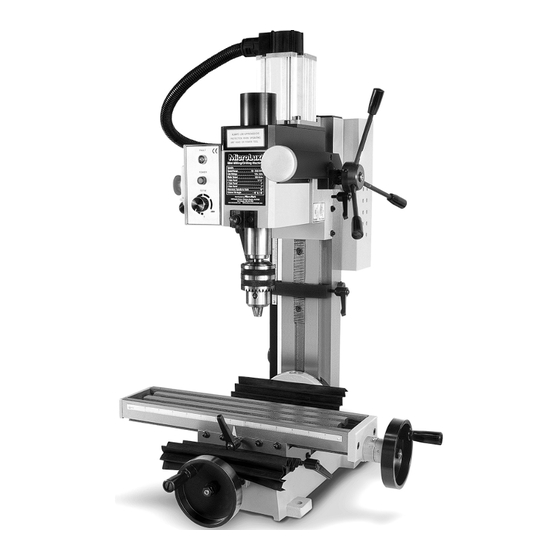
#84630
R8 Mill nstruction Manual
lease read and understand all instructions before using this tool.
Note: These instructions will show you how to assemble this machine,
work its controls and maintain it for long life.
It is not intended as an educational course on how to make parts using a mill.
Made in China for
340 Snyder Avenue
Berkeley Heights, NJ 07922
For technical assistance, call 908-464-1094 Monday thru Friday, 1 pm to 5 pm ET
©Micro-Mark
Advertisement
Table of Contents

Related Manuals for MICRO-MARK MicroLux 84630

Summary of Contents for MICRO-MARK MicroLux 84630
- Page 1 It is not intended as an educational course on how to make parts using a mill. Made in China for 340 Snyder Avenue Berkeley Heights, NJ 07922 For technical assistance, call 908-464-1094 Monday thru Friday, 1 pm to 5 pm ET ©Micro-Mark...
-
Page 2: Table Of Contents
CONTENTS CHAPTER 1 • SPECIFICATION 1-1 Machine specifications 1-2 Packing list of accessories CHAPTER 2 • MACHINE INSTALLATION 2-1 Fundamental locating of the machine 2-2 Preparation before operation 2-3 Starting and running the machine 2-4 Machine overload CHAPTER 3 • MAINTENANCE 3-1 Preventative and maintenance 3-2 Maintenance of cutter and taper shank 3-3 Mechanics lubrication... - Page 3 SAFETY INSTRUCTIONS This machine is electrically powered. For machine longevity: To avoid electric shock: • Make sure all moving parts are lubricated with • Do not use it in or near water. machine oil or grease. • Make sure the drive belt tension is tight enough to •...
-
Page 4: Chapter 1 • Specification
SOME SAFETY FEATURES OF THIS MACHINE a) Purpose of this machine: This machine is designed for drilling, deep milling and face milling of small work pieces up to 300mm x 200mm x 200mm (about 12” x 11” x 11”). b) Before operating this machine: - Read these instructions completely. -
Page 5: Packing List Of Accessories
1.2 Packing list of Accessories 1. Large wrench S:36 2. 1/2” Drill chuck & R8 shank 3. Oil can 4. Fixing pin 5. L hex wrench S:3,4,5,6 6. Spanner wrench D:45-52 7. Double end wrench 8-10,14-17, 17-19 8. Drill chuck holder 9. -
Page 6: Starting And Running The Machine
2.3 Starting and Running the Machine Plug your machine to line power, taking all precautions previously stated and insuring that the speed control knob is full counter-clockwise, setting it to OFF (you will NOT hear an audible click). You may now unlock the Emergency Off Button by pressing in the safety lock on the left side of the switch and then lifting up. - Page 7 3.1-3 Repairs and Maintenance (1) Keep a record of all machine repairs. (2) Do not perform any repairs while the machine is running. (3) Inspect the machine regularly for proper operation; perform all repairs immediately. (4) If you’re unsure about your ability to make repairs, contact your dealer’s service department for assistance.
-
Page 8: Chapter 4 • Machine Structure
CHAPTER 4 • MACHINE STRUCTURE 4.1 External Features A. Motor B. Fine feeding wheel C. Headstock and spindle D. Longitudinal feed hand wheel E. Work table Saddle G. Cross feed hand wheel H. Base Connecting strut Limit block K. Controller L. -
Page 9: Assembly And Parts
4.3 Assembly and Parts... - Page 11 PARTS LIST Item No. Part Name Qty. Item No. Part Name Qty. Item No. Part Name Qty. Screw M8 x 55 Fixed sleeve Connect board for motor Handle Screw M3 x 8 Cover Nut M8 Bracket Spindle box Washer 8 Ruler Screw M6 x 25 Handle...
-
Page 12: Chapter 5 • Mechanism Adjustment
CHAPTER 5 • MECHANISM ADJUSTMENT 5.1 Installation and Removal of Taper Shank Installation (1) Turn off the main power before you replace the cutter. (2) Remove the protective cover (a). (3) Wipe the spindle sleeve and R8 shank. (4) Put the shank (g) into spindle sleeve with chuck. Cutter should be held with a cloth to protect machine and fingers. -
Page 13: Adjust Tip Angle Of Headstock
5.3 Adjust Tip Angle of Headstock (1) Turn off main power before adjusting (2) Hold the headstock firmly to avoid damaging the machine or injury to the operator. (3) Loosen the lock nut (a) with large wrench (b). (4) djust the headstock to the desired tip angle (45˚... - Page 14 Face Milling 1. Follow instructions in section 5 to install cutters. Be sure cutters are held tightly. 2. Select appropriate speed level. 3. Use vise or hold down clamps to attach workpiece to the milling table. 4. djust worktable (Longitudinal xis Y) and Saddle seat (Cross xis X) in position. 5.
-
Page 15: Power Connection/Disconnection & Operation
CHAPTER 7 • POWER CONNECTIONS & ELECTRICITY 7.1 Power Connection/Disconnection & Operation (1) The connection, disconnection and grounding is carried out through the plug, equipped on the machine. For safety reasons, do not change this plug into any other type under any circumstances. (2) For the protection of control device, we recommend the operator to supply a fuse with a current rating and the total length between fuse and connection terminal according to the following Extension Lead Chart.
Need help?
Do you have a question about the MicroLux 84630 and is the answer not in the manual?
Questions and answers