
Related Manuals for PROMETHEUS PATHWAY MR-20

Summary of Contents for PROMETHEUS PATHWAY MR-20
- Page 1 PATHWAY® MR-20 Dual Channel EMG System with Alpha/Numeric LCD Display (Part #9710)
- Page 2 Made in the U.S.A. PATHWAY MR-20 OPERATOR’S GUIDE ®...
- Page 3 One Washington Street, Suite 3171 Dover, New Hampshire 03820 U.S.A. Tel: 1.800.442.2325 Fax: 603.749.0511 theprogrp.com | info@theprogrp.com PATHWAY MR-20 OPERATOR’S GUIDE ®...
- Page 4 United States patents and other pending United States and foreign patents. The Prometheus Group logo and combinations thereof, ® Pathway and Telesis are registered trademarks of The Prometheus Group ® ® ® Inc., One Washington Street, Suite 3171, Dover, NH 03820. Easytrode is a ™...
- Page 5 Est. 1989 Technical Support: Dear Valued Customer, Tech Support Phone: On behalf of The Prometheus Group®, we would like to personally thank 1-800-272-8492 you for your recent purchase. Tech Support Email: Support@theprogrp.com The Prometheus Group® is recognized for providing exceptional...
-
Page 6: Table Of Contents
TABLE OF CONTENTS NOMENCLATURE..................7 SERVICE INFORMATION................7 INDICATIONS FOR USE................8 CONTRAINDICATIONS..................8 APPLICATIONS....................8 Cautions.......................8 Warnings and Prohibitions................9 Contents of Kit....................12 CHAPTER 1: PHYSICAL/MECHANICAL OVERVIEW........13 Front and Bottom Panels................13 Top Panel....................14 Rear Panel....................15 Installing & Replacing the Battery...............16 CONNECTING THE PATHWAY PREAMPLIFIER CABLES ®... - Page 7 Max Display....................32 Ratio Display Mode..................34 Special Functions Chart................35 Obsolete Functions..................35 Selecting WORK/REST MODE..............36 Display Data....................38 Clear Data....................40 Response Time..................41 Lock Mode....................42 Software Available..................43 Telesis Software for the Pathway MR Series (Sold Separately).....43 ® ® CONNECTING THE PATHWAY MR-20 TO A COMPUTER....45 ®...
-
Page 8: Nomenclature
Please call 1-800-272-8492 in the U.S.A. and Canada, or +1 (011) 603-742-6053 international, or e-mail support@theprogrp.com. The device should be serviced by The Prometheus Group ® qualified Technical Support personnel when: • Any cable, cord, or plug has been damaged. -
Page 9: Indications For Use
INDICATIONS FOR USE Surface electromyography is a safe and effective technique for relaxation training and muscle re-education. When using internal sensors such as the Pathway Vaginal EMG Sensor: ® EMG biofeedback is a safe and effective technique for the assessment and treatment of pelvic floor dysfunction and monitoring the performance of Kegel exercises. -
Page 10: Warnings And Prohibitions
Be sure to read this operator’s manual before using this device. Use by improperly trained personnel or non-licensed healthcare professionals may cause damage to the equipment or harm to the patient. Use only electrodes and accessories from The Prometheus Group ® with the Pathway MR-20 device. Any other electrodes or ®... - Page 11 DO NOT leave electrodes attached when device is not in use. To reduce the risk of electrical shock, DO NOT open the device housing. Refer all servicing to The Prometheus Group ® qualified Technical Support personnel. DO NOT prematurely unpack electrodes as prolonged exposure to air may cause the electrode adhesive to dry out.
- Page 12 WARNINGS & PROHIBITIONS (CONTINUED) Use only heavy-duty 9V alkaline batteries with this device, DO NOT use any type of line-powered adapter. For the treatment of relaxation training and muscle re-education. DO NOT attempt to use this device simultaneously with stimulation being supplied from an electrical muscle stimulator.
-
Page 13: Contents Of Kit
CONTENTS OF KIT Before using the Pathway MR-20 for the first time, carefully open the box and ® confirm that all equipment and accessories listed below are included and agree with the packing list or invoice. If there are questions about the contents, or you wish to order additional supplies, please call Customer Service, Toll-Free: 1-800-442-2325 in... -
Page 14: Chapter 1: Physical/Mechanical Overview
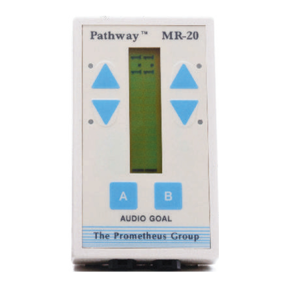
CHAPTER 1: PHYSICAL/MECHANICAL OVERVIEW Front and Bottom Panels Dual Channel LCD Display Four LED Indicator Lights (Bar Graph) Up and Down Arrow Keys for Channel B Channel “B” Key Up and Down Arrow Keys for Channel A EMG B Channel “A” Key EMG A The device pictured above is the Pathway MR-20 Dual Channel EMG System with... -
Page 15: Top Panel
EMG controlled stimulation. A FUNCTIONAL STIMULATOR IS A SEPARATE DEVICE FOR STIMULATION AND IS NOT AVAILABLE FROM THE PROMETHEUS GROUP ® NOTE: The Pathway MR-20 DOES NOT produce electrical stimulation. -
Page 16: Rear Panel
CHAPTER 1: PHYSICAL/MECHANICAL OVERVIEW Rear Panel Durable clip for a secure hold Serial Number Location The serial number of the device is located inside the battery compartment. See above diagram for exact location. The above image is a close up view of the battery compartment with the serial number location highlighted. -
Page 17: Installing & Replacing The Battery
CHAPTER 1: PHYSICAL/MECHANICAL OVERVIEW Installing and Replacing the Battery To install or change the battery, remove cover by pressing down on the designated area of the compartment cover and slide it in the direction indicated. Place the new battery in compartment, noting orientation of battery terminals. Replace the cover, snapping firmly into place. -
Page 18: Pathway ® Electrodes (Part #6750)
CHAPTER 1: PHYSICAL/MECHANICAL OVERVIEW Cable Connections for Orthopedic: Connecting the Pathway ® Preamplifier(s) (Part #2583) to Pathway Electrodes (Part #6750) ® EMG B: To monitor secondary muscle EMG A: To monitor primary muscle Pathway Preamplifier, Available in White Pathway Electrode (Rectangular, 3 Snaps ®... - Page 19 CHAPTER 1: PHYSICAL/MECHANICAL OVERVIEW Cable Connections for Orthopedic: Connecting the Pathway ® Preamplifier(s) (Part #2583) to Pathway Electrodes (Part #6750) ® Connecting Pathway Electrode(s) to Pathway Preamplifier(s): The Pathway ® ® ® Preamplifiers (Part #2583) have three female snap on electrode positions: two labeled (ACT) for active electrodes and one (GND) for the ground electrode.
-
Page 20: Pathway ® Adapter (Part #3660)
CHAPTER 1: PHYSICAL/MECHANICAL OVERVIEW Cable Connections for Internal Pelvic Floor: Connecting the Pathway ® Adapter (Part #3660) to the Pathway Intracavity Sensors (Part #6330, ® Part #6320, and Part #6340) EMG B: Accessory muscle placement: Commonly monitored accessory muscles include abdominals, leg adductors, & gluteals EMG A: To monitor primary muscle Pathway Adapter (Part #3660) -
Page 21: Pathway ® Intracavity Sensors
CHAPTER 1: PHYSICAL/MECHANICAL OVERVIEW Connecting the Pathway Preamplifier to the Pathway Adapter: Open the Velcro ® ® sleeve of the Pathway Adapter (Part #3660), and match the female snaps on the end ® of the Pathway Preamplifier (Part #2583) with the male snaps of the Pathway Adapter ®... - Page 22 CHAPTER 1: PHYSICAL/MECHANICAL OVERVIEW Pathway Intracavity Sensors (Part #6320) ® Pathway Vaginal/Rectal EMG Sensor (Part #6320) Rectal Placement: For proper ® orientation of the sensing surfaces, insert the Pathway Vaginal/Rectal EMG Sensor ® (Part #6320) into the rectum so the sensor base rests up against the anus and the tab is pointed up toward the pubis.
-
Page 23: Pathway ® Rectal Emg/Stimulation Sensor (Part #6340)
• Indications for Use • Contraindications for Use • Warranty Information Additional cleaning instructions can also be found on page 51 at the back of this Operator’s Guide. NOTE: ALL PROMETHEUS GROUP SENSORS ARE RESTRICTED TO ® SINGLE PATIENT USE ONLY. PATHWAY MR-20 OPERATOR’S GUIDE... -
Page 24: 24" Electrode Lead Wire Set (Part #5328)
CHAPTER 1: PHYSICAL/MECHANICAL OVERVIEW Cable Connections for External Pelvic Floor: Connecting the Pathway Adapter (Part #3660) to the 24” Electrode Lead ® Wire Set (Part #5328), and Easytrode Pregelled Electrodes (Part #6801) ™ EMG B: Accessory muscle placement: Commonly monitored accessory muscles include abdominals, leg adductors, &... - Page 25 CHAPTER 1: PHYSICAL/MECHANICAL OVERVIEW External Pelvic Floor Placement of Easytrode Pregelled Electrodes ™ (Part #6801) take the 24” Electrode Lead Wire Set plug end (male six-pin mini din connector), with flat side up, then take the Pathway Adapter (Part #3660), noting the notched top of the ®...
-
Page 26: Disposable Lead Wire Electrodes (Part #7400)
CHAPTER 1: PHYSICAL/MECHANICAL OVERVIEW Cable Connections for External Pelvic Floor: Connecting the Pathway Adapter (Part #3660) to the Adapter for Disposable Lead Wire ® Electrodes (Part #7100) to the Disposable Lead Wire Electrodes (Part #7400) EMG B: Accessory muscle placement: Commonly monitored accessory muscles include abdominals, leg adductors, &... - Page 27 CHAPTER 1: PHYSICAL/MECHANICAL OVERVIEW Surface Perineal Placement of Disposable Lead Wire Electrodes (Part #7400) Connecting Disposable Lead Wire Electrodes to the Adapter for Disposable Lead Wire Electrodes: Insert the Disposable Lead Wire Electrodes (Part #7400) into the Adapter for Disposable Lead Wire Electrodes (Part #7100) ensuring the two red (active) lead wires and the single green (ground) lead wire are inserted completely and match the color on the Adapter for Disposable Lead Wire Electrodes (Part #7100).
-
Page 28: Chapter 2: Operation
CHAPTER 2: OPERATION Display Modes To Start Up the Display • Turn the device ON by rotating the thumbwheel switch clockwise. The thumbwheel switch also adjusts the volume. • The device will display SELF TEST upon power up. • After the SELF TEST has been completed, 4 LEDs will be activated in sequence, the device will sound a tone which can be used to adjust the volume... - Page 29 CHAPTER 2: OPERATION Display Modes After a few seconds, a screen showing the CURRENT SESSION IS # will appear. In this example, the current session is 1. Following this screen, there may be a battery voltage warning screen. BATTERY LOW! REPLACE SOON! This warning indicates you can complete the current session and then replace the battery prior to additional...
-
Page 30: Standard Modes
CHAPTER 2: OPERATION Standard Modes The Channel A key is used to set the feedback mode for EMG A and the Channel B key for EMG B. Since the EMG A is the primary Channel, set up the mode for EMG A first, then EMG B. - Page 31 CHAPTER 2: OPERATION Goals (Continued) Press the A or B key 2x- ABOVE TONE ABOVE TONE: Is used to provide the patient with auditory and visual goals for contracting the muscle. Press the A or B key 3x- BELOW TONE BELOW TONE: Is used to provide the patient with auditory and visual goals for inhibiting or relaxing the muscle.
- Page 32 CHAPTER 2: OPERATION Goals (Continued) Changing the Goal Value From the Default of 10 µV Use the Up and Down Arrow Keys to change the goal value for EMG A and EMG B. Single key presses will incrementally increase or decrease the goal value. Use the Up Arrow Key to increase the goal value, and the Down Arrow Key to decrease the goal value.
-
Page 33: Stim
CHAPTER 2: OPERATION Stim NOTE: The Pathway MR-20 DOES NOT produce electrical stimulation. ® Working with a Functional Stimulator In order to use the Pathway MR-20 to control a functional stimulator, it must be ® configured properly, and the device must be connected via the stim interface cable. - Page 34 CHAPTER 2: OPERATION Max Display (Continued) The MAX DISPLAY MODE can be used for either or both Channels, and either Channel may be set to the MAX DISPLAY MODE while the other Channel is set to any of the other functions. Ratio Display Mode Press the A key 7x- RATIO A/B...
-
Page 35: Ratio Display Mode
CHAPTER 2: OPERATION Ratio Display Mode Channel Channel Ratio of Channel A to Channel B “A” “B” RATIO A/B MODE has a default ratio goal of 1:1 represented by the tip of the arrow. The top of the LCD Bar Graph peaks at 10:1 and the bottom of the LCD Bar Graph is 0.1:1. -
Page 36: Special Functions Chart
THE PATHWAY MR-20 DOES NOT PRODUCE STIMULATION. For details ® on the operation of the STIM FUNCTION, see page 32 for details, or contact The Prometheus Group at 1-800-272-8492. ® NOTE: Special functions time out after 5 seconds. PATHWAY MR-20 OPERATOR’S GUIDE... -
Page 37: Selecting Work/Rest Mode
CHAPTER 2: OPERATION Special Functions NOTE: If a goal is desired, it MUST be set before the Work/Rest Mode. Selecting the WORK/REST Mode Press the Channel “A” and the Channel “B” keys simultaneously for approximately 3 seconds. = Patient Data = Setup SETUP TIMING... - Page 38 CHAPTER 2: OPERATION Selecting the WORK/REST MODE (Continued) Use the Up and Down Arrow Keys to adjust between 0 and 180 seconds. Use the Up and Down Arrow Keys to set the number of trials (combination of work and rest intervals) between 1 to 20 trials.
-
Page 39: Display Data
CHAPTER 2: OPERATION Display Data Press the “A” and the “B” keys at the same time or approximately 3 seconds. PATIENT DATA REVIEW DATA DISPLAY DATA Press the Up or Down Arrow Keys to show the SESSION #. Press the Channel A and Channel B Keys to display individual Channel values. - Page 40 CHAPTER 2: OPERATION Display Data Patient Data Menu The Pathway MR-20 is capable of saving up to 32 training sessions in the ® memory storage area. This memory will be preserved IF THE BATTERY IS DISCONNECTED. In the CONTINUOUS MODE, the Pathway MR-20 will store a training session if the ®...
-
Page 41: Clear Data
CHAPTER 2: OPERATION Clear Data NOTE: Individual sessions cannot be erased. NOTE: If sessions are cleared, they cannot be recovered. Press the “A” and the “B” keys at the same time or approximately 3 seconds. PATIENT DATA REVIEW DATA CLEAR DATA CLEAR ALL This screen will appear taking the position of the... -
Page 42: Response Time
CHAPTER 2: OPERATION Response Time Press the Channel “A” and the Channel “B” keys at the same time or approximately 3 seconds. RESPONSE TIME is an algorithm used by the Pathway MR-20 to calculate the ® response of the EMG signal. Rapid movements may require a faster response time to show change on the LCD Bar Graph. -
Page 43: Lock Mode
CHAPTER 2: OPERATION Lock Mode Press the Channel “A” and the Channel “B” keys at the same time or approximately 3 seconds. Lock the Pathway MR-20 Unlock the Pathway MR-20 ® ® SETUP SETUP SETUP SETUP LOCK MODE LOCK MODE LOCK VALUES UNLOCK Note that the start-up screen now reads MODE: LOCKED and the keys are not active. -
Page 44: Software Available
CHAPTER 2: OPERATION SOFTWARE AVAILABLE Telesis Software for the Pathway MR Series (Sold Separately) ® ® Telesis Software Complements the PATHWAY MR Series by Enhancing ® ® Assessment, Performance, and Providing Documentation Multiple Display Options - Extensive library of treatment displays to include animated video clips, color graphics, and the ability to modify application protocols. - Page 45 CHAPTER 2: OPERATION Minimum Computer Requirements for Telesis Software ® Windows 10 Professional 64 Bit Operating System Intel i5 Processor or Higher CPU RAM: 8 GB RAM 500 GB Minimum Available Hard Drive Space (To allow for database expansion) NOTE: Software must be purchased in order to use the Pathway MR-20 ®...
-
Page 46: Connecting The Pathway ® Mr-20 To A Computer
CHAPTER 2: OPERATION Connecting the Pathway MR-20 to a Computer ® Connect the Pathway MR-20 to the computer using the USB cable provided with ® software purchase. Connect the USB cable into the port on the top of the device labeled “SERIAL”. -
Page 47: Chapter 3: Troubleshooting
CHAPTER 3: TROUBLESHOOTING Erratic Readings “My Pathway MR-20 is giving me unstable readings and I don’t ® know what’s wrong?” 1. Test the Pathway Preamplifier (Part #2583), as it may be worn: ® A. Perform a preamplifier test to verify that both cables are functioning properly. - Page 48 ® (Part #6330, Part #6340, or Part #6320). Reconnect device, accessories and consumables, and if the readings continue to be unstable, then the sensor was causing the issue. For further assistance, please contact The Prometheus Group ® at 1-800-272-8495. PATHWAY MR-20 OPERATOR’S GUIDE...
-
Page 49: High Baseline Readings
CHAPTER 3: TROUBLESHOOTING High Baseline Readings “My patient is getting higher than normal readings at rest.” 1. If utilizing a powered exam table, disconnect power once patient is situated. Check rest readings. 2. If using a laptop with a good battery, disconnect the laptop power supply from both the wall and the computer. -
Page 50: Battery Check
CHAPTER 3: TROUBLESHOOTING Battery Check “My Pathway MR-20 won’t turn on or keeps shutting off.” ® 1. Disconnect the Pathway Preamplifier(s) (Part #2583) and power the device off and ® then on again. If the device powers on, then it may be the Pathway Preamplifier ®... -
Page 51: Pathway ® Mr-20 Care And Maintenance
CHAPTER 3: TROUBLESHOOTING PATHWAY MR-20 CARE AND MAINTENANCE ® STORAGE Store your Pathway EMG device in the carry pouch provided to keep the device ® safe, dry, and clean. Detach and discard electrodes from the Pathway Preamplifier (Part #2583) when ®... -
Page 52: Cleaning
(no stronger than a 1:10 ratio mixture), or 2% glutaraldehyde solution (such as Cidex) is recommended. After disinfection, wipe the cable and lead wires with water using a clean damp cloth and then a clean dry cloth. Prometheus Group cables and lead wires are reusable and are provided non-sterile. ®... -
Page 53: Chapter 4: Pathway ® Mr-20 Technical Specifications
CHAPTER 4: PATHWAY MR-20 TECHNICAL SPECIFICATIONS ® SPECIFICATIONS • Active Electrode Preamplifier • Two Channel EMG • 1 - 800 Microvolt Range • One Logarithmic Display Range • Above/Below Goals • True RMS Conversion • Reading Rate: Every 100 Milliseconds •... -
Page 54: To Order Accessories
TO ORDER ACCESSORIES To re-order accessories and consumables for any Pathway device, please call your ® local distributor or The Prometheus Group sales office at 1 (800) 442-2325 in the U.S. ® and Canada, or +1 (011) 603-749-0733 for international. -
Page 55: Quick Reference Guide
CHAPTER 4: PATHWAY MR-20 TECHNICAL SPECIFICATIONS ® PATHWAY MR 20 QUICK REFERENCE GUIDE ® To set an A Channel GOAL, press the A key 2x or 3x. To change GOAL A, press the UP AND DOWN ARROWS. To set a B Channel GOAL, press the B key 2x or 3x. To change GOAL B, press the UP AND DOWN ARROWS. -
Page 56: Standard Warranty Service Agreement
This warranty shall include all parts and ® labor charges. The purchaser must obtain a Return Authorization Number and must return the defective unit, at the purchaser’s own expense to The Prometheus Group . The Prometheus Group may, at its option, repair and return the unit or ®... - Page 57 This warranty specifically limits the liability of The Prometheus Group , including liability for negligence claims by users and ® disclaiming any other claims of non-performance by The Prometheus Group ® In no event shall The Prometheus Group be held liable for any incidental or ®...
- Page 58 One Washington Street, Suite 3171 Dover, New Hampshire 03820 U.S.A. Tel: 1.800.442.2325 Fax: 603.749.0511 theprogrp.com | info@theprogrp.com PATHWAY MR-20 OPERATOR’S GUIDE ®...
- Page 59 52_075bEN PATHWAY MR-20 OPERATOR’S GUIDE ®...
Need help?
Do you have a question about the PATHWAY MR-20 and is the answer not in the manual?
Questions and answers