
Subscribe to Our Youtube Channel
Related Manuals for JRC JHS-7


Summary of Contents for JRC JHS-7
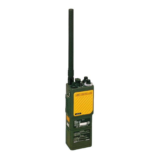
- Page 1 JHS - 7 150MHz/1W, TWO-WAY RADIOTELEPHONE APPARATUS/ 150MHz/1W, TWO-WAY RADIOTELEPHONE APPARATUS/ ON-BOARD COMMUNICATION EQUIPMENT ON-BOARD COMMUNICATION EQUIPMENT INSTRUCTION INSTRUCTION MANUAL MANUAL...
- Page 3 Turn off the power switch of the transceiver after using. Overdischarge of the battery (6V or lower) will cause serious deterioration of the battery performance. Return unusable secondary batteries to a nearest JRC branch, sales office or dealer. Charge the secondary battery (NBB-248/248A) before using the transceiver at the first time to revive the reduced capacity during transportation.
- Page 4 ・DO NOT disassemble or DO NOT modify. When exchanging the primary battery, ・DO NOT puncture or DO NOT deform Contact to nearest JRC branch office or JRC agent. Mishandling can cause explosion, over- heating or leakage of strong alkaline Specifications electrolyte solution.
- Page 5 Handling of the carrying strap The JHS-7 radiotelephone is provided with the shoulder and/or neck carrying strap. For fixing the strap to the radiotelephone, two fittings on the upper part as shown below are available. Additionally the strap includes the weak links to prevent the bearer from being ensnared.
- Page 6 Avoid charging it especially at an ambient temperature below 0℃ . 4. When the secondary battery is out of use, bring it to a nearby JRC sales office, branch, or dealer. 5. The antenna is firmly assembled with the radiotelephone. Any attempt to forcibly remove the antenna will cause damage to the antenna or the equipment.
-
Page 7: Table Of Contents
TABLE OF CONTENTS GENERAL ····································· 1 TROUBLESHOOTING ···················· 11 General ································ 1 Precautions ·························· 11 Features ······························· 1 Troubleshooting Guide ············ 11 Composition ·························· 1 Simple Adjustment ··············· 12 1.3.1 Standard Components ··········· 1 6.3.1 Checking of Voltages ··········· 12 1.3.2 Option ·······························... -
Page 8: General
Regulation. signals are being transmitted. Charge lamp Note: The JHS-7 for JG Flag is equipped with no When the battery energy is almost consumed, the optional channel. BUSY lamp blinks for indicating necessity of the battery charging. -
Page 9: Specifications
CH17 (156.850MHz) (20) Weight: Approx. 600g CH67 (156.375MHz) 2.2 Transmitter Note: Usable channels of the JHS-7 for JG flag (1) Carrier output power: 0.8W are restricted to CH15, CH16, and CH17. (2) Effective radiated power: More than 0.25W (2) Optional channels:... -
Page 10: Operation
3. OPERATION 3.1 Description (1) Helical antenna The flexible helical antenna is firmly assembled with this radiotelephone. To remove the antenna, exclusive wrench is required. (2) Shoulder belt fittings Fasten the attached shoulder belt to these fittings before using the belt to carry the radiotelephone. -
Page 11: Operating Procedure
(10) Tx lamp 3.2 Operating Procedure Lights red during press-to-talk operation. 3.2.1 Preparation It monitors the transmission output. If the Tx Set a desired channel number. lamp does not light even when the PTT button Turn the squelch control fully is depressed, the transmission circuit may be counterclockwise. -
Page 12: Closing Down
As soon as you get an answer from the 3.3 Replacement of Battery Pack NBB-248/248A /389 partner station, inform it of the receiving (1) Removal conditions using numbers shown in Table While holding down the PUSH button on the 3-1 below. left side of the radiotelephone, twist Battery Example: “The sensitivity and clarity of Pack counterclockwise. -
Page 13: Handling Of Battery Charger Nba-4141/Nba4141A(Optional)
3.4 Handling of Battery Charger NBA-4141/NBA-4141A (Optional) 3.4.1 Installation The battery charger can be installed on a desk top or on a wall. Figures 3-4, 3-5, and 3-6 illustrate how to install it. When it is installed on a wall, the fixing angle A may be 0°, 30°, or 45°. -
Page 14: Replacement Of Fuse
3.4.2 Replacement of Fuse Terminal of the Remove the plug of the AC power cable for Power Supply Voltage power transformer. the battery charger from the convenience AC100V ~ 110V 105 V outlet. AC115V ~ 120V 115 V Remove the power supply terminal AC200V ~... -
Page 15: Handling Of The Accessories
3.5 Handling of the Accessories 3.5.3 Connecting of the Earphone and External 3.5.1 Carrying Strap Speaker/Microphone The attached carrying strap facilitates carrying the radiotelephone on shoulder. To fasten the Connect the optional earphone 6UMJD00004 and strap, use the two fittings on the upper part of external speaker-microphone 6UMJD00029 the radiotelephone as shown in Figures 3-12 and to the RMT (remote terminal) connector on the... -
Page 16: Battery Charging
(1) Attach the AC plug of the battery charger NBA-4141/NBA-4141A to the convenience outlet. (2) Turn off the JHS-7, and insert the battery pack into the battery charger, as shown in Figure 4-1, with or without the radiotelephone Figure 4-1 Inserting of Battery Pack mounted on the pack. -
Page 17: Maintenance And Inspection
5. MAINTENANCE AND INSPECTION 5.1 Daily Maintenance The life of an equipment like the radiotelephone largely depends on the quality of maintenance. It is very important to check the radiotelephone regularly to keep it in its best condition. Regular inspection helps to find a symptom of trouble or prevent trouble before it occurs. -
Page 18: Troubleshooting
If the removal is forced by any other means, the antenna or the radiotelephone will be damaged. Ask a nearest JRC dealer or branch if the removal is necessary. (2) Before making repairs or asking for repairs, check fundamental matters such as operating procedures and battery conditions. -
Page 19: Simple Adjustment
6.3 Simple Adjustment This subparagraph describes simple adjustment 6.3.4 Transmit Output Adjustment Remove the antenna using the exclusive procedure that can be followed without use of wrench. special measuring instruments. Connect a power meter (50Ω) to the Before simple adjustment, perform the following antenna terminal. -
Page 20: Options
7. OPTIONS 7.6 External Speaker/Microphone 6UMJD00029 The following options are available to make the best The external speaker/microphone is helpful when use of the JHS-7. the radiotelephone is carried around one’s waist. Microphone sensitivity: -66dB±4dB at 7.1 Battery Charger NBA-4141/NBA-4141A 1kHz(0dB=1V/μbar) - Page 28 Not use the asbestos For further information,contact: URL Head office : http://www.jrc.co.jp/eng/ Marine Service Department 1-7-32 Tatsumi, Koto-ku, Tokyo 135-0053, Japan : tmsc@jrc.co.jp e - mail : +81-50-3786-9201 One - call ISO 9001, ISO 14001 Certified CODE No.7ZPJD0669A SEP. 2018 Edition 1...
Need help?
Do you have a question about the JHS-7 and is the answer not in the manual?
Questions and answers
I WOULD LIKE TO KNOW JRC JHS 7 PRIMARY BATTERY NBB 248A VALIDATION AND EXPIRATION ?
The NBB-248A is a secondary (rechargeable) battery, not a primary battery. It must be charged before first use to restore capacity reduced during transport. Overdischarge (below 6V) and prolonged trickle charging can deteriorate its performance. Expiry date and shelf life details apply to the NBB-389 lithium primary battery, which has a five-year shelf life.
This answer is automatically generated