Advertisement
RKAmp2 2.5+2.5W Audio Amplifier Component List and Instructions
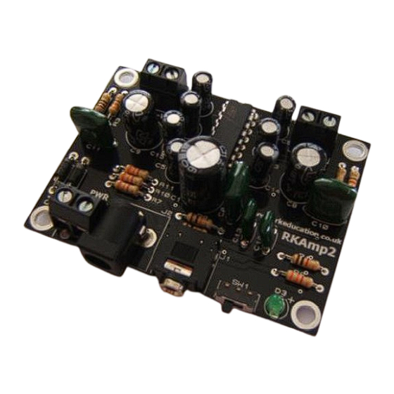
The RKAmp2 stereo amplifier PCB has been designed around the TEA2025B 2 x 2.5 Watt stereo
amplifier I.C.
The sound signal is inputted into the circuit via a 3.5mm stereo socket
The amplifier has 2 channels of up to 2.5 Watts per channel
Produces a very high quality sound output
The PCB includes a power switch
The PCB includes a power LED
The PCB uses terminal blocks
Battery powered between 4.5V and 12V
Power is inputted to the PCB via a terminal block or jack socket
Compact design
Low cost
The PCB is a high quality double sided black PCB
A large ground plane is used to aid with dissipating heat
Component List
C1 – 1000uF 16VDC electrolytic radial capacitor
C2 – 100nF capacitor (tall green capacitor marked 104, non-polarised)
C3 ~ C7 – 100uF 16VDC electrolytic radial capacitor
C8, C9 – 470uF 16VDC electrolytic radial capacitor
C10, C11 – 100nF capacitor (tall green capacitor marked 104, non-polarised)
C12, C13 – 10nF capacitor (small cream box capacitors, non-polarised)
C14, C15 – 2.2uF electrolytic capacitor
D1, D2 – 1N4001
D3 – LED, green 3mm
IC1 – TEA2025B stereo amplifier I.C.
J1 – PCB mount 3.5mm stereo connector
J2 – 2.1mm DC socket
J3 ~ J5 (PWR, LEFT & RIGHT)– 2 way 5mm terminal blocks
R1 – 1k (brown black red)
R2, R3 – 330R (orange orange brown)
R4, R5 – 1R (brown black gold)
R6, R7 – 1k (brown black red)
R8, R9 – 10k (brown black orange)
R10, R11 – 3k3 (orange orange red)
SW1 – ultra miniature slide switch
Advertisement
Table of Contents

Summary of Contents for RK RKAmp2
- Page 1 RKAmp2 2.5+2.5W Audio Amplifier Component List and Instructions The RKAmp2 stereo amplifier PCB has been designed around the TEA2025B 2 x 2.5 Watt stereo amplifier I.C. The sound signal is inputted into the circuit via a 3.5mm stereo socket The amplifier has 2 channels of up to 2.5 Watts per channel...
- Page 2 Construction of circuit You will need to collect the following equipment before you start soldering your circuit: Soldering iron and stand Solder wire Side cutters Pliers Procedure for construction 1. Solder the resistors into your PCB. Take care to insert the correct resistor into the correct place by checking the coloured bands 2.
- Page 3 2. Now connect the plain wire of the speaker to the side marked –VE 3. Repeat this for the other speaker using the terminal block marked RIGHT Connecting the PCB to a Music Device This PCB has been designed for use with music players such as MP3 players, mobile phones with music players and ipods.
Need help?
Do you have a question about the RKAmp2 and is the answer not in the manual?
Questions and answers