
Summary of Contents for LEYBOLD RW 6000-1
- Page 1 LEYBOLD VACUUM Vacuum Solutions Application Support Service GA 12.107/5.02 RW 6000-1 Compressor Unit and Accessories for Cryogenic Refrigerator Units Cat.-No. 891 44 Operating Instructions...
-
Page 2: Table Of Contents
Description Key to Fig. 1 Helium compressor Heat exchanger Oil separator Oil adsorber Flexlines Self-sealing couplings Fig. 1 Simplified schematic for the helium circuit Cold head or cryo pump Contents Service personnel shall without fail read the Page instructions provided for their guidance Description . -
Page 3: Description
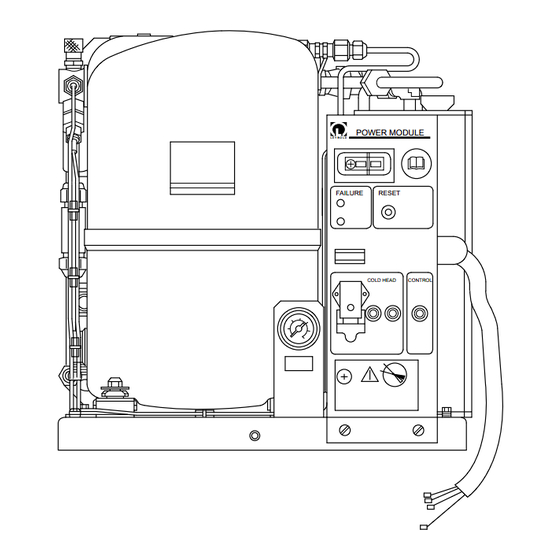
L E Y B O L D FAILURE RESET COLD HEAD CONTROL Fig. 2 RW 6000-1 compressor unit; front side 1 Description 1.1 Design and Function Cryogenic refrigeration units comprise: – the compressor unit, Compressor units are used to compress helium gas which is then vaporized in the cold head to produce low –... - Page 4 = High pressure = Low pressure DN = Nominal diameter Fig. 3 Flow chart for the RW 6000-1 compressor unit Figure 3 shows the flow diagram for a compressor unit. The helium gas exiting the second oil separator will still The oil-lubricated, hermetically sealed helium compres- contain small quantities of oil vapor.
-
Page 5: Standard Equipment
Description Safety Equipment Safety equipment Indication at the compressor unit Pressure switch (PSL1): Pressure differential between low- LOW PRESSURE LED lights ±0,5 pressure helium and atmospheric pressure < 1,5 bar (22 psi) Thermal switch (TSH1): helium temperature following TEMPERATURE LED lights the heat exchanger >... -
Page 6: Technical Specifications
Description 1.3 Technical Specifications 1.4 Order Information Helium filling pressure at room temp. Cat.-No. Operation at 50 Hz Compressor unit, RW 6000-1 891 44 psig 218 to 232 Operation at 60 Hz Adsorber, ARW 2 891 84 psig 189 to 203... -
Page 7: Installation
Installation 2 Installation 2.1 Safety Information The owner/operator shall ensure that the compressor Warning units are operated only by persons who have been These compressor units shall not be used instructed in their use and that they are serviced only by in an environment subject to explosion qualified technicians;... - Page 8 Installation POWER MODULE L E Y B O L D FAILURE RESET COLD HEAD CONTROL LOW PRESSURE HIGH PRESSURE L E Y B O L D Key to Fig. 4 1 Master switch 2 Electrical connection for the cold OUTLET head 3 Pressure gauge COOLING...
-
Page 9: Unpacking And Inspecting
More severe angles could result in damage to the com- Warning pressor capsule or oil contamination in the helium circuit. The RW 6000-1 is not equipped with a Check the pressure level indicated at the pressure gauge safety guard (type of protection IP 21); it attached to the compressor;... -
Page 10: Coolant Connection
(water hardness) should be peratures are below 5°C (40°F). If you use anti-freeze, 1.25 to 1.8 mmol/l. please consult Leybold as to the proper choice of agent. 1 mmol/l = 5.5° d (German hardness scale) The specific thermal capacity, viscosity, and the corros- = 7.02°... -
Page 11: Electrical Connection
Installation Maximum Gal/min l/min Permissible range New heat exchanger Gal/min l/min Calcium-clogged heat exchanger 30 °C Pressure differential between water inlet and outlet °F Coolant inlet temperature Fig. 5 Charts: Coolant criteria 2.5 Electrical Connection To do so, loosen the screws which hold the power mo- dule on the base plate and pull out the power module. -
Page 12: Mounting The Flexlines
Follow the instructions for the work. Use only the supplied open-end wrenches, or open-end wrenches approved by Leybold, to mount flexlines. Connect the flexlines in sequence, (8/1) to (8/4), corre- sponding to the direction in which the helium flows. - Page 13 Installation Attaching coupling to the cold head Attaching coupling to the compressor unit hold turn hold turn Cold head Compressor unit “ 1“ “ 1 “ “ 1“ “ “ (27) (27) Unscrewing coupling from the compressor unit Unscrewing coupling from the cold head break hold hold...
- Page 14 Installation LOW PRESSURE HIGH PRESSURE L E Y B O L D OUTLET COOLING WATER INLET Attached to Flexline Color connection Color ———————————————————————— High-pressure Compressor high-pressure High-pressure Cold head- high-pressure Low-pressure green Low-pressure cold head green Low-pressure green Low-pressure compressor green Fig.
-
Page 15: Start-Up
Check the mains connection for correct phase sequence Caution each time the unit is connected to the power supply and If the RW 6000-1 is connected to 60 Hz line following every modification of the electrical connections. voltage, the helium filling pressure may not exceed 14 bar at room temperature. -
Page 16: Operation
Leybold Service Department. If the temperature of the compressor motor is too high, the compressor unit will be switched off without indica- Safety devices are integrated into the compressor unit to tion of the malfunction. -
Page 17: Shut-Down
Operation Key to Fig. 9 Master switch Indicator: Helium too warm Reset button Indicator: Insufficient pressure Operating hours meter Circuit breaker for control voltage Circuit breaker for cold head Pressure gauge POWER MODULE L E Y B O L D FAILURE RESET COLD HEAD... -
Page 18: Maintenance
Any work which is not described in these operating Caution instructions may be carried out only by the Leybold Ser- Only helium of the highest purity (99.999% vice Department or by personnel specially trained by or better) shall be used. - Page 19 Maintenance Pressure gauge Pressure gauge Helium filling with Swagelock connector and self-sealing coupling Compressor unit Helium filling Shut-off valve connection with self- sealing coupling Pressure reducer Helium supply cylinder Fig. 10 Topping up the helium filling helium filling nipple (11/1). Refill the compressor unit up to nominal value.
-
Page 20: Replacing The Adsorber
2.6. Caution When making this replacement use only the Unscrew the high-pressure flexline from the compressor appropriate adsorber supplied by Leybold; unit (11/3). refer to Section 1.4. Loosen the nut (11/5) with a 13-mm open-end wrench. Switch off the compressor unit in preparation for re- Use the assembly wrench supplied to detach the self- placing the adsorber. - Page 21 Maintenance Seal the old adsorber with the protective caps and for- ward it to Leybold for reconditioning. Warning The adsorber contains pressure of up to 16 bar (232 psig) even after it is removed from the system. Reattach the high-pressure flexline to the compressor unit.
-
Page 22: Troubleshooting
Check the setting of the motor protection switch Wiring and correct, if necessary. If the switch trips again at diagram the next starting attempt, notify the Leybold Service Department. Helium compressor is overheated. Eliminate the cause of the malfunction; see mal- function 6. - Page 23 Notes GA 12.107/5.02 - 12/97...
-
Page 24: Spare Parts
Spare parts 6 Spare Parts POWER MODULE L E Y B O L D FAILURE RESET COLD HEAD CONTROL Front view RW 6000-1 Lateral view RW 6000-1 Top view RW 6000-1 Power Module GA 12.107/5.02 - 12/97... - Page 25 200 80 418*) Automatic circuit breaker 200 80 417*) 200 80 583*) components identified with an asterisk *) may be replaced only by the LEYBOLD service department or by personnel specially trained by LEYBOLD for this work GA 12.107/5.02 - 12/97...
- Page 26 EC Conformance Declaration We, the Leybold Vacuum GmbH, declare herewith that The products comply with the following guidelines: the products listed below, on the basis of their design • EC Machinery Guidelines (89/392/EEC) and engineering as well as in the embodiment which we...
- Page 27 These Leybold compressor units have been registered for the Canadian Standards Association. under GS certificate No. S 9319521 01. The overall system comprises the RW 6000-1 compres- The label is applied to the data plate on the compressor sor unit with the 2 Adsorber and one or more “...
- Page 28 LEYBOLD VAKUUM GmbH Bonner Strasse 498 (Bayenthal) D-50968 Cologne Tel.: + 49 (221) 347-0 Fax: + 49 (221) 347-1250 http://www.leyboldvac.de e-mail:documentation@leyboldvac.de...
Need help?
Do you have a question about the RW 6000-1 and is the answer not in the manual?
Questions and answers