Table of Contents
Advertisement
Quick Links
Advertisement
Table of Contents

Summary of Contents for Sound Devices CL-16
- Page 1 C L - 1 6 LINEAR FADER CONTROL SURFACE FOR 8-SERIES MIXER-RECORDERS...
- Page 2 If you wish to discard a Sound Devices product in Europe, CL-16 User Guide | Rev 4/24/20 contact Sound Devices (Germany) for further information. This document is distributed by Sound Devices, LLC in online electronic (PDF) format only. Published in the USA. This table provides the revision history and cross-reference links to “what’s new”...
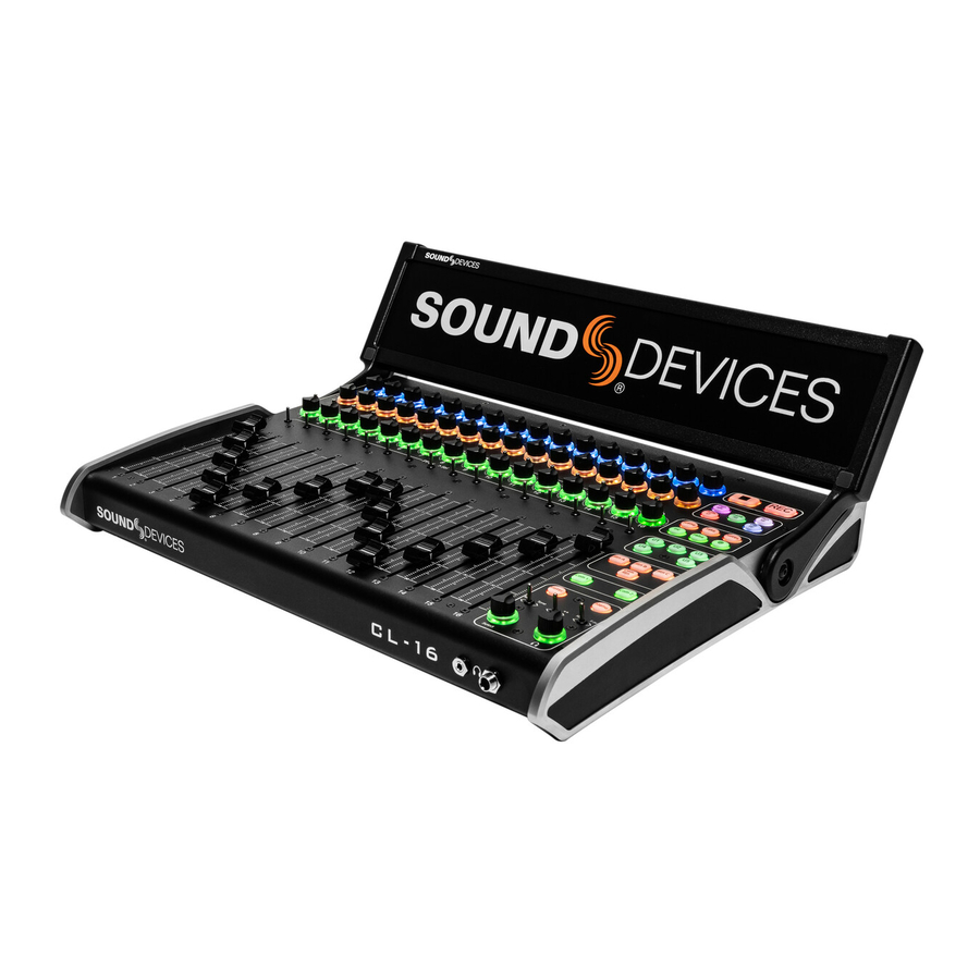
- Page 3 Welcome to the CL-16 The CL-16 Linear Fader Control Surface for 8-Series combines the simplicity of traditional analog consoles with the power and flexibility of digital consoles. This bespoke control surface enhances the experience of cart-based mixing with its intuitive operation, 16 silky-smooth faders, 16 dedi- cated trims, and a glorious panoramic LCD.
-
Page 4: Table Of Contents
Table of Contents PANEL VIEWS LCD DISPLAY CONNECTING THE CL-16 POWER ON/OFF UNPLUGGING CL-16 UPDATING FIRMWARE OPERATIONAL OVERVIEW CHANNEL STRIP MODES/METER VIEWS ANALOG FEEL OUTPUTS TRANSPORT CONTROL MODE BUTTONS METADATA BUTTONS USER ASSIGNABLE BUTTONS RETURN/COM BUTTONS METER BUTTON MENU BUTTON... -
Page 5: Panel Views
Values and status are displayed on the second row User-mappable to various functions for fast access of the LCD. Rotate or press to adjust or toggle different parameters. Mapped functions are displayed above in the LCD. The surrounding ring LEDs display various status information. CL-16 User Guide... - Page 6 Hold then press a channels’ trim pot transport, timecode, metadata and more. to mute that channel. Also used to mute buses LCD Brightness is set in the Menu>Controllers>CL-16>LCD and outputs in relevant modes Brightness menu. 15. TOGGLE SWITCHES Duplicates the assigned functions of the three toggle switches below the 8-Series front panel LCD.
- Page 7 Panel Views BOT TOM Removable screws for service panel 1/4” 20 screw hole for mounting CL-16 User Guide...
- Page 8 4-pin XLR (M) programmable for peripherals Mixer-Recorder 8-Series Mixer-Re- accepts 10- input/output corder 18 V DC pins for remote control 1/4” TRS Jack Mappable Foot Pedal Control FRO NT 1/8” TRS Jack 1/4” TRS Jack Headphone Headphone Output Output CL-16 User Guide...
-
Page 9: Lcd Display
Channels with the same color indicator are grouped. Choose which color applies to a 9. TAKE NUMBER group in the CL-16>Group Color menu. Display and edit the current Take number. Press Stop 22. METER VIEW NAME while stopped to display the next Take number. -
Page 10: Power On/Off
23. DRIVE/POWER INFO AREA • Displays SSD, SD1, and SD2 remaining record time. • Displays 8-Series and CL-16 power source health and voltage. CL-16 User Guide... -
Page 11: Unplugging
8-Series The CL-16 can be plugged/unplugged from the 8-Series while pow- ered on with no damage to either unit. When the CL-16 is unplugged, “Control Surface Unplugged” is displayed in the 8-Series LCD. No levels will change. At this point: Select OK to continue without the control surface. -
Page 12: Operational Overview
Operational Overview The CL-16 combines the paradigm of a traditional mixer channel strip with the multi-function capability of a modern digital mixer. Once you become familiar with the various controls, different modes and their asssociated meter views, the vast potential of your 8-Series mixer/recorder will become apparent. -
Page 13: Modes/Meter Views
Modes/Meter Views BUSES Press to display Bus 1-10, L, R meters on the CL-16 LCD and Bus Routing screens on the 8-series LCD Bus button illuminates light pink. Rotate middle The CL-16 has various operation modes (listed below). knobs to adjust Bus L, R, B1 - B10 master gains; move Changing a mode changes the function of the multi-function a toggle left to solo a bus;... - Page 14 Ch Name: Press knob to bring up the channel’s Edit Channel Name virtual keyboard in the 8-Series display. Use a USB keyboard or the Select Knob, HP knob, and Toggle switches near the bottom right hand corner of the CL-16 to edit channel (track) name.
-
Page 15: Analog Feel
(PFLs), and mutes. INC Press to increment the scene name. Requires that the By setting the CL-16 to an EQ mode e.g. LF EQ (Hold Bank then Arm), the channel strip’s upper and middle knob give Files>Scene Increment Mode is set to Character or Numeric. -
Page 16: Specifications
Specifications Specifications are subject to change without prior notice. For the latest information available on all Sound Devices products, visit our website: www.sounddevices.com. VOLTAGE 10-18 V DC at XLR-4. Pin 4 = +, pin 1 = ground. CURRENT DRAW (MIN) -
Page 17: Servicing Faders
Servicing Faders The CL-16 features field-serviceable Penny & Giles faders. The faders can be quickly changed with minimal effort. TO REMOVE A FADER : STEP 1 Remove fader knob by gently pulling up. STEP 2 Remove the screws that hold the fader in place. One above and one below the fader. - Page 18 STEP 3 Flip the unit over to access the fader port. Remove the two screws and remove the cover. STEP 4 Disconnect the fader electrical connections by pulling gently. CL-16 User Guide...
- Page 19 TO INSTALL A NEW FADER REVERSE THE PREVIOUS STEPS: STEP 6 Insert the fader. STEP 7 Reconnect the fader electrical connections. STEP 8 Replace the rear panel and back access screws. STEP 9 Replace the two fader screws. STEP 10 Replace the fader knob. CL-16 User Guide...
-
Page 20: Declaration
2011/65/EU The following harmonized standards and/or normative documetns were applied: Safety EN 62368-1:2014 EN 55032:2015, Class B EN 55035:2017 This Declaration of Conformity applies to the above-listed product(s) placed on the EU market after: April, 15 2020 CL-16 User Guide... - Page 21 HOWEVER CAUSED AND ON ANY THEORY OF LIABILITY, WHETHER IN CONTRACT, STRICT LIABILITY, OR TORT (INCLUDING NEGLIGENCE OR OTHERWISE) ARISING IN ANY WAY OUT OF THE USE OF THIS SOFTWARE, EVEN IF ADVISED OF THE POSSIBILITY OF SUCH DAMAGE. CL-16 User Guide...
- Page 22 Post Office Box 576 E7556 State Rd. 23 and 33 Reedsburg, Wisconsin 53959 USA support@sounddevices.com +1 608.524.0625 main +1 608.524.0655 fax 800.505.0625 toll free www.sounddevices.com...
Need help?
Do you have a question about the CL-16 and is the answer not in the manual?
Questions and answers