Table of Contents
Advertisement
Available languages
Available languages
Quick Links
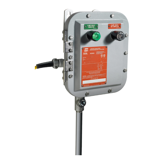
EGL Grounding Indicator with Automatic
Pump Control and Ground Verification System
Installation & Maintenance Information
APPLICATION
EGL Grounding Indicators are to be permanently mounted in a secure
location adjacent to loading/unloading area. EGL Grounding Indicators
are connected to tank vehicles, drums, or other containers before
beginning transfer of combustible materials. While connected, the EGL
grounds static electricity and continuously verifies the presence of a static
grounding system. The EGL can be installed to actuate remote devices
(lights, horns) to announce that a safe static ground has been
established, or to send an alarm when the ground is interrupted. An EGL
Grounding Indicator is recommended to be used in the control circuit of a
pump to prevent it from being started until the static grounding circuit is
completed, and to shut down the pump automatically if the static
grounding circuit is disconnected.
INSTALLATION
To provide protection against fire or shock hazard, the electrical
power must be OFF before and during installation and
maintenance.
To ensure proper operation of the EGL210, two separate ground
leads from the electrical supply panel must be provided: one to
terminal #3 and the other to the green ground lug on the
enclosure interior. This provides a continuity check to verify the
EGL210 is grounded.
WEIGHT = 32 lbs (14.5 kg)
IF 1512 • 11/11
SAVE THESE INSTRUCTIONS FOR FUTURE REFERENCE
WARNING
CAUTION
DIMENSIONS - INCHES (CENTIMETERS)
Copyright © 2011, Cooper Industries, Inc.
EGL Grounding Indicators are suitable for use in Class I, Groups B, C, D;
Class II, Groups F, G, and Class III hazardous (classified) areas as
defined by the National Electrical Code (NEC).
EGL Grounding Indicators should be installed, inspected, and serviced by
qualified and competent personnel.
Read all instructions before starting installation of this product.
Contact your Crouse-Hinds sales representative, Customer Service, or
your Crouse-Hinds distributor if you have any questions.
1.
Select a mounting location that will provide suitable strength and
rigidity for supporting the enclosure, all contained wiring and
control devices. Figure 1 shows mounting dimensions.
•
Hazardous location information specifying Class and Group
listing is marked on the enclosure nameplate.
•
Conduit sealing fittings must be installed in accordance
with Section 501 of the National Electrical Code. An
appropriate seal shall be installed within 18" (45.7 cm) of the
enclosure for Groups B.
•
All unused conduit openings must be plugged. Plug must
engage a minimum of five full threads and be a minimum of
1/8" (.318 cm) thick.
FIGURE 1
IF 1512
CAUTION
Page 1
Advertisement
Table of Contents

Summary of Contents for Cooper Crouse-Hinds EGL Series
- Page 1 EGL Grounding Indicator with Automatic Pump Control and Ground Verification System Installation & Maintenance Information IF 1512 SAVE THESE INSTRUCTIONS FOR FUTURE REFERENCE APPLICATION EGL Grounding Indicators are to be permanently mounted in a secure EGL Grounding Indicators are suitable for use in Class I, Groups B, C, D; location adjacent to loading/unloading area.
- Page 2 Securely fasten enclosure to the mounting location, then attach CAUTION into conduit system. • Before assembling any mating threads, make certain that If remote indicating systems are used, be sure they comply with there is no dirt or other foreign material on, or in, either set of threads.
-
Page 3: Maintenance
When the grounding clamp is connected to a dispensing or WARNING receiving vessel and the ground circuit is completed, auxiliary If any part of the grounding indicator or total installation contacts between terminal block positions 4 & 6 and 7 & 9 will appears to be broken or damaged, be OPEN. -
Page 4: Installation
Indicateur de mise à la terre EGL avec commande de pompe automatique et un système de vérification à la terre IF 1512 Information pour l’installation & l’entretien CONSERVEZ CES INSTRUCTIONS POUR RÉFÉRENCE FUTURE APPLICATION Les indicateurs de mise à la terre EGL doivent être installés en Les indicateurs de mise à... - Page 5 Attachez solidement l’enceinte à un socle et ensuite, au système de ATTENTION conduit. • Avant d’assembler tous les fils conjugués, assurez-vous qu’il n’y Si des circuits de signalisation à distance sont utilisés, assurez-vous a aucune saleté ou corps étrangers sur, ou à l’intérieur, de l’un qu’ils soient conforment aux conditions du NEC, qu’ils assurent la ou l’autre ensemble de fils.
-
Page 6: Entretien
Lorsque la pince de la mise à la terre est branchée à un récipient de AVERTISSEMENT distribution ou de réception et que le circuit de mise à la terre est Si n’importe quelle partie de l’indicateur de mise à la terre ou l’installation complet, les contacts auxiliaires entre les position 4 &... -
Page 7: Instalación
Contacte con su Representante de Ventas, con el Servicio al Cliente, o estática se haya completado, y para apagar la bomba automáticamente si con su Distribuidor de Cooper Crouse-Hinds en caso de tener alguna el circuito de puesta a tierra estática se desconecta. - Page 8 Ajuste firmemente el gabinete a su lugar de montaje, y a ADVERTENCIA continuación conéctelo al sistema del conducto. • Antes de ensamblar las roscas de acoplamiento, asegúrese de Si los sistemas indicadores remotos están en uso, asegúrese de que no haya suciedad u otros materiales extraños sobre la que cumplen con los requerimientos del NEC, garantizan la superficie o dentro de ningún juego de roscas.
-
Page 9: Mantenimiento
Cuando la abrazadera de la puesta a tierra está conectada a un ADVERTENCIA recipiente dispensador o receptor, y el circuito puesto a tierra se ha Si alguna parte del indicador de la puesta a tierra o de la instalación total completado, los contactos auxiliares entre las posiciones 4 y 6, y las parece estar quebrada o dañada, posiciones 7 y 9 del bloque de terminales estarán ABIERTOS.
Need help?
Do you have a question about the EGL Series and is the answer not in the manual?
Questions and answers