Code: 101157 with Spiral Blades
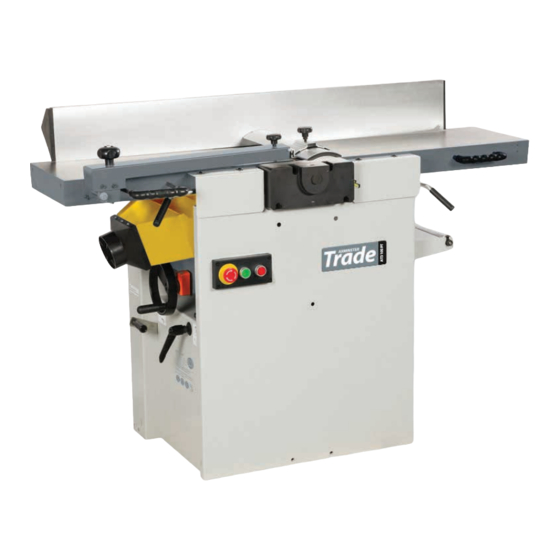
AT260PT / AT260SPT
AT310SPT
Planer Thicknesser
AT260PT Code 508498
AT260SPT Code 101156
AT310SPT Code 101157
Code: 508498 with HSS Blades
Code: 101156 with Spiral Blades
Original Instructions
AT&M: 14/09/2018
BOOK REF : 101612


Need help?
Do you have a question about the AT260PT and is the answer not in the manual?
Questions and answers