Advertisement
Quick Links
Carbon Monoxide Transmitter
Before Installation
Read these instructions carefully before installing and commissioning the CO Transmitter. Failure to follow these instructions
may result in product damage. Do not use in an explosive or hazardous environment, with combustible or flammable gases,
as a safety or emergency stop device or in any other application where failure of the product could result in personal injury.
Take electrostatic discharge precautions during installation and do not exceed the device ratings.
Mounting
The CO enclosure should be mounted onto a flat surface three to five feet from the floor of the area to be controlled. The
mounting hole locations are shown in the enclosure dimensional drawings. Do not mount the sensor near doors, opening
windows, supply air diffusers or other known air disturbances. Avoid areas with vibrations or rapid temperature changes.
Open the hinged cover by releasing the latch and connect the device according to the wiring instructions. After wiring and
setup are complete, close and latch the cover. The cover may be secured with two self-tapping screws in the holes provided.
Hardware Setup
The only hardware setup required is to select the analog output type with the pcb switch labelled VOLT and mA. Slide the
switch to the correct position for the required output signal type, either 4-20 mA or 0-5/10 Vdc.
Power and Analog Output Wiring
Use 22 AWG shielded wire for all connections and do not locate the device wires in the same conduit with wiring used to
supply inductive loads such as motors. Disconnect the power supply before making any connections to prevent electrical
shock or equipment damage. Make all connections in accordance with national and local codes.
The wiring configuration depends on the specific model and the installed options. Follow the example wiring diagrams to
determine the correct wiring. All models have the same terminal functions. This device has a half-wave type power supply so
the power supply common is the same as the output signal common. Therefore, several devices may be connected to one
power supply and the output signals all share the same signal common. Use caution when grounding the secondary of an AC
transformer or when wiring multiple devices so that the circuit ground point is the same on all devices and the controller.
In general, the transformer should NOT be connected to earth ground when using devices with RS-485 network connections.
This is a 3-wire sourcing device. All models require a 24 Vac/dc power supply to operate. Connect the positive dc voltage or
the hot side of the ac voltage to the ANALOG - PWR terminal and the power supply common to the ANALOG - COM
terminal. Note that the Analog COM terminal is NOT connected to the Relay COM terminals. The device is reverse voltage
protected and will not operate if the power supply is connected backwards.
The linear output signal (either 4-20 mA or 0-5/10 Vdc) is available on the ANALOG - CO terminal. The signal is
referenced to the Analog COM terminal. The 4-20 mA output signal operates in the Active mode and does not require a loop
power supply. This means the signal current is generated by the transmitter and must not be connected to a powered
May 5, 2017
Introduction
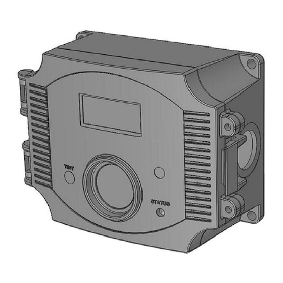
The CO Transmitter uses an electrochemical sensor to monitor the
carbon monoxide level and outputs a field-selectable 4-20 mA or
voltage signal. The voltage signal may also be set to 0-5 or 0-10
Vdc. The sensing range and output may be scaled to either 100,
150, 300, 400 or 500 ppm via the on-board menu. A front panel
LCD is standard to ensure easy setup and operation.
Other standard features include a back light for the LCD, a front
panel test switch, status indication and an alarm buzzer. The test
function may also be controlled remotely with a digital input signal.
A three-key menu is implemented to allow local configuration of all
device parameters.
Optional features include one or two alarm relays and RS-485
network communications configured for either ModBus or BACnet
protocols.
IN-CMD5B4MOD-01-01
Modbus
Installation Manual
Page 1
Advertisement

Related Manuals for Greystone CMD5B4 Series


Summary of Contents for Greystone CMD5B4 Series
- Page 1 Carbon Monoxide Transmitter Modbus Installation Manual Introduction The CO Transmitter uses an electrochemical sensor to monitor the carbon monoxide level and outputs a field-selectable 4-20 mA or voltage signal. The voltage signal may also be set to 0-5 or 0-10 Vdc.
-
Page 2: Alarm Relay Wiring
Carbon Monoxide Transmitter Modbus Installation Manual input or device damage will result. This is the typical operating mode of a “three-wire device”. Ensure the controller Analog Input (AI) matches the CO Transmitter output signal type before power is applied. The current signal has a maximum load that it will drive and the voltage output has a minimum load. - Page 3 Carbon Monoxide Transmitter Modbus Installation Manual Product Drawings Wiring Examples May 5, 2017 IN-CMD5B4MOD-01-01 Page 3...
-
Page 4: Operation - Start-Up
Carbon Monoxide Transmitter Modbus Installation Manual Operation - Start-up Verify that the CO Transmitter is properly wired according to the wiring diagrams and all connections are tight. Ensure the output switch is in the correct position for either voltage or mA. Apply power to the device. The device will initially start up in warm-up mode which lasts for about two minutes. -
Page 5: Network Communication
Carbon Monoxide Transmitter Modbus Installation Manual be cancelled by pressing the TEST switch a second time. Test mode cannot be activated if the device is in Fault, Alarm or Re-Cal modes of operation, only in Normal mode. The Test function is useful to verify the output and alarm relay operation and the Test time can be programmed via the menu. - Page 6 Carbon Monoxide Transmitter Modbus Installation Manual <MENU> 4. Buzzer Use the <ROLL> key to scroll through the available options. The buzzer delay may be set from 0 to 10 Del 5Min minutes in 1 minute increments. Press <SAVE> to save the setting. The factory default is 5 minutes. This item will not be shown if the buzzer is disabled.
- Page 7 Carbon Monoxide Transmitter Modbus Installation Manual initiate the test function. Note that the test mode will only function is the device is operating in the Normal mode, the test function cannot be initiated if any alarm is present. Press <SAVE> to save the setting. <MENU>...
- Page 8 Carbon Monoxide Transmitter Modbus Installation Manual 23. BackLite Use the <ROLL> key to enable or disable the LCD backlight. When enabled the backlight is always on and Enable when disabled it never lights. Press <SAVE> to save the setting. The factory default is Enable. <MENU>...
- Page 9 Carbon Monoxide Transmitter Modbus Installation Manual The next steps are only shown if the BACnet communication protocol is installed. 33. BACnet Press the <ROLL> key to select a unique network address from 0-127, then <SAVE> the value. The Addr 4 factory default BACnet MAC address is 4.
- Page 10 Carbon Monoxide Transmitter Modbus Installation Manual Calibration The CO transmitter features a cover mounted sensor pcb that is pre-calibrated. This means that the entire sensor pcb can simply be replaced with a new calibrated pcb if desired without having to remove the enclosure and the main processor board.
- Page 11 Carbon Monoxide Transmitter Modbus Installation Manual Specifications Measurement ....Electrochemical Sample Method ....Diffusion Measurement Range .
-
Page 12: Modbus Trouble-Shooting
Carbon Monoxide Transmitter Modbus Installation Manual Network Communication The device parameters must be set before connection to the network and will ensure each device will have a unique ModBus address for startup. Details of the device setup can be found in the User Menu section. Once set, all parameters are saved in non-volatile memory. -
Page 13: Modbus Register Addressing
Carbon Monoxide Transmitter Modbus Installation Manual ASCII Mode Message Format Modbus Framing ASCII characters 0…9, A…F start bits --- 1 data bits --- 7 Data Bits parity bits --- none, odd or even stop bits --- 1or 2 Baud Rate 300, 600, 1200, 2400, 4800, 9600 or 19200 Duplex Half duplex... - Page 14 Carbon Monoxide Transmitter Modbus Installation Manual Unsigned 16-bit integer 40009 Word 0x0000 = Buzzer Disable, 0x0001 = Buzzer Enable Unsigned 16-bit integer, BUZZER_TRIP = 0 to 0x0030 40010 Word TRIP = 20 + 10 * (BUZZER_TRIP) = 20 to 500 ppm Unsigned 16-bit integer, BUZZER_DELAY = 0 to 0x000A 40011 Word...
- Page 15 Carbon Monoxide Transmitter Modbus Installation Manual Function Codes (RTU mode) 0x03 --- Read holding registers Query Slave address Function Starting Starting Quantity of Quantity of (0x01 to 0xFF) code (0x03) address MSB address LSB registers MSB registers LSB * Starting address = 0x0000 to 0xFFFF, Quantity of registers = 0x0000 to 0x007D Response Slave address Function...
- Page 16 Carbon Monoxide Transmitter Modbus Installation Manual 0x03 --- Read CO PPM Query Slave address 0x03 0x00 0x01 0x00 0x01 (0x01 to 0xFF) Response Slave address Register value Register value 0x03 0x02 (0x01 to 0xFF) MSB (PPM) LSB (PPM) * Register value = 0x0000 to 0x01F4, corresponding to 0 to 500 ppm 0x03 --- Read Temperature Query Slave address...
- Page 17 Carbon Monoxide Transmitter Modbus Installation Manual 0x03 --- Read Relay 2 Status Query Slave address 0x03 0x00 0x05 0x00 0x01 (0x01 to 0xFF) Response Slave address Register value Register value 0x03 0x02 (0x01 to 0xFF) 0x00 * Register value = 0x0000 = relay 2 not activated, 0x0001 = relay 2 activated 0x03 --- Read Test Mode Status Query Slave address...
- Page 18 Carbon Monoxide Transmitter Modbus Installation Manual 0x06 --- Write single register (BUZZER_DELAY) Query Slave address Register 0x06 0x00 0x0A 0x00 (0x01 to 0xFF) value LSB Response Slave address Register 0x06 0x00 0x0A 0x00 (0x01 to 0xFF) value LSB * Register value = 0x0000 to 0x000A, corresponding to 0 to 10 minutes 0x06 --- Write single register (RELAY1_TRIP) Query Slave address...
- Page 19 Carbon Monoxide Transmitter Modbus Installation Manual 0x06 --- Write single register (RELAY2_HYST) Query Slave address Register 0x06 0x00 0x0F 0x00 (0x01 to 0xFF) value LSB Response Slave address Register 0x06 0x00 0x0F 0x00 (0x01 to 0xFF) value LSB * Register value = 0x0000 to 0x0012, corresponding to 10 to 100 ppm, HYST = 10 + 5 * (RELAY2_HYST) 0x06 --- Write single register (RELAY2_DELAY) Query Slave address...
- Page 20 Carbon Monoxide Transmitter Modbus Installation Manual 0x06 --- Write single register (FAULT_TIME) Query Slave address Register 0x00 0x14 0x00 0x06 (0x01 to 0xFF) value LSB Response Slave address Register 0x06 0x00 0x14 0x00 (0x01 to 0xFF) value LSB * Register value = 0x0000 to 0x0003, corresponding to 3 to 6 years, TIME = 3 + (FAULT_TIME) 0x06 --- Write single register (DISPLAY_MODE) Query Slave address...
- Page 21 Carbon Monoxide Transmitter Modbus Installation Manual 0x06 --- Write single register (RECAL_MODE_ENABLE) Query Slave address Register 0x06 0x00 0x18 0x00 (0x01 to 0xFF) value LSB Response Slave address Register 0x06 0x00 0x18 0x00 (0x01 to 0xFF) value LSB * Register value = 0x0000 = ReCal mode disable, 0x0001 = ReCal mode enable, 0x0002 = ReCal mode reset, revert to enable 0x06 --- Write single register (RECAL_TIME) Query...
- Page 22 Carbon Monoxide Transmitter Modbus Installation Manual Exception response Slave address Function Exception code * (0x01 to 0xFF) code + 0x80 0x01, 0x02 or 0x03 * An exception response is only returned if the CRC is correct Exception code 01 --- illegal function, 02 --- illegal address, 03 --- illegal data value Function codes (ASCII mode) 0x03 --- Read holding registers Query...
- Page 23 Carbon Monoxide Transmitter Modbus Installation Manual Exception response Start Slave address Slave address Function Function Exception code character (:) (0x01 to 0xFF) (0x01 to 0xFF) Code + 0x80 Code + 0x80 0x30 0x3A Exception code 0x01, 0x02 or 0x03 Return-line feed Return-line feed (0x31, 0x32 or 0x33) (CRLF) 0x0D...
- Page 24 Carbon Monoxide Transmitter Modbus Installation Manual 0x03 --- Read Temperature °C / °F Query Slave address Slave address 0x3A 0x01 to 0xFF 0x01 to 0xFF 0x30 0x33 0x30 0x30 0x30 0x32 0x30 0x30 0x30 0x31 LRC MSB LRC LSB 0x0D 0x0A Response Slave address...
- Page 25 Carbon Monoxide Transmitter Modbus Installation Manual 0x03 --- Read Relay 2 Status Query Slave address Slave address 0x3A 0x01 to 0xFF 0x01 to 0xFF 0x30 0x33 0x30 0x30 0x30 0x35 0x30 0x30 0x30 0x31 LRC MSB LRC LSB 0x0D 0x0A Response Slave address Slave address...
- Page 26 Carbon Monoxide Transmitter Modbus Installation Manual 0x06 --- Write single register (BUZZER_ENABLE) Query Slave address Slave address 0x3A 0x01 to 0xFF 0x01 to 0xFF 0x30 0x36 0x30 0x30 0x30 0x38 0x30 (buzzer disable) 0x30 0x30 0x30 LRC MSB LRC LSB 0x0D 0x0A 0x31 (buzzer enable)
- Page 27 Carbon Monoxide Transmitter Modbus Installation Manual 0x06 --- Write single register (RELAY1_TRIP) Query Slave address Slave address 0x3A 0x01 to 0xFF 0x01 to 0xFF 0x30 0x36 0x30 0x30 0x30 0x41 0x30 0x30 Register value Register value LSB LRC MSB LRC LSB 0x0D 0x0A Response...
- Page 28 Carbon Monoxide Transmitter Modbus Installation Manual 0x06 --- Write single register (RELAY2_TRIP) Query Slave address Slave address 0x3A 0x01 to 0xFF 0x01 to 0xFF 0x30 0x36 0x30 0x30 0x30 0x44 0x30 0x30 Register value Register value LSB LRC MSB LRC LSB 0x0D 0x0A Response...
- Page 29 Carbon Monoxide Transmitter Modbus Installation Manual 0x06 --- Write single register (TEST_MODE_ENABLE) Query Slave address Slave address 0x3A 0x01 to 0xFF 0x01 to 0xFF 0x30 0x36 0x30 0x30 0x31 0x31 0x30 (buzzer disable) 0x30 0x30 0x30 LRC MSB LRC LSB 0x0D 0x0A 0x31 (buzzer enable)
- Page 30 Carbon Monoxide Transmitter Modbus Installation Manual 0x06 --- Write single register (FAULT_TIME) Query Slave address Slave address 0x3A 0x01 to 0xFF 0x01 to 0xFF 0x30 0x36 0x30 0x30 0x31 0x34 0x30 0x30 0x30 Register value LSB LRC MSB LRC LSB 0x0D 0x0A Response...
- Page 31 Carbon Monoxide Transmitter Modbus Installation Manual 0x06 --- Write single register (OUTPUT_TEST) Query Slave address Slave address 0x3A 0x01 to 0xFF 0x01 to 0xFF 0x30 0x36 0x30 0x30 0x31 0x37 0x30 0x30 0x30 0x30 to 0x36 LRC MSB LRC LSB 0x0D 0x0A Response...
- Page 32 Carbon Monoxide Transmitter Modbus Installation Manual 0x06 --- Write single register (C/F) Query Slave address Slave address 0x3A 0x01 to 0xFF 0x01 to 0xFF 0x30 0x36 0x30 0x30 0x31 0x40 0x30 0x30 0x30 Register value LSB LRC MSB LRC LSB 0x0D 0x0A Response...
Need help?
Do you have a question about the CMD5B4 Series and is the answer not in the manual?
Questions and answers