Table of Contents
Advertisement
Quick Links
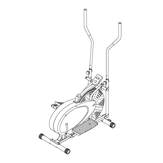
Elliptical Trainer
Manufactured for Bluestem Brands, Inc. by Body Flex Sports, Inc.
Product Code: QM893
Model #: BR1820
WARNING: MAXIMUM WEIGHT
CAPACITY IS 250 lbs.
PLEASE READ MANUAL CAREFULLY BEFORE ATTEMPTING TO ASSEMBLE OR USE
YOUR NEW EXERCISE EQUIPMENT. RETAIN FOR FUTURE USE.
* This item is for consumer use only and it is not meant for commercial use.
OWNER'S MANUAL / ASSEMBLY INSTRUCTION
Advertisement
Table of Contents

Related Manuals for Lifemax BR1820

Summary of Contents for Lifemax BR1820
- Page 1 Elliptical Trainer Manufactured for Bluestem Brands, Inc. by Body Flex Sports, Inc. Product Code: QM893 Model #: BR1820 WARNING: MAXIMUM WEIGHT CAPACITY IS 250 lbs. PLEASE READ MANUAL CAREFULLY BEFORE ATTEMPTING TO ASSEMBLE OR USE YOUR NEW EXERCISE EQUIPMENT. RETAIN FOR FUTURE USE.
- Page 2 PLEASE KEEP THESE INSTRUCTIONS FOR FUTURE USE & REFERENCE. DO NOT DISCARD. WARNING: SERIOUS INJURIES AND EVEN DEATH CAN OCCUR IF THE PROPER SAFETY PRECAUTIONS ARE NOT FOLLOWED. The diagram below highlights and reviews many of the important Safety and Warning labels also found on the unit.
-
Page 3: General Information
General Information Safety Storage and Use Before you undertake any exercise program, Your product is intended for use in clean please be sure to consult with your doctor. dry conditions. You should avoid storage in Frequent strenuous exercise should be excessively cold or damp places as this may approved by your doctor and proper use lead to corrosion and other related problems. - Page 4 Hardware & Tool List The following hardware is used to assemble your unit. Please take a moment to familiarize yourself with these items. Please note, most of these parts are already pre-assembled on your unit. Do not be alarmed if you see parts on this page that are not included in your hardware packet.
-
Page 5: Parts Listing
Parts Listing The following parts list describes all of the parts illustrated on the exploded diagram on the following page. Please note, most of these parts are already pre-assembled on your unit. Descriptoin Descriptoin 101B Main Frame Friction Belt (1150L mm) Front Stabilizer Tension Adjustment Knob Rear Stabilizer... -
Page 6: Exploded Diagram
Exploded Diagram The following diagram is provided to help you familiarize yourself with the parts and hardware that will be used during the assembly process. Please note that not all of the parts and hardware you see here will be used while you are assembling the machine because some of these items are already pre-installed. - Page 7 Assembly Instructions A s s e m b l y S t e p 1 Hardware & Tool Required Bolt With the help of an assistant, attach the Rear Stabilizer (#103) to the rear of the Main Frame (#101B). Insert two Carriage Bolts (#146) through the Rear Stabilizer (#103) followed by the rear of the Main Frame (#101B).
- Page 8 Assembly Instructions A s s e m b l y S t e p 2 Hardware & Tool Required Remove the Nylon Nuts (#145) and Washers (#156) that Washer are pre-assembled on the Handlebar Axle (#112) and set them aside as they will be used in a later process. Insert the Handlebar Axle (#112) through the main frame.
- Page 9 Assembly Instructions A s s e m b l y S t e p 3 Remove Hex Bolts (#105) and Nylon Nuts (#145) that are pre-assembled on the Pedal Connection Joint (#166A) and set them aside as they will be used in a later process. Attach the Pedal Connection Joint (#166A) to the Right Pedal Tube (#106R).
- Page 10 Assembly Instructions A s s e m b l y S t e p 3 IMPORTANT: Secure both pedal hinge bolts every 30 days. Through regular use, the pedal hinge bolts may still come loose even when the initial assembly was secure. DO NOT operate the Body Rider when these parts are loose! WARNING: Failure to keep these parts securely fastened will severely damage your Body Rider and may cause injury to the user.
- Page 11 Assembly Instructions A s s e m b l y S t e p 4 Hardware & Tool Required Attach the Right Pedal (#111) to the Right Pedal Tube Bolt (#106R) and secure them together using two Hex Bolts (#144) and two Nylon Nuts (#145). #144 Hex Bolt (M10x45 mm) [4 Pieces] Repeat this process on the other side.
- Page 12 Assembly Instructions Hardware & Tool Required A s s e m b l y S t e p 5 Bolt A. Handlebar Assembly: 1). Dual-action mode: To allow Left/Right Handlebar (#107L/107R) to move along with the movement of #157 Screw (M5x10 mm) [2 Pieces] the Pedals (#111), attach the Left/Right Handlebar (#107L/107R) to the Left/Right Coupler Bar (#104L Others...
- Page 13 Assembly Instructions T e n s i o n A d j u s t m e n t The assembly of your Body Rider is now complete. As you try it for the first time, you should adjust the tension to a desirable level before you begin a full workout.
-
Page 14: Safety And Maintenance
Safety & Maintenance SAFETY & WARNINGS • Make sure all nuts, bolts, and screws are tightened prior to use. • Be sure that all adjustment locking devices and safety devices are properly engaged prior to use! • Never over-tighten the above-mentioned devices and parts to avoid damage to the unit. •... -
Page 15: Computer Operation
Computer Operation SPECIFICATIONS: TIME………………………………………0:00-99:59 SPEED……………………………………0.0-99 Miles Per Hour DISTANCE ………………… …………0.0-999.9 MILES CALORIES…………………… …………0.0-9999CAL KEY FUNCTION: MODE: This key lets you select or set the display to the function of your choice. OPERATION PROCEDURES: 1. AUTO ON/OFF: ◆ The system turns on when any key is pressed or when it receives movement input from the speed sensor. - Page 16 Warm-Up Instructions Before use, you must read and understand all instructions & warning stated in this Owner's Manual as well as posted on the equipment. The following flexibility exercises are provided to you as a means to prevent injury while you are exercising. A proper warm-up routine decreases the chance of injuring your muscles while you are exercising.
- Page 17 Warm-Up Instructions Trunk Flexion, Prone 1. Assume the depicted position on your hands and knees. Stretch your hands out in front of you and then slowly start to pull them back in toward your body as you tuck your chin and arch your back upward. 2.
- Page 18 This page intentionally left blank...
-
Page 19: Proof Of Purchase
Proof of Purchase Model Number QM893 version: 01-03-2018 QM893... - Page 20 Made in China...
Need help?
Do you have a question about the BR1820 and is the answer not in the manual?
Questions and answers