
Summary of Contents for Quorum GRB-200
- Page 1 GRB-200 Demodulator (GOES-R) Operation, Installation, and Maintenance Manual Revision: A.01 Release Date: Quorum Communications, Inc. 3807 Carbon Rd. www.qcom.com Irving, TX 75038 USA...
- Page 2 GRB-200 Demodulator (GOES-R) OI&M © Copyright 2015, Quorum Communications, Inc. All rights reserved. This document may be freely distributed. Printed in the United States of America. Revision A.01 GRB-200 Demodulator (GOES-R) OI&M © Copyright 2015, Quorum Communications, Inc.
- Page 3 GRB-200 Demodulator (GOES-R) OI&M Version History Approved Approval Revision Implemented Revision Reason for Date Change Date A.01 M. Morgan 06/01/2015 A. Bundens 06/15/2015 New Document Revision A.01 GRB-200 Demodulator (GOES-R) OI&M © Copyright 2015, Quorum Communications, Inc.
- Page 4 GRB-200 Demodulator (GOES-R) OI&M This page intentionally left blank. Revision A.01 GRB-200 Demodulator (GOES-R) OI&M © Copyright 2015, Quorum Communications, Inc.
-
Page 5: Table Of Contents
4.4 DATA PROCESSING SUB-SYSTEM ................47 4.5 CONTROLLER SUB-SYSTEM ................... 48 SECTION 5 MAINTENANCE ................... 49 5.1 FUSE REPLACEMENT ....................49 5.1.1 Removing the Fuse Holder ..................50 5.2 PROBLEM RESOLUTION ................... 51 Revision A.01 GRB-200 Demodulator (GOES-R) OI&M © Copyright 2015, Quorum Communications, Inc. - Page 6 Figure 4 - Rubber Foot Pads and Screws (Bottom View of Unit) ......11 Figure 5 - Rack Mounting ................... 12 Figure 6 - GRB-200 Rear Input Panel Connections ........... 13 Figure 7 - Integrated Power Input Module ..............14 Figure 8 –...
-
Page 7: Introduction
The Quorum Communications GRB-200 (GOES-R) Dual Channel Demodulator is a key component of the Quorum GOES-R GRB Reception System and has been designed to work together with the Quorum Dual Polarity GRB Feed to provide the ultimate in GOES-R data reception. -
Page 8: Figure 3 - Grb-200 Functional Diagram
CADU frame formatting of the raw DVB-S2 data and streaming transmission of the CADU’s on Gigabit Ethernet via UDP. The output of the GRB-200 can be used directly by readily available community software to produce L1 and L2 data products. -
Page 9: Table 1 - Grb-200 Demodulator Specifications
Size 19” rack standard, 1U high, 10” deep Weight 10 lbs. 0 – 50 °C (32 to 122 °F) Operating Temperature Table 1 – GRB-200 Demodulator Specifications Revision A.01 GRB-200 Demodulator (GOES-R) OI&M © Copyright 2015, Quorum Communications, Inc. - Page 10 GRB-200 Demodulator (GOES-R) OI&M This page intentionally left blank. Revision A.01 GRB-200 Demodulator (GOES-R) OI&M © Copyright 2015, Quorum Communications, Inc.
-
Page 11: Installation
GRB-200 Demodulator (GOES-R) OI&M SECTION 2 INSTALLATION The GRB-200 is built in a 1U enclosure that can be mounted in a rack or used on a desktop. It is designed to operate in a standard office environment. 2.1 DESKTOP USE Four rubber foot pads must be installed on the bottom of the GRB-200 for desktop use (see Figure 4). -
Page 12: Rack Use
61 to 71 centimeters (19 x 24 to 28 inches). To mount the GRB- 200 in a rack, remove the four rubber foot pads and screws, and then attach the rack supports using the fasteners shown in Figure 5. Mount the GRB-200 with rack supports into the rack enclosure. -
Page 13: Connections
GRB-200 Demodulator (GOES-R) OI&M 2.3 CONNECTIONS Figure 6 - GRB-200 Rear Input Panel Connections The following connections are located on the rear panel of the GRB-200 Demodulator • AC Power Input (Integrated Power Input Module) • J01 – Feed Control (MS-Type Connection) •... -
Page 14: Integrated Power Input Module
(O) position, and then plug the IEC end of the power cord into the GRB-200 power plug. Plug the cord into a power source. The GRB-200 has an earth ground connector located near the power on/off switch. -
Page 15: J01 Feed Control
Figure 8 – J01 Feed Control Connection The Quorum GRB Reception Systems are provided with a pre-made interconnect cable for the Quorum GRB Feed. Connect this cable between the GRB Feed and the J1 Feed Control connector on the rear of the GRB Demodulator. -
Page 16: J02 Rs 232
The SD Card Slot is not used for normal operation. It is provided for test and diagnostic use during manufacture. Do not insert an SD Card in this slot as it could possibly interfere with the normal operation of the demodulator. Revision A.01 GRB-200 Demodulator (GOES-R) OI&M © Copyright 2015, Quorum Communications, Inc. -
Page 17: J03 Gb Ethernet
It is also possible to connect the GRB-200 to a gigabit Ethernet switch and set it to transmit multicast UDP messages to multiple servers simultaneously. In... -
Page 18: If Inputs
2.3.6 IF Inputs Figure 12 – J04 and J05 IF Input Connections The Quorum GRB Reception system is provided with pre-cut and terminated IF cables appropriate for the installation site. Route the supplied cables between the GRB Feed and the J04 and J05 IF inputs. Be sure to match the LHCP and RHCP outputs of the feed to the LHCP and RHCP inputs of the GRB Demodulator. -
Page 19: General Information
General Information Proper data interface operation requires matching the signal types and polarities of the GRB-200 to the input requirements of the interface. Refer to SECTION 3 for this information. After the GRB-200 has been installed and the cables have been connected, route the cables in a manner appropriate for safety, convenience, and to prevent them from becoming damaged. - Page 20 GRB-200 Demodulator (GOES-R) OI&M This page intentionally left blank. Revision A.01 GRB-200 Demodulator (GOES-R) OI&M © Copyright 2015, Quorum Communications, Inc.
-
Page 21: Operating Instructions
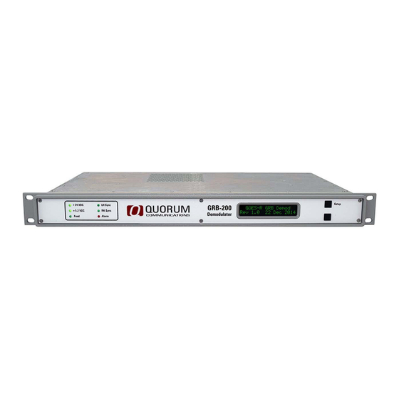
6 individual LED’s to indicate important status and 2 push button switches which are used to change the information displayed and configure the demodulator operation. Figure 13 - GRB-200 Demodulator Controls and Indicators 3.1.1 Status LED’s Six status LEDs are grouped on the left side of the front panel. -
Page 22: Push Button Switches
“Setting Defaults”. At this time all of the demodulator configuration data will be reset to the defaults. If you release both switches before the release message is displayed, the operation will be cancelled. Revision A.01 GRB-200 Demodulator (GOES-R) OI&M © Copyright 2015, Quorum Communications, Inc. -
Page 23: Lcd Display
During normal operation the 2 line LCD alternately displays the received signal level, lock status and Es/No (signal quality) of the LHCP and RHCP IF inputs. Alternate data is displayed here when in status, diagnostic or setup mode. Revision A.01 GRB-200 Demodulator (GOES-R) OI&M © Copyright 2015, Quorum Communications, Inc. -
Page 24: Configuring The Demodulator
• The UDP port for the Status data is set to 50030 • Both the LHCP and RHCP channels are set to transmit CADUs • Manufacturing and diagnostic test modes are disabled. Revision A.01 GRB-200 Demodulator (GOES-R) OI&M © Copyright 2015, Quorum Communications, Inc. -
Page 25: Using Setup To Configure The Demodulator
Press the bottom switch to choose 8PSK (default) or QPSK for the LHCP demodulator mode. Press the top switch to cycle to the RHCP setting. Press the bottom switch to choose 8PSK (default) or QPSK for the RHCP demodulator mode. Revision A.01 GRB-200 Demodulator (GOES-R) OI&M © Copyright 2015, Quorum Communications, Inc. -
Page 26: Figure 18 - Demodulator Spectrum Configuration Screenshot
(INVERTED) for the LHCP demodulator mode. Press the top switch to cycle to the RHCP setting. Press the bottom switch to choose NOR (NORMAL default) or INV (INVERTED) for the RHCP demodulator mode. Revision A.01 GRB-200 Demodulator (GOES-R) OI&M © Copyright 2015, Quorum Communications, Inc. -
Page 27: Figure 19 - Temperature Alarm Setting Screenshot
Press the top switch to cycle to the next display as shown below. Figure 20 - Exit Setup Screenshot If you don’t need to change the demodulator IP addresses you can choose to exit setup by pressing the lower switch. Revision A.01 GRB-200 Demodulator (GOES-R) OI&M © Copyright 2015, Quorum Communications, Inc. -
Page 28: Figure 21 - Demodulator Target Server Ip Address Screenshot
If the TO IP Address has been changed the message “Setting TO IP Addr” will be displayed and a short delay will occur while this address is changed in the Linux Data Processing Sub-system and the data processing tasks are restarted. Revision A.01 GRB-200 Demodulator (GOES-R) OI&M © Copyright 2015, Quorum Communications, Inc. -
Page 29: Figure 22 - Demodulators Ip Address Screenshot
After setting the MY IP Address, you will be given the option to exit or press the top switch to go to the start of setup. You can exit setup at any time by pressing and holding the top switch. Revision A.01 GRB-200 Demodulator (GOES-R) OI&M © Copyright 2015, Quorum Communications, Inc. -
Page 30: Normal And Diagnostic Display Modes
LK or UL: the demodulator status, LK – receiving DVB-S2 baseband packets or UL, unlocked Es/No: the signal to noise ratio of the signal, should be higher than 6.8 dB for error free data Revision A.01 GRB-200 Demodulator (GOES-R) OI&M © Copyright 2015, Quorum Communications, Inc. -
Page 31: Diagnostic And Status Displays
LO LK: The 280 MHz LO (Local Oscillator) status. LK – Locked (normal) or UL: unlocked (Alarm) Sn150503: the demodulator serial number R2.00: the demodulator controller sub-system firmware revision Revision A.01 GRB-200 Demodulator (GOES-R) OI&M © Copyright 2015, Quorum Communications, Inc. -
Page 32: Figure 25 - Demodulator Mode Spectrum And Agc Screenshot
AGC voltage. The GRB Demodulator has a reverse AGC (Automatic Gain Control). Maximum gain would be set with a voltage of 0.20 volts while higher voltages represent lower gain. Revision A.01 GRB-200 Demodulator (GOES-R) OI&M © Copyright 2015, Quorum Communications, Inc. -
Page 33: Figure 26 - General Feed Power Status Screenshot
Comm OK: the demodulator is receiving status messages from the GRB Feed This display is useful to know that the GRB Feed is connected, drawing the proper amount of power and is sending status data. Revision A.01 GRB-200 Demodulator (GOES-R) OI&M © Copyright 2015, Quorum Communications, Inc. -
Page 34: Figure 27 - General Grb Feed Status Screenshot
LO LK: The status of the GRB Feed LO (Local Oscillator) This display is useful to determine that the voltage drop to the feed from the demodulator is within specification and that the local oscillator is operating. Revision A.01 GRB-200 Demodulator (GOES-R) OI&M © Copyright 2015, Quorum Communications, Inc. -
Page 35: Figure 28 - Grb Feed Environmental Status Screenshot
The purge valve will close when the GRB Feed environment is OK. When the purge valve is open, the pressure reading will not be accurate. Revision A.01 GRB-200 Demodulator (GOES-R) OI&M © Copyright 2015, Quorum Communications, Inc. -
Page 36: Figure 29 - Demodulator Baseband Packet Status Screenshot
0. You can also compare the calculated Es/No to the actual Es/No of a properly calibrated DVB-S2 test signal. It is not necessary to transmit GRB data or CADUs for this display to be valid, only properly formatted baseband frames. Revision A.01 GRB-200 Demodulator (GOES-R) OI&M © Copyright 2015, Quorum Communications, Inc. -
Page 37: Receiving Grb Data
A free software package, CSPP Geo GRB, is available from the Space Science and Engineering group at the University of Wisconsin – Madison which can directly utilize the output of the Quorum GRB Demodulator. Revision A.01 GRB-200 Demodulator (GOES-R) OI&M... -
Page 38: Reading The System Status Data
Linux Data Processing Subsystem to be transmitted as a UDP packet to the TO IP address on port 50030. 3.5.1 Status Message The status message is formatted in XML as shown on the next page Revision A.01 GRB-200 Demodulator (GOES-R) OI&M © Copyright 2015, Quorum Communications, Inc. - Page 39 </RHCP> </DEMOD> <FEED> <Power val=" ON"/> <Current val="52mA"/> <Overcur val="No"/> <Comm val="OK"/> <Serialno val="150101"/> <Voltage val="23.4VDC"/> <LOlock val="LK"/> <Temp val="38C"/> <Hum val="35%"/> <Press val="0.4PSI"/> <Purge val="OPEN"/> </FEED> </GRB200> Revision A.01 GRB-200 Demodulator (GOES-R) OI&M © Copyright 2015, Quorum Communications, Inc.
- Page 40 RF Front End along with the received signal level (RSSI) for the LHCP and RHCP channels. The Atten (Attenuator) value is deprecated in this version and will always read Revision A.01 GRB-200 Demodulator (GOES-R) OI&M © Copyright 2015, Quorum Communications, Inc.
- Page 41 (8PSK), the spectrum inversion (NORMAL), the number of physical layer frames being received per second (PLFPS) and the number of BCH uncorrectable frames in the last second (BCHUC) for both the LHCP and RHCP demodulators. Revision A.01 GRB-200 Demodulator (GOES-R) OI&M © Copyright 2015, Quorum Communications, Inc.
- Page 42 Otherwise these fields will be NULL. To receive the status data, connect the gigabit Ethernet port of the GRB Demodulator to your Data Processing Server and read it from the appropriate UDP port. Revision A.01 GRB-200 Demodulator (GOES-R) OI&M © Copyright 2015, Quorum Communications, Inc.
-
Page 43: Theory Of Operation
THEORY OF OPERATION The GRB-200 Demodulator consists of a number of subsystems as shown below in Figure The RF Front End connects to the Quorum GRB Feed and provides RF filtering, gain and surge protection. The Demodulator Sub-system provides state of the art digital DVB-S2 signal demodulation. -
Page 44: Rf Front End
GRB-200 Demodulator (GOES-R) OI&M 4.1 RF FRONT END Figure 32 - GRB-200 Demodulator RF Section The RF Front End received the LHCP and RHCP IF signals from the GRB Feed and conditions these signals for use by the Demodulator Sub-system. The signal processing for the LH and RH channels is in most respects identical, so only one channel will be discussed. -
Page 45: Demodulator Sub-System
GRB-200 Demodulator (GOES-R) OI&M 4.2 DEMODULATOR SUB-SYSTEM Figure 33 - GRB-200 Demodulator Sub-System The Demodulator Sub-system converts the incoming processed 140 MHz IF signals to quadrature digital values and demodulates the incoming data. This process is identical for the LHCP and RHCP data so only one will be discussed. -
Page 46: Data Interface Sub-System
GRB-200 Demodulator (GOES-R) OI&M 4.3 DATA INTERFACE SUB-SYSTEM Figure 34 - GRB-200 Demodulator Data Interface Sub-System The Data Interface Sub-system accepts the burst baseband frame output of the Demodulator Sub-system and makes it available to the Data Processing Sub- system. This process is identical for the LHCP and RHCP signals so only one will be discussed. -
Page 47: Data Processing Sub-System
GRB-200 Demodulator (GOES-R) OI&M 4.4 DATA PROCESSING SUB-SYSTEM Figure 35 - GRB-200 Demodulator Data Processing Sub-System The Data Processing Sub-system consists of three main software tasks which read in and process the LHCP data, RHCP data and demodulator and feed status data, ultimately outputting UDP packets for use by the customer’s data processing... -
Page 48: Controller Sub-System
GRB-200 Demodulator (GOES-R) OI&M 4.5 CONTROLLER SUB-SYSTEM Figure 36 - GRB-200 Demodulator Controller Sub-System The Controller Sub-system is the heart of the GRB Demodulator. It is based on a PIC32 microcontroller running a proprietary control program. When the GRB Demodulator powers up, the controller first loads the necessary configuration data into the LHCP and RHCP demodulator ASICs. -
Page 49: Maintenance
5.1 FUSE REPLACEMENT Two (2) line input fuses are contained in the integrated power input module on the rear of the rack mount unit (see Figure 37). The GRB-200 primary power input requires two 5x20mm fast-acting fuses, two (2) amps. -
Page 50: Removing The Fuse Holder
2. Pinch together the retaining tabs and pull the fuse holder from the power input module (see Figure 39). Remove and replace the fuses. 3. Reinstall fuse holder in the power input module. Revision A.01 GRB-200 Demodulator (GOES-R) OI&M © Copyright 2015, Quorum Communications, Inc. -
Page 51: Problem Resolution
5:30 p.m. U.S. central time (GMT-006). Email: info@qcom.com; telephone: 972- 915-0256. To return a product, please contact the technical support team for a RMA number and shipping instructions. Revision A.01 GRB-200 Demodulator (GOES-R) OI&M © Copyright 2015, Quorum Communications, Inc. - Page 52 GRB-200 Demodulator (GOES-R) OI&M This page intentionally left blank. Revision A.01 GRB-200 Demodulator (GOES-R) OI&M © Copyright 2015, Quorum Communications, Inc.
- Page 53 GRB-200 Demodulator (GOES-R) OI&M This page intentionally left blank. Revision A.01 GRB-200 Demodulator (GOES-R) OI&M © Copyright 2015, Quorum Communications, Inc.
- Page 54 GRB-200 Demodulator (GOES-R) OI&M This page intentionally left blank. Revision A.01 GRB-200 Demodulator (GOES-R) OI&M © Copyright 2015, Quorum Communications, Inc.
Need help?
Do you have a question about the GRB-200 and is the answer not in the manual?
Questions and answers