Table of Contents
Advertisement
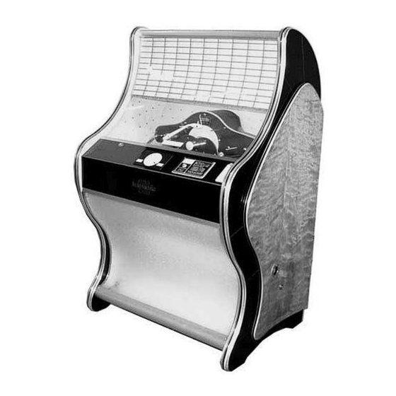
Music Maker 200
T200 Service Engineers Manual
Also Suitable for
Tonomat Telematic 200 and MM200
This Manual is an English Translation of the Tonomat Telematic 200 Manual, many
thanks to Stuart and Sue Saunders for undertaking the translation and for the
assistance from Hildegard Stamann for the additional amendments, information and
use of diagrams within the manual.
Various parts and complete printed and bound original manuals for Ditchburn and
Tonomat Jukeboxes can be purchased from
www.jukebox-world.de/en/Onlineshop/
More information on Ditchburn Jukeboxes can be found at
www.ditchburn.co.uk
Advertisement
Table of Contents

Summary of Contents for Ditchburn Music Maker 200
- Page 1 Stuart and Sue Saunders for undertaking the translation and for the assistance from Hildegard Stamann for the additional amendments, information and use of diagrams within the manual. Various parts and complete printed and bound original manuals for Ditchburn and Tonomat Jukeboxes can be purchased from www.jukebox-world.de/en/Onlineshop/ More information on Ditchburn Jukeboxes can be found at www.ditchburn.co.uk...
-
Page 2: Table Of Contents
CONTENT 1. Important data of the "telematic 200"………………………………………………… ……………………………………………………….. 2. Installation and operation 3. Description of the electrical functions when dialing……………………………… Coin………………………………………………………………………………….... Selection of the first digit…………………………………………………………………….. 5 Dial the second digit………………………………………………………………………. Dial the third digit………………………………………………………………………….. Raising the selector pin…………………………………………………………………… Reset the rotary selector………………………………………………………….... -
Page 3: Important Data Of The "Telematic 200
Important data The "telematic 200" Amplifier: Dimensions: 30 Watt high-performance Hi-Fi amplifier with Height: 145 cm connection option for additional speakers. Width: 94 cm Tubes: 1 x EZ 81, 4 X EL 84, 2 X ECC 81. Depth: approx. 73 cm A potentiometer serves as the volume control. -
Page 4: Installation And Operation
Installation and operation The keys for the control panel and rear panel of an automatic machine, you will find it attached to the side handle rear panel. The delivered music automat "telematic 200" has to be checked for possible damage during commissioning. Any defects found must be reported immediately to your The cash box keys are attached to the strut that... -
Page 5: Description Of The Electrical Functions When Dialing
Description The electrical functions When dialing Relay switched on Coin engagement (normal plate) The coin validator gives a pulse each time a 10 Pfennig piece is inserted. The coin stacking works on the principle of the flip-flap circuit and means that the choice is only released after the second 10 pfennig coin has been inserted When the 10 pfennig coin contact MK10 is closed, the I relay picks up. -
Page 6: Reset The Rotary Selector
Sliding contact over the attacks of the contact disc and thus short-circuits the selector outputs del and dzl, whereby the S relay is attracted via its winding l. Depending on the position of the all contact, the sl1 contact energizes the selection magnet 1 or selection magnet 2. These flip the corresponding selection pin upwards. -
Page 7: Change In The Credit Settings
Change in Credit Settings The desired change in the frequency of failure for 50 Pfg. and DM 1. - is carried out on the floor-facing terminal strip of the command device. (See Fig 1) The change provided can be carried out on the two lower rows of solder pins, which are labelled A - F in our diagrams Possible credit change... -
Page 8: Electrical Functions When Selecting An Lp
If you would like to expand your vinyl record equipment in this way, you only need to change the Disc Nr. 160-269 bridge connections on the connection strip as shown in the illustration. Disc Nr. 170-279 As an example: Disc Nr. 180-289 If the music machine is to be equipped with 10 LPs, Disc Nr. -
Page 9: Description Of The Electrical Functions When Changing Records
Description of the electrical functions when changing records 7) The NK3 controls the muting of the amplifier Record Lift when the plate is changed, so that the When the selection of the desired record placement of the tonearm and the brushing of (raised selector pin) is complete, the magazine the sapphire are not transferred. -
Page 12: Adjustment Regulation
Adjustment regulation for the "telematik 200" (The numbers of the individual positions refer to the compartment should do not touch the lifting fork on the picture on page 10/11) side of the plate bracket. adjustment: lift axis within the lift drive lever move RAISING AND LOWERING THE RECORD axially or bend the lifter accordingly to adjust. - Page 13 Cut out the same with the tip of the tonearm control cone (see Fig IV) For this purpose, let a record run in the playback A check of the correct switching torques of the individual position and then interrupt the power supply to the cam contacts and the prescribed triggering of the device.
-
Page 14: Raise And Reset The Selection Pins
TONE ARM ADJUSTMENTS 15. Selector magnet working position: (Adjustments 6 - 13 are follow-up adjustments and must When the selection magnet is actuated, the selector be carried out in the order listed) plunger should be raised about 6 - 7 mm above the selector disc. -
Page 15: Description Of The Mechanical Functions When Changing Plates
Description of the mechanical functions when changing records Centre the upward movement of the lifter is limited by the lifter stop screw which, in conjunction with the setting of the eccentric tipper stop, enables the centering of the record. The centering hole of the record should be slightly below the centering cone of the centering plate so that the plate is lifted off the lifting fork and the tipper when... -
Page 16: Diagnostic Sources Of Interference
Interference sources – Diagnosis Before dialling Lights up after inserting money Bulb broken or no contact. change "Select" lamp not on. Power supply fuse defective. change Coin contact does not work because it is defective or jammed. replace or readjust if necessary "Select"... -
Page 17: When Changing
When changing The record returns to the wrong When lowering, the plate remains on scrape out compartment. the centering plate, the centre hole of Two records clamp on to the the plate is too tight. centering plate Tonearm switches off, record Brake rod has too little tension, the tighten slightly does not go back with the lifter... -
Page 18: Maintenance And Care
48 Axis for turntables 49 Guide sleeves for lower switching pin 50 Compression spring (W magnet No. 100) Compression spring (W magnet Nr 200) Individual parts of the mechanics "telematic 51 Stop bolt 200" 52 Pestle flag 53 Split pin 1 x 8 DIN 94 1 KST 11 crystal system 54 U disc 3 2 Screw M2 x 12 DIN 85A... -
Page 19: Individual Parts - Housing Rear View
104 Coil core 161 Gear w. chain roller 105 Upper plate holder segment 162 Gear plate (Specify number range) 163 Setscrew M4 x 10 DIN 553 106 Felt disc 164 Control disc 107 Seeger ring 4.5 165 Square screw 108 Collar 166 Cams 109 Intermediate wheel cpl. - Page 23 General The hi-fi amplifier “TELEWATT T 32” developed for the Telematic 200 delivers an output of at least 30 watts. This performance guarantees high reproduction, good power reserves. Distortion and inter modulation are reduced to a level that is no longer perceptible by normal standards by means of multiple negative feedback.
- Page 24 The circuit diagram and parts list are located in the removable floor plan of the amplifier SERVICE MANUAL A) No sound - tubes don't glow 1 - Check fuse. Use only the prescribed 0, 8 A fuse, otherwise no warranty claim. If newly inserted fuses blow out repeatedly, then troubleshooting according to B) –...
- Page 25 2 - Trial replacement of the tubes according to B) – 2 3 - Check the speakers according to B) – 1 E) background noise 1 - Net hum: a) Replace ECC81 tubes on a trial basis, in rare cases EL 84 as well b) Check the pickup cable for the contact of the shielding and ensure the most possible distance to mains cable c) Ground the amplifier if longer remote control lines are in operation.
- Page 26 IMPORTANT MEASURED VALUES T32 amplifier Determined with Universal tube voltmeter UVA Gossen based on that wiring diagram in the amplifier 57-4000/T-32 Measuring point Nominal value volt = Measuring range --------------------------------------------------------------------------------------- --------------------------------------------------------------------------------------- 12,5 --------------------------------------------------------------------------------------- --------------------------------------------------------------------------------------- --------------------------------------------------------------------------------------- --------------------------------------------------------------------------------------- --------------------------------------------------------------------------------------- 2 mA L-controller on zero --------------------------------------------------------------------------------------- --------------------------------------------------------------------------------------- ---------------------------------------------------------------------------------------...
- Page 27 IMPORTANT MEASURED VALUES T33 amplifier Determined with universal -tube voltmeter based on the wiring diagram T 33 / 57-01 in the amplifier Measuring point Setpoint volt = 12,5 2 x 280 V (Alternately pg.) Important note: If the amplifier has to be handed over to the factory for inspection, a detailed error report must be enclosed.
Need help?
Do you have a question about the Music Maker 200 and is the answer not in the manual?
Questions and answers