
Subscribe to Our Youtube Channel
Summary of Contents for Lambrecht SYNMET-IND Series
- Page 1 LAMBRECHT Interface System "SYNMET-IND" STW-Manual (Setting to work) X:\PmDoku\Geräte\Synmet NAV\englisch\SYNMET MANUALE 1.doc Release 31.99.31...
-
Page 2: Table Of Contents
10.4.1. General remarks .......................... 18 10.4.2. Technical Data ..........................18 10.5........................18 OWER DISTRIBUTION BOX 11.0 INTERFACE DESIGN SPECIFICATIONS ..................... 19 11.1. LAMBRECHT ................19 STANDARD MESSAGE FORMAT 12.0 METEOROLOGICAL MESSAGE-FORMATS ..................20 12.1. NMEA 0183 ......................20 MESSAGE FORMAT 13.0... -
Page 3: The Individual Specification Data Sheet
LAMBRECHT wiring diagram: SKF/SWF ...... Rev..LAMBRECHT Quality Assurance Department Göttingen, ........... (Date) Name: ............Signature: ......Remark: These specific data will be added by LAMBRECHT’s quality assurance department. X:\PmDoku\Geräte\Synmet NAV\englisch\SYNMET MANUALE 1.doc STW Manual Page 3 of 25... -
Page 4: Type Number Code
1.1. Type number code The meaning of the last six digits of the LAMBRECHT type-number is described below. More details and information can be obtained from the technical data of the items mentioned later in this manual. digit: Power supply PS 1 = 90 –... -
Page 5: Individual Configuration Data-Sheet Of The Synmet System
1.2. Individual configuration data-sheet of the SYNMET system -------------------------------------------------------------------------------------------------------------------------------------------------- Print-out of configuration hardcopy (to be inserted by WL-QS). -------------------------------------------------------------------------------------------------------------------------------------------------- X:\PmDoku\Geräte\Synmet NAV\englisch\SYNMET MANUALE 1.doc STW Manual Page 5 of 25... -
Page 6: General
All jumpers / DIP-switches / potentiometers / etc. are configurated at LAMBRECHT ready-to-work, according to the customer's specific requirements. Never attempt to change any of these settings! X:\PmDoku\Geräte\Synmet NAV\englisch\SYNMET MANUALE 1.doc... -
Page 7: Mechanical Installation
Fasten the plugs tightly to the sensors. If the mast is purchased from LAMBRECHT, fitting mechanical supports for all items will be provided. Read the accompanying sensor- / accessories- and mast-manuals for additional information. -
Page 8: Electrical Connections
Figure: dimensional drawing of SYNMET housing 6.0 Electrical connections Important advice: To prevent electric shocks when working at the high-voltage circuit, make sure to switch off the mains with a contact-breaker. 6.1. General information All fuses (located on the left-hand side in the terminal box) have to be replaced by identical spare fuses. Check the equality ofall technical specifications before mounting any spare fuse. - Page 9 Figure: Sequence of an EMV cable gland with plastic corpus and the cable shield . Figure: Termination of the cable The electrical wiring has to be done according to the individually provided LAMBRECHT wiring plan (marked "SKF ???" or "SWF ????" in its lower right-hand edge). This wiring plan also indicates the used AWG-color- code.
-
Page 10: Sensors
6.2. Sensors Most sensors have a screw-connection, some require a fixing by terminal blocks (in this case, a small screw- driver is necessary). Refer to the LAMBRECHT wiring diagram for specific information. 6.3. Data cables Data cables (4 wires, shielded) have to be connected in the same way as described in chapter 6.1. The RS 232-interface transmits data via shielded cables up to 25 meters only. -
Page 11: Setting To Work
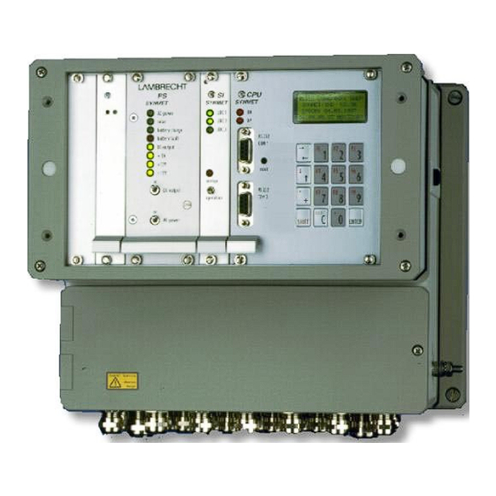
7.0 Setting to work 7.1. Field-test of the system Check all electrical connections thorougly (according to the LAMBRECHT wiring diagram) before connecting the mains. The two switches on the Power Supply Module PS ("AC-power" and "DC-power") both have to be in the "on"-position. - Page 12 Figure: Front panel SYNMET Figure: circuit diagram of data cable (connection of Sub-D-connectors) X:\PmDoku\Geräte\Synmet NAV\englisch\SYNMET MANUALE 1.doc STW Manual Page 12 of 25...
-
Page 13: Data-Transmission Test
"FT 50 LITE" in the same way as written above. 8.0 FT 50 LITE To test a SYNMET-system by its serial interface, install the LAMBRECHT test- and configuration-software "FT 50 LITE" according to the instructions of the manual "FT 50 LITE" on a computer. The software guides the user through self-explaining menus. - Page 14 Details regarding the installation and the setting to work (initial operation) of these phone-modems are described in separate manuals. In most countries, LAMBRECHT delivers tested and approved modems together with the system. Due to different local telecommunication regulations in some countries, modems could require an approval of the local authorities (in these cases they have to be purchased locally).
-
Page 15: Network Solutions
In some of these cases LAMBRECHT may have got an order for the assistance during the setting into operation procedure of complex network systems. When carrying these works by our company the following requirements have to be secured by the buyer: •... -
Page 16: Keyboard And Display Unit
10.3. Keyboard and display unit 10.3.1. General With the keyboard and display unit it is possible to check the function of SYNMET without further devices. The following functions are available: • Manuel or automatic display of the instantaneous measuring values •... - Page 17 Function menu In the function menu the desired function will be select by the displayed function key. Function key Function Go to the submenu Displaying values Set the SYNMET clock Select the display Choice the language Exit Exit this menu Submenu Displaying values Function key Function...
-
Page 18: Pressure-Sensor And Uninterruptable Power-Supply Unit
10.4. Pressure-sensor and Uninterruptable power-supply unit 10.4.1. General remarks The barometer and accumulator module is designed as a printed circuit board with a 4 units front panel carrying the options barometer and buffer accumulator which can be integrated into a slot of the SYNMET housing as a compact solution. -
Page 19: Interface Design Specifications
11.0 Interface design specifications 11.1. The LAMBRECHT standard message format With this description you shall be provided to develop your own device driver for the communication with the FMA 186 / SYNMET up the firmware 3.0. With a sequence of commands (ASCII - characters) different processes will carried out at SYNMET. -
Page 20: Meteorological Message-Formats
• SYNOP (synoptic observations) • SPECI (special weather messages) 12.1. NMEA 0183 message-format Especially for maritime applications (apart from the LAMBRECHT-standard message format) the system can generate standardized messages from the following meteorological parameters: wind speed wind direction air temperature... -
Page 21: Trouble-Shooting
In case of problems, we kindly ask the user to study all provided literature thouroughly before calling our service staff. When contacting our service staff by phone, facsimile or e-mail, make sure to have all specific information at hand. Wilh. LAMBRECHT GmbH Mailing address: Friedlander Weg 65/67... -
Page 22: Components And Technical Data Of The Synmet-System
14.0 Components and technical data of the SYNMET-system CPU Board The main element of the system is a powerful NEC V25 microprocessor. This processor uses a well tried firmware written in the Turbo Pascal high-level language. Maintenance and adjustment of the firmware to future requirements can be performed quickly and therefore in a cost-efficient way. - Page 23 Electrically isolated DAC extension Extension by keyboard and CPU board as described above, but additionally measured value display with: CPU board as described above, but additionally 8 analog outputs, short circuit-proof with: Accuracy: ±0.05% extended numeric keypad and Current: 0(4)...20 mA multiple line LCD display Voltage: 0...10 V...
- Page 24 Power Supply Sensor Input Board SI Several different power supply modules are available to The sensor input board comprises voltage divider and support a variety of applications. adjustment modules and thus provides the technical Standard power supply module adjustment of the sensor input signals. Input range: 90...260 V AC SI Quick Info Power:...
-
Page 25: Maintenance
"FT 50 LITE". The detailed use of it is described in a separate manual. 17.0 Further technical manuals As mentioned before, further manuals and literature is available from Lambrecht and is delivered together with the goods: •...
Need help?
Do you have a question about the SYNMET-IND Series and is the answer not in the manual?
Questions and answers