Table of Contents
Advertisement
Quick Links
Advertisement
Table of Contents

Related Manuals for L-Acoustics LS10

Summary of Contents for L-Acoustics LS10
- Page 1 LS10 owner's manual (EN)
- Page 2 Document reference: LS10 owner's manual (EN) version 1.0 Distribution date: April 8, 2020 © 2020 L-Acoustics. All rights reserved. No part of this publication may be reproduced or transmitted in any form or by any means without the express written consent of the publisher.
-
Page 3: Table Of Contents
Contents Safety................................5 Important safety instructions........................5 Symbols..............................6 Introduction................................ 7 How to use this manual..........................7 LS10 AVB switch............................8 System components.............................9 Cables..............................9 Rigging elements............................9 Technical description............................10 Main features............................10 Components..........................10 Front and rear panels........................11 Ethernet ports............................11 Power supply............................11... - Page 4 Operation................................ 24 LS10 LED colors............................24 Reset button............................24 Using Switch Conguration Tool....................... 25 Introduction...........................25 Assigning individual IP addresses to the LS10 of a network............... 26 Updating the LS10 rmware......................30 Ethernet............................32 USB............................. 35 Specications..............................36 Appendix................................. 39 Appendix A: Glossary..........................39...
-
Page 5: Safety
This system is intended for use by trained personnel for professional applications. As part of a continuous evolution of techniques and standards, L-Acoustics reserves the right to change the specications of its products and the content of its documents without prior notice. -
Page 6: Symbols
This symbol noties the user about complementary information or optional instructions. Do not open unless authorized. This symbol indicates the presence of electrical shock hazards. It also indicates that no maintenance performed by the end user requires access to internal components. LS10 owner's manual (EN) version 1.0... -
Page 7: Introduction
Introduction How to use this manual The LS10 owner's manual is intended for all actors involved in the system design, implementation, preventive and corrective maintenance of the LS10 product. It must be used as follows: 1. Read the technical description for an overview of all product elements, their features, and their compatibilities. -
Page 8: Ls10 Avb Switch
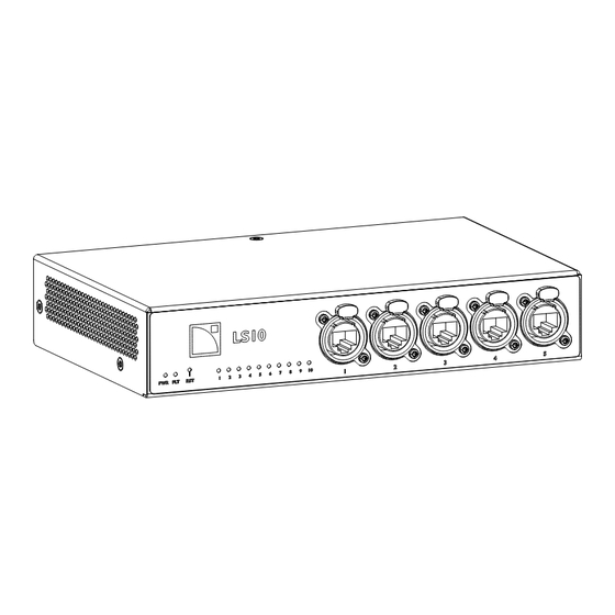
™ On its own or as an integral part of the LA-RAK II AVB, LS10 distributes audio and control via front and rear etherCON connectors and SFP cages, enabling long-distance optical links. Two units mounted side-by-side on the dedicated 1U rack shelf allow to create a seamless redundant network effortlessly. -
Page 9: System Components
1U Rack shelf for two LS10 Rack LA-RAK II AVB Touring rack containing three LA12X, LA-POWER II for power distribution, LA- PANEL II for audio and network distribution, and two LS10 for AVB distribution Software applications Switch Conguration Tool Application for remote monitoring of LS10 Cables ™... -
Page 10: Technical Description
• 1 6-point terminal block that gathers: • 1 24 V DC IN / 1 24 V DC OUT pin for power supply backup • GPO for status control • 1 USB port for maintenance and switch conguration LS10 owner's manual (EN) version 1.0... -
Page 11: Front And Rear Panels
AVB streams regardless of the number of channels of these streams. Power supply LS10 relies on a universal Switched Mode Power Supply (SMPS) suitable for mains from 100 V AC to 240 V AC (± 10%), 50 Hz to 60 Hz. -
Page 12: Inspection And Preventive Maintenance
CHK - External structure icon indicates a visual inspection. chassis is not damaged front and rear connectors are not damaged CHK - External cleanness Use a dry cloth to remove any dust from the side grills. LS10 owner's manual (EN) version 1.0... -
Page 13: Chk - Network Functionalities And Rmware
Using Switch Conguration Tool (p.25) for more information. 4. Check that all L-Acoustics switches in the system run the same version of the rmware. 5. If convenient, update LA Network Manager and the rmware to the latest version. LS10 owner's manual (EN) version 1.0... -
Page 14: Installation
Mounting LS10 is one rack unit high (1U) and a half rack unit wide. LS10-RAKSHELF is a rigging accessory that can contain up to two LS10 side by side. LS10-RAKSHELF is mounted to LA-RAK II AVB and can be mounted to LA-RAK II as well as other 19-inch racks. - Page 15 Installation 2. Place the screws in the appropriate holes. 3. Tighten the screws. 1 N.m 4. Turn back the assembly to nominal position for cabling and mounting. LS10 owner's manual (EN) version 1.0...
-
Page 16: Ventilation
When rack-mounted, make sure airow is not reduced. General Purpose Output (GPO) LS10 features a 6-point terminal block on the rear panel that includes a congurable GPO to indicate the presence of a fault on the LS10. It can be connected with a 6-point terminal block. -
Page 17: 24 V Dc Input And Output
It is also possible to power LS10 with an external power supply. Backup power cable In case of component fault inside one LS10, the other LS10 will automatically provide backup power thanks to this cable. To do so, each LS10 must be connected to independent power sources. - Page 18 Installation External 24 V DC powering 24 V DC ± 10% 10 W 24 V DC IN = PIN 5 External power supply GND = PIN 2 LS10 owner's manual (EN) version 1.0...
-
Page 19: Network Cabling
LS10 can work with OM3 ber optic cables with 1000BASE-SX SFP modules (LC connector, 850 nm). The maximum link length is 550 m. The ber bending radius (maximum bending capacity) depends on the cable manufacturer recommendation. -
Page 20: Cabling Examples
Installation Cabling examples Example of non-redundant network with hybrid topology LA12X LA4X LA4X LS10 front Ethernet Ethernet AVB rear Console Computer LS10 owner's manual (EN) version 1.0... - Page 21 Installation Example of redundancy topology front front LS10 LS10 rear rear rear front primary network secondary network Computer LS10 owner's manual (EN) version 1.0...
-
Page 22: Connecting To Ac Mains
Only connect the product to an AC power outlet rated 100-240 V, 50-60 Hz. The product draws 10 W (typical). The product draws 20 W (typical) when it powers another LS10. WARNING: The product is of CLASS 1 construction and shall be connected to a mains socket outlet with a protective connection to earth. -
Page 23: Power Consumption
Installation Power consumption LS10 power requirement is 10 W. For an LS10 that powers another LS10 via 24 V DC, it is 20 W. Powering on/off LS10 features one power LED indicator. To power LS10 on, connect the IEC cable. LS10 is detected and operational in less than 5 seconds. -
Page 24: Operation
Reset button It is possible to reset LS10 to factory default settings using the Reset button. Press the RST button and hold it for seven seconds to set back the switch to factory default settings. It sets back: •... -
Page 25: Using Switch ConGuration Tool
Using Switch Conguration Tool Introduction LS10 can be remotely congured using the Switch Conguration Tool application. The application is available from the main menu of LA Network Manager version 3.1.0 minimum. The Switch Conguration Tool allows to congure the connected LS10 with the following parameters: •... -
Page 26: Assigning Individual Ip Addresses To The Ls10 Of A Network
4. Select the NIC. 5. Click Scan. The default IP address of LS10 is 192.168.1.200. If the switch is not detected, then press the RST button of the switch for seven seconds to reset the IP address, and scan again. - Page 27 10. Repeat the above procedure until all LS10 are congured. What to do next After all LS10 are set to a unique IP address, it becomes possible to interconnect them and modify their settings or proceed to their rmware update from the Switch Conguration Tool.
- Page 28 If the IP addresses of the switches need to be set on a different subnet, then proceed as follows. Basic use only The USB tab is used to display and change the IP settings of LS10. Connect the switch with an Ethernet cable and use the Ethernet tab for a complete conguration.
- Page 29 10. Click Apply. What to do next After all LS10 are set to a unique IP address, it becomes possible to interconnect them and modify their settings or proceed to their rmware update via Ethernet from the Switch Conguration Tool.
-
Page 30: Updating The Ls10 Rmware
Operation Updating the LS10 rmware The Switch Conguration Tool is the only way to update the rmware of LS10. The Units that are connected to the switch are unavailable during the rmware update. Procedure 1. Set the NIC of the computer hosting LA Network Manager to 192.168.1.254 / 255.255.255.0. - Page 31 The LS10 will automatically reboot and install the new rmware. What to do next Wait for 20 seconds, then click Scan again to detect LS10. Select the switch to read its rmware version on the right and verify that the installation succeeded.
-
Page 32: Ethernet
LS10 match. the network card and the LS10 pertain to the same subnet. 2. Update rmware: allows to update the rmware of one more LS10 that have been detected, after selecting them in the central frame. - Page 33 GPO options. IP settings It is possible to change the IP settings (address, netmask, gateway). After changing the IP address, the LS10 will be disconnected. Go to the Network tab to retrieve the switch. LS10 owner's manual (EN) version 1.0...
- Page 34 FLT (Fault) LED may blink. In this case, it is necessary to reset internal components in order to recover from the optical port incident. The Error Auto Recovery enables the automatic reset of LS10 in case of optical link disconnection. It takes a few ms to apply.
-
Page 35: Usb
When it is not possible to connect the device with Ethernet connectors, it is possible to at least identify the device connected to the USB port. It is also possible to set the IP address with the USB tab. Refer to Setting the IP via USB (p.28) for more information. LS10 owner's manual (EN) version 1.0... -
Page 36: SpeciCations
Terminal block connector 5 mm 6-point terminal block connector for GPO and DC powering with: • 1 × 24 V DC power output (max 10 W) to power another LS10 • 1 × 24 V DC backup power input (max 10 W) •... - Page 37 Height × Width 1.7 in × 8.5 in (1U × 1/2U) Weight 1 kg / 2.2 lb Finish black Protection rating IP3x LS10 dimensions 216 mm / 8.5 in 42 mm / 1.7 in LS10 owner's manual (EN) version 1.0...
- Page 38 Specications LS10-RAKSHELF specications Description 1U Rack shelf for two LS10 6 × M3×6 Torx screws Weight (net) 1.1 kg / 2.4 lb Material electrogalvanized steel LS10-RAKSHELF dimensions 483 mm / 19 in 465 mm / 18.3 in 31.8 mm / 1.2 in 44 mm / 1.7 in...
-
Page 39: Appendix
Appendix Appendix Glossary Europe check procedure China disassembly/reassembly procedure Japan repair kit SMPS Switched Mode Power Supply (power supply inside of the amplied controller) United States LS10 owner's manual (EN) version 1.0... -
Page 40: Appendix B: Approvals
Appendix Approvals LS10 is compliant with the following: Avnu Alliance and the Avnu design mark are registered trademarks and/or service marks of Avnu Alliance. LS10 owner's manual (EN) version 1.0... - Page 41 L-Acoustics 13 rue Levacher Cintrat - 91460 Marcoussis - France +33 1 69 63 69 63 - info@l-acoustics.com www.l-acoustics.com...
Need help?
Do you have a question about the LS10 and is the answer not in the manual?
Questions and answers