
Subscribe to Our Youtube Channel
Related Manuals for Areva HVX Series

Summary of Contents for Areva HVX Series
- Page 1 MEDIUM VOLTAGE SWITCHING DEVICE Vacuum circuit-breaker ≤ 17,5 kV (> 2500 A / ≤ 50 kA) Installation Operation Maintenance No. AGS 531 461-01 Edition 06/07 Technical instruction AREVA T&D...
- Page 2 All rights reserved to this technical instruction. Reproduction and making available of this technical instruction, or extracts, to third parties are prohibited. Only integral reproduction of this technical instruction is permitted with the written permission from AREVA Energietechnik GmbH, Sachsenwerk Medium Voltage.
-
Page 3: Table Of Contents
Content Regulations and Provisions Remarks on this Technical Instruction Terms and symbols used Use in line with the intended purpose Applied standards Safety provisions Disposal after the end of service life Variants Technical data Type designation Technical data Control and operating devices Shipping instructions Packaging Delivery... -
Page 4: Regulations And Provisions
1 Regulations and Provisions 1.1 Remarks on 1.2 Terms and 1.3 Use in line with the this Technical symbols used intended purpose Instruction This Technical Instruction uses cer- The HVX vacuum circuit-breaker is This Technical Instruction describes tain terms and symbols. They warn intended exclusively as a switching transport, assembly, operation, hand- about dangers or provide important... -
Page 5: Applied Standards
1.4 Applied 1.5 Safety provisions 1.6 Disposal after the standards end of service life The work described in this Technical The three-pole HVX vacuum circuit- A manual on disposal after the end Instruction may only be performed by breaker of the service life is available for dis- specialist electricians who have pro- posal of the HVX vacuum circuit ved their experience with the HVX... -
Page 6: Variants
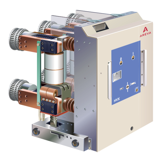
2 Variants Fig. 2.1 Vacuum circuit breaker HVX-F – fixed type 64-pole low-voltage terminal 10 Insertion opening for manual char- ging of the closing spring Information plate for commissioning 11 Operation counter User interface 12 Press rod (transfer of ON/OFF swit- Switch circuit-breaker ON ching movement) Switch circuit-breaker OFF... - Page 7 Fig. 2.2 Vacuum circuit breaker HVX-E with withdrawable part for PIX switchgear panels Low-voltage terminal Information plate for commissioning User interface Position indicator - withdrawable part in service position Position indicator - withdrawable part in disconnected position Lever for locking/unlocking the with- drawable part in the panel Insertion opening for manual racking in/out the withdrawable part...
-
Page 8: Technical Data
3 Technical data 3.1 Type designation Example 12 - 50 - 12 - E The type designation on the name- Series HVX plate (Fig. 2.1) specifies essential technical data. The type designation Rated voltage 12 kV (1) is broken down in this example. Rated short-circuit breaking current 50 kA Rated normal current 1250 A F: fixed type... -
Page 9: Control And Operating Devices
3.3 Control and operating devices The circuit breaker has been desi- Overview of rated supply voltages gned on principle so as to permit Direct voltage DC manual operation. Alternating voltage AC [V] (110) / 120 (220) / 230 The drive mechanisms of the indivi- dual switching devices can be equipped, depending on the specific Power consumption, solenoids and motor... - Page 10 Auxiliary switch Technical data of auxiliary switches for circuit-breaker (3 x 8-pole) Auxiliary switches are always actua- Rated ted directly by the switch shaft via an supply voltage intermediate linkage. Their position <48 always corresponds to that of the Switching capacity main contacts.
-
Page 11: Shipping Instructions
4 Shipping instructions 4.1 Packaging 4.4 Transport • As standard, the switching devi- Transport using a forklift truck: Type HVX Weight [kg] ces are packed in cardboard bo- Only transport the circuit-breaker on xes and fastened on a pallet by fixed type a pallet. -
Page 12: Assembly
5 Assembly 5.1 Instructions for assembly Warning! Observe the safety pro- • Dimension drawings are made The vacuum circuit-breakers HVX-F visions of chapter 1.5. available on request. and HVX-E are delivered in comple- Warning! tely assembled and ready-to-operate • Check technical data on name- Risk of injuries. - Page 13 Connecting conductor bars Important: Aluminium conductor bars must not be connected to M 12 silver-plated connection Thread reach Einschraub- 15 – 22 mm areas of the circuit-breaker. Inadmis- tiefe 15-22 mm sible matching of materials. Important: Coat contact surfaces and comply with the specified tightening torques (refer to Annex).
-
Page 14: Hvx-E - Mechanical Assembly
5.3 HVX-E – Mechanical assembly A transport truck (optional) is used to rack the circuit-breaker into the switchgear panel (Fig. 5.6). For the design and method of operation of the transport truck used, please refer to the instructions for the panel in question. -
Page 15: Connecting The Control Lines
Earth terminal 5.4 Connecting the control lines The switching device potential is lin- The control lines are connected, de- ked to the panel via the four wheels pending on design, via control con- of the withdrawable part (Fig. 5.6). nectors (Fig. 5.9 and 5.10) or con- trol lines to the terminal strips in the drive casing. -
Page 16: Commissioning
6 Commissioning • Check circuit-breaker for external Remove transport protection damage. Important: 1. Remove front cover. • Make sure that there are no ex- Observe the warning and 2. Remove transport securing devi- ternal parts in the circuit-breaker notification plates on the ce (red) by releasing the thread- compartment. -
Page 17: Hvx-E (Withdrawable Unit)
6.1 HVX-E 6.2 HVX-F (withdrawable unit) (fixed type) Perform functional tests: Check assembly work: 1. Charge energy-storing device – Check securing bolts. using the crank. Check the spring – Check the conductor bars' position indicator. screw couplings using a tor- 2. -
Page 18: Operation
7 Operation 7.1 Control elements and operator interface button (rocker “O”) or pushbutton “O” to switch circuit breaker OFF (open) button (rocker “I”) or pushbutton “I” to switch circuit breaker ON (close) Nameplate Sachsenwerk Type HVX 24 -16 -00 -21 Operation counter NO SW1 3340121001 1999... -
Page 19: Interlocks
7.2 Interlocks Warning! Mechanical interlocks Electrical interlocks You must be familiar The HVX switch features basic inter- have been designed according to with these interlocks locks to prevent operating errors. the circuit diagram. before operating the circuit-breaker. Interlock Function of interlock Method of operation of interlock Switch cannot be moved into service position un- The opening for the moving crank... -
Page 20: Switching The Circuit Breaker
7.4 Switching the circuit breaker Closing (ON) Opening (OFF) • Push button "ON" (I) or • Push button "OFF" (O) or • actuate closing release electrical- • actuate via opening release or • by undervoltage release or se- The position indicator shows the condary release switch position "ON"... -
Page 21: Actuate Withdrawable Part
7.5 Actuate withdrawable part Important: Observe interlock conditi- ons (see chapter 7.2). 7.5.1 Withdrawable part for PIX 7.5.2 Withdrawable part for PIX high current switchgear panels switchgear panels Move circuit-breaker from Move circuit-breaker from Move circuit-breaker from disconnected into service service into disconnected disconnected into service position by hand:... -
Page 22: Servicing
8 Servicing 8.1 Safety 8.2 Servicing schedule Series HVX vacuum circuit-breakers Only specialist electricians certified 1. On principle, the 5 safety rules require regular inspections. The in- by the manufacturer for maintenance applicable for electrical enginee- tervals depend on the strain to which work regarding series HVX vacuum ring must be complied with befo- the switches are subject during ope-... -
Page 23: Cleaning Insulating Components
8.3 Cleaning insulating 8.4 Corrosion 8.5 Avoid components protection condensation To ensure the specified insulating le- Drive mechanisms and covers have a To ensure the specified insulating le- vel, the insulating components must long-term protection against corrosi- vel, the circuit-breaker - especially its be clean. -
Page 24: Lubrication Instructions
8.6 Lubrication instructions Warning! Important: Important: Comply with safety pro- Only approved lubricants The following elements visions (Chapter 1.5). may be used (section 9.2). must not be lubricated: Preparation - Motor Warning! - Electric releases Remove the withdrawable part from Risk of injury: - Push switches the switchgear cubicle for inspection... - Page 25 Withdrawable part in PIX switchgear panels • Spindle of withdrawable part me- chanism (Fig. 8.2, item 1). The spindle is accessible from below • Geared wheels of withdrawable part mechanism (only in case of motor-drive (Fig. 8.2, item 2)). The geared wheels are accessi- ble once the lower front cover has been removed.
- Page 26 Moving contacts The lubrication procedure is descri- bed in the table on page 24. Fig. 8.4 Moving contacts Contact lubricant Kontasynth Final steps Remove transport securing device in the drive. Re-mount the cover plate and insert the circuit-breaker in the panel (see section 5).
-
Page 27: Maximum Admissible Number Of Breaking Operations Of The Vacuum Chambers
8.7 Maximum admissible number of breaking operations of the vacuum chambers The diagram defines exclusively the Rated (normal) current I 1250 A, 2500 A, 3150 A Bemessungs-Betriebsstrom I 1250 A, 2500 A, 3150 A maximum admissible numbers of 30 000 breaking operations of the circuit- breaker as a function of the rated 10 000... -
Page 28: Annex
9 Annex 9.1 Accessories Fig. 9.1 Accessories for HVX circuit-breaker Position Designation Order no. ON/OFF operating rod AGS H35 446-01 Spring charging crank for spring operating mechanism AGS H30 498-01 AGS H31 642-01 Moving crank handle with integrated slip coupling for withdrawable parts in PIX AGS H32 532-01 switchgear panels AGS H31 674-01... -
Page 29: Screw Fastenings
9.3 Screw fastenings The following elements must be Thread Tightening torque Thread Tightening torque used for all metal screw couplings: size [Nm] size [Nm] • Screws and bolts: min. max. min. max. Grade ≥ 8.8 • Nuts: Grade 8. Table 2: Screw coupling between switching Table 1: device and conductor bar with cop-... - Page 30 Notes:...
- Page 32 AREVA T&D Worldwide Contact Centre http://www.areva-td.com/contactcentre/ +44 (0) 1785 250 070...
Need help?
Do you have a question about the HVX Series and is the answer not in the manual?
Questions and answers