
Summary of Contents for IPG Photonics YLR Series
- Page 1 HP Switch Software Management and Configuration Guide and Configuration Guide YLR-Series User Guide Part Number: P21-010106, YLR-Series SLED 3.0 Published: April 2015 Revision: B DCO: 956...
- Page 2 Disclaimer Notice US Export Control Compliance (for US products only) © IPG Photonics Corporation 2015. All rights reserved. You IPG is committed to complying with U.S. and foreign export, may not copy, reproduce, transmit, store in a retrieval import and customs requirements. Export and re-export of...
- Page 3 Preface Ensure you read and understand this guide in its entirety and familiarize yourself with the operating and maintenance instructions before you use the product. IPG strongly recommends that all operators of the product read and pay particular attention to all safety information contained herein prior to operating the product.
- Page 4 Preface Audience...
-
Page 5: Table Of Contents
Contents Preface Audience ..........i-i 1 Overview of the YLR-Series Fiber Lasers Introduction . - Page 6 Certification ..........2-3 YLR Series — Front Panel View ......2-3 YLR Series —...
- Page 7 3 Computer Interface/Commands RS-232 Configuration ........3-1 Ethernet TCP/IP Interface .
- Page 8 Creating a New Pulse Sequence ......4-38 Building a Sequence ........4-39 Modifying a Pulse Sequence .
- Page 9 D Warranty Limited Express Product Warranties ......D-1 Warranty Limitations ........D-1 Limitation of Remedies and Liabilities .
- Page 10 viii...
-
Page 11: Audience
Overview of the YLR-Series Fiber Lasers Introduction The IPG Photonics YLR-Series fiber lasers are developed to meet industrial market demands of efficient reliable maintenance-free high power lasers. These lasers are a diode-pumped Ytterbium fiber laser with output powers ranging from 1W up to 1.5 kW operating at the wavelength region of 1060 - 1100 nm. -
Page 12: Safety Information And Conventions
Overview of the YLR-Series Fiber Lasers Safety Information and Conventions Safety Information and Conventions To ensure the safe operation and optimal performance of the product, follow all warnings in this guide. Safety precautions must be observed during all phases of operation, maintenance, and service. -
Page 13: Safety Features And Compliance To Government Requirements
Overview of the YLR-Series Fiber Lasers Safety Features and Compliance to Government Requirements Safety Features and Compliance to Government Requirements Compliance to Regulatory Standards (on applicable units) EMC Emissions: EN 55011:2009 + A1:2010 CISPR 11:2009 + A1:2010 FCC Class A EMC Immunity: EN 61000-3-2:2006+A1:2009+A2:2009 EN 61000-3-3:2008... -
Page 14: Class A Digital Device
Overview of the YLR-Series Fiber Lasers Safety Features and Compliance to Government Requirements Functional Safety: The following safety functions are implemented to fulfill the requirements of EN ISO 13849-1:2008 + A1:2009 Cat.3 / PL d and Category 3 (Cat. 3). The safety functions are implemented exclusively in hardware: •... -
Page 15: Laser Classification
Overview of the YLR-Series Fiber Lasers Safety Features and Compliance to Government Requirements The European requirements for Electromagnetic Compliance are specified in the “EMC Directive.” Conformance to the “EMC Directive” is achieved through compliance with the harmonized standards EN55011 for emission and EN 61326- 1:2006 for immunity. -
Page 16: Safety Label Locations
Safety Label Locations The YLR Series Laser has the required laser safety labels located on the outside of the chassis in various locations. These include warning labels indicating removable or displaceable of the protective housings, apertures through which laser radiation is emitted and labels of certification and identification. - Page 17 Overview of the YLR-Series Fiber Lasers Safety Features and Compliance to Government Requirements Figure 1-1. Safety Label Locations - WC YLR-Series Laser Figure 1-2. Safety Label Locations - AC YLR-Series Laser...
- Page 18 Overview of the YLR-Series Fiber Lasers Safety Features and Compliance to Government Requirements Table 1-2. Safety Label Descriptions Item Label Name Description Aperture Label FDA Compliance (for US Products) Class 2M Laser Product Label for Guide Laser...
- Page 19 Overview of the YLR-Series Fiber Lasers Safety Features and Compliance to Government Requirements Class 4 Laser Product (Models: YLR-10, YLR-15, YLR-20, YLR-25, YLR-30) Class 4 Laser Product (Models: YLR-40, YLR-50, YLR-60 to YLR-70) Class 4 Laser Product (Models: YLR-75, YLR-100, YLR- 150)
- Page 20 Overview of the YLR-Series Fiber Lasers Safety Features and Compliance to Government Requirements Class 4 Laser Product (Models: YLR-200, YLR-250, YLR- 300, YLR-350) Class 4 Laser Product (Models: YLR-400, YLR-500, YLR- 600, YLR-700) 4. Class 4 Laser Product (Models: YLR-750, YLR-800, YLR- 900, YLR-1000) 1-10...
- Page 21 Overview of the YLR-Series Fiber Lasers Safety Features and Compliance to Government Requirements Class 4 Laser Product (Models: QCW YLR-150/1500) 4. Class 4 Laser Product (Models: QCW YLR-300/3000) Identification Plate (Products Made in the United States) 1-11...
- Page 22 Overview of the YLR-Series Fiber Lasers Safety Features and Compliance to Government Requirements Identification Plate (Products Made in Germany) Laser Radiation Hazard Label Protective Conductor Terminal Electrical Hazard Label CE Compliance 1-12...
-
Page 23: Emission-On Indicator
Overview of the YLR-Series Fiber Lasers Safety Features and Compliance to Government Requirements Fuse Refer to Table 2-1 on page 2-2 for Model Designation Codes. Refer to Table 2-1 on page 2-2 for Model Designation Codes. This symbol is specifically reserved for the PROTECTIVE CONDUCTOR TERMINAL and no other. -
Page 24: General Safety Instructions
Overview of the YLR-Series Fiber Lasers General Safety Instructions General Safety Instructions WARNING: You must exercise caution to avoid and minimize specular reflections as these reflections occur at the laser's wavelength and are invisible. Specular Reflections Often there can be numerous secondary laser beams produced at various angles near the laser aperture. -
Page 25: Optical Safety
Overview of the YLR-Series Fiber Lasers General Safety Instructions • Use the laser in a room with access controlled by door interlocks. Post warning signs. Limit access to the area to individuals who are trained in laser safety while operating the laser. -
Page 26: Environmental Safety
Overview of the YLR-Series Fiber Lasers General Safety Instructions 3. For continued protection against fire hazard, replace the line fuses (if applicable) with only the same types and ratings. The use of other fuses or material is prohibited. 4. Before supplying the power to the instrument, ensure that the correct voltage of the AC power source is used. - Page 27 Overview of the YLR-Series Fiber Lasers General Safety Instructions CAUTION: Damage to the laser is possible, unless caution is employed in operating the device. IPG provides the following recommendations to promote the long life of the IPG laser: • Do not expose the device to a high moisture environment (>95% humidity). CAUTION: Water-cooled lasers must not operate at temperatures below the respective ambient dewpoint (see Table 1-3 on page 1-17).
- Page 28 Overview of the YLR-Series Fiber Lasers General Safety Instructions These values are calculated using the August-Roche-Magnus approximation. 1-18...
-
Page 29: Additional Safety Resources
Laser Safety Equipment Laurin Publishing Laser safety equipment and Buyer's Guides IPG Photonics recommends that the user of this product investigate any local, state N o t e or country requirements as well as facility or building requirements that might apply to installing or using a laser or laser device. - Page 30 Overview of the YLR-Series Fiber Lasers Additional Safety Resources 1-20...
-
Page 31: Using Your Device
Using Your Device Overview The IPG Photonics YLR-Series fiber lasers are developed for use in industrial applications. The lasers are compact and efficient letting you replace bulky and less efficient lasers. Main application are welding, cutting, and brazing. Main Features •... - Page 32 Additional Information WC — Water Cooled device AC — Air Cooled device Additional Information The last two digits of the model year, Table 2-2. Available YLR Series Models Category Model 3U-AC YLR-20, YLR-30, YLR-50, and YLR-100-AC 3U-WC YLR-100-WC, YLR-200-WC, YLR-300-WC, YLR-400-WC, YLR-500-WC, YLR-600-WC,...
-
Page 33: Certification
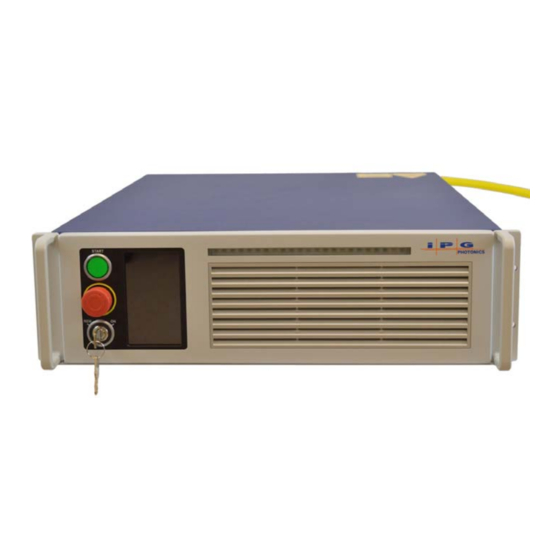
Certification Certification IPG Photonics certifies that your system is thoroughly tested and inspected and meets published specifications prior to shipping. Upon receiving your device, check the packaging and parts for any possible damage that might have occurred in transit. If there is damage, contact IPG Photonics immediately. - Page 34 Using Your Device YLR Series — Front Panel View Table 2-3. Front Panel Descriptions Item Feature Description Keyswitch The 3-position key switch controls the laser operation mode: (Local Interface option only) Left position — Chassis Powered On, Remote Control Mode Central position —...
- Page 35 Using Your Device YLR Series — Front Panel View Figure 2-3. Front Panel View without Display Figure 2-4. Front Panel Descriptions Item Feature Description Power When lit, indicates that internal main power supply of the laser is on. When the indicator is on, the internal power supply is active and the laser is capable of producing laser radiation.
-
Page 36: Ylr Series - Rear Panel View
Using Your Device YLR Series — Rear Panel View YLR Series — Rear Panel View The YLR-Series is available as a Water-Cooled (WC) or Air-Cooled (AC) laser. Figure 2-5 shows details of the rear panel of the YLR-Series WC laser. Table 2-4 lists details for each component. - Page 37 Using Your Device YLR Series — Rear Panel View Item Feature Description AC line input The 3-pin screw terminal connector for AC input wiring. Refer to the SPECIFICATION YTTERBIUM FIBER LASER document included with this product to determine your models power requirement.
- Page 38 Using Your Device YLR Series — Rear Panel View Figure 2-6. Rear Panel View - AC Laser Table 2-5. Rear Panel Descriptions Item Feature Description Laser Output The output of the laser (fiber cable) is delivered through this location. Hardwiring Interface (7-pin) The 7-pin connector provides status of the power supply and front panel Emergency Stop (if present).
-
Page 39: Optical Output Fiber Terminations
Using Your Device Optical Output Fiber Terminations Optical Output Fiber Terminations Products with a Connector The end connector of the fiber (as shown in Figure 2-7) uses a protective cap that covers and protects the optical surface and electrical contacts when not in use. These protective caps must be removed from the connectors when connecting the process fiber cable of the laser to an appropriate optical interface. -
Page 40: Products With A Collimator
Using Your Device Model Specifications Products with a Collimator Collimators have a protective window that can be replaced if damaged (as shown in Figure 2-8). You must remove the collimator end cap prior to use. This cap can be re-used when storing the system. Cleaning of the protective window should be performed as needed using the same materials and techniques described in “Optical Fiber Connector Inspection and Cleaning”... -
Page 41: Unpacking Instructions
Laser models that are larger and relatively heavy are packaged in foam insulated wooden crates. See “Unpacking a Unit from a Wooden Crates” on page 2-14. To minimize the risk of damage to your system, IPG Photonics recommends that you unpack your laser using the following procedures. - Page 42 Using Your Device Unpacking Instructions 6. Check the inventory of following items: Shipping Box Contents Quantity Cover, AC Power Inlet (P45-001394) Strain Relief (P40-002294) Strain Relief Nut (P40-002293) Harting 24-pin Interface Connector Kit (P30-007268) Connector (P40-001344) Hood (P40-001343) Cable Seal (P40-000891) Contact Pins (P40-000888) Contact Pins (P40-000887) Keys...
- Page 43 Using Your Device Unpacking Instructions Figure 2-9. Unpacking a Unit from a Cardboard Box 2-13...
-
Page 44: Unpacking A Unit From A Wooden Crates
Using Your Device Unpacking Instructions Unpacking a Unit from a Wooden Crates See Figure 2-10 on page 2-15 for an illustration of this procedure. To unpack a unit from a wooden crate: 1. Place the package on a stable surface such as the floor or a large table. IPG recommends using a powered screwdriver to remove all of the top screws securing the top lid. - Page 45 Using Your Device Unpacking Instructions Figure 2-10. Unpacking a Unit from a Wooden Crate 2-15...
-
Page 46: Using The Ylr-Series
Using Your Device Using the YLR-Series Using the YLR-Series CAUTION: Refer to the SPECIFICATION YTTERBIUM FIBER LASER document included with this product for proper electrical power requirements. Before switching the power on, ensure that the incoming AC voltage is equal to the level noted in the specification. -
Page 47: Interface Wire Specification
Using Your Device Using the YLR-Series Figure 2-11. Power Cord Connection Interface Wire Specification The minimum wire gage is 18AWG at 15 meters (30 meters maximum regardless of gauge). The gage of the wire must increase as the distance increases. For connectivity, the wiring and/or cabling must have an overall shield to ensure proper functionality. -
Page 48: Interlock Safety Circuit
Using Your Device Using the YLR-Series Interlock Safety Circuit YLR lasers include an Interlock Safety Circuit that uses a dual-channel system with monitored output and manual reset. When you open the Interlock, the safety circuit opens and power to the laser diodes is removed. -
Page 49: Interface Connector Pin Assignments
Using Your Device Using the YLR-Series Interface Connector Pin Assignments Table 2-6 provides electrical pin assignments for these Interlock Channels. Table 2-6. 24-Pin Connector Pinouts Pin Signal Name Signal Type Signal Signal Typical Description Level Drive Response Time Interlock Ch1A Contact Closure <... - Page 50 Using Your Device Using the YLR-Series Table 2-6. 24-Pin Connector Pinouts Emission Enable Digital Input 5 to 6 mA 120ms Positive edge activates emission in Remote Control 24 VDC (sink) Mode. Error/Ready Digital Output 24 VDC 100 mA 120 ms Low indicates a laser error.
- Page 51 Using Your Device Using the YLR-Series Table 2-7. 24-Pin Connector — Additional Details Signal Name Description Interlock Ch1A These connections are intended to satisfy the Remote Interlock Connector requirement as defined by 21 CFR 1040.10 (f)(3) and IEC 60825-1 (4.4). If the Interlock Ch2A connections between pins 1-4 or 2-3 are breeched by a door interlock or other means, laser emission is prevented.
- Page 52 Using Your Device Using the YLR-Series Signal Name Description Emission Enable Intended to control the level of laser output power with Remote Control Mode enabled, power supply enabled, and external emission control enabled. The emission enable signal is not intended to be used for functional safety or as a safety device.
- Page 53 Using Your Device Using the YLR-Series Table 2-8. 7-Pin Connector Pinouts Signal Name Signal Signal Signal Typical Description/Comments Type Level Drive Response Time E-Stop Out Contact Direct connection to E-Stop Channel 3A Closure to button on the front panel. If you pin 3 press Emergency Stop on the front panel, channels 3 and 4 are...
-
Page 54: Initial Power-Up Sequence
Using Your Device Using the YLR-Series Initial Power-Up Sequence CAUTION: All electrical connections (and water connections for Water-Cooled models) must be connected prior to applying power to the unit. In addition and where applicable, all connections must be secured with screws to ensure proper functionality. -
Page 55: Ylr-Series System Operation
Using Your Device Using the YLR-Series YLR-Series System Operation The YRL-Series system operation is illustrated in Figure 2-12. Figure 2-12. YLR-Series Timing 2-25... -
Page 56: Rear Panel: 7-Pin And 24-Pin Connectors
Using Your Device Using the YLR-Series Rear Panel: 7-pin and 24-pin Connectors There are two connectors on the rear panel of chassis: 7-pin and 24-pin. Figure 2-13 on page 2-27 shows the connections to 24-pin connector. Figure 2-14 on page 2-28 shows the connections to the 8-pin connector. - Page 57 Using Your Device Using the YLR-Series Figure 2-13. 24-Pin Connector Interfaces 2-27...
- Page 58 Using Your Device Using the YLR-Series Figure 2-14. 7-Pin Connector Two contacts of the E-Stop button are connected between pins 1-4 and 2-3. When you push the E-Stop button, these contacts become open. They return to closed state when E-Stop button is released. One isolated Power Supply Active signal on pins 5 is referenced to the return on pin 7.
-
Page 59: Operation Control Modes
Using Your Device Using the YLR-Series Operation Control Modes There are two control modes for the laser: Local and Remote. You select these modes using the Keyswitch on the front panel (see Figure 2-2 on page 2-3). If the Keyswitch is in the ON position, the Local control mode is activated. If the Keyswitch is in REM position, the Remote control mode is activated. -
Page 60: Turning On The Device In Local Control Mode
Using Your Device Using the YLR-Series Turning on the Device in Local Control Mode To turn on the device in Local Control Mode: 1. Turn the front panel Keyswitch clockwise to the ON position. 2. Press the Start button to turn on the main power supply. 3. -
Page 61: Selecting Operation Modes
Using Your Device Using the YLR-Series Selecting Operation Modes In both control modes (Local and Remote), there are two main modes of laser emission: • Continuous (CW) • Pulsed (QCW) Pulse Mode (QCW) Pulse Mode (for QCW models only, Pulse-mode enabled) laser internally generates a sequence of pulses. -
Page 62: Operational Sub-Modes
Using Your Device Using the YLR-Series Operational Sub-Modes For each mode of laser emission (Continuous or Pulse), there are four operational sub-modes: • Standalone • Modulation • Gate • External (Analog) Power Control The main difference between sub-modes of operation is how the laser power is set and the laser emission is switched on/off. -
Page 63: Pulse Shaper Program (Optional Feature)
Using Your Device Using the YLR-Series Pulse Shaper Program (Optional Feature) • You can create and store arbitrary waveform pulses in the Pulse Profiles library. • You can create and store Pulse sequences (combinations of pulse profiles, delays, and repeats) in the Pulse Sequences library. •... - Page 64 Using Your Device Using the YLR-Series Figure 2-16. Main Menu Screen 2-34...
- Page 65 Using Your Device Using the YLR-Series Table 2-10. Main Menu Descriptions for Touch-Screen Display Item Description Model Name. Power Indication/Setting: Touching this field displays the Setpoint window where you can enter the required setpoint value. When active (inactive shown) indicates that the analog (external) power control is enabled or in Pulse Waveform Mode.
- Page 66 Using Your Device Using the YLR-Series Figure 2-17. Sub-Menus Screen 2-36...
- Page 67 Using Your Device Using the YLR-Series Table 2-11. Sub-Menus Descriptions Item Description Current Power setpoint value (in percentage) of maximum power (for example, 12%). Enter the Power setpoint in percentage of the maximum power. Accept new Power setpoint. Return to the previous screen. Power setpoint value in percentage of maximum power (for example, 57.5%).
- Page 68 Using Your Device Using the YLR-Series Figure 2-18. Sub-Menus Screen 2-38...
- Page 69 Using Your Device Using the YLR-Series Table 2-12. Sub-Menus Descriptions Item Description Press the Emission Button and you are asked to confirm the emission startup process by pressing OK. Press Cancel to exit. Press the IP address box to enter a new IP address. Press the Net Mask box to enter a new net mask address.
- Page 70 Using Your Device Using the YLR-Series Figure 2-19. Sub-Menus Screen 2-40...
- Page 71 Using Your Device Using the YLR-Series Table 2-13. Sub-Menus Descriptions Item Description Opens Pulse Mode sub-menu. Opens Waveform Mode sub-menu. Return to the previous screen. Enables or Disables the Waveform Pulse Mode. Single Pulse/Pulse Sequence. Use the Up/Down Arrows to scroll to select a program from memory. Selected the program in memory.
- Page 72 Using Your Device Using the YLR-Series Figure 2-20. Sub-Menus Screen 2-42...
- Page 73 Using Your Device Using the YLR-Series Table 2-14. Sub-Menus Descriptions Item Description Pulse Program Information Screen. Clicking anywhere in this area displays the Preview Screen. Use the Up and Down arrows to scroll to select a program from memory. Return to the previous screen. Pulse Program Preview screen.
- Page 74 Using Your Device Using the YLR-Series Figure 2-21. Sub-Menus Screen 2-44...
- Page 75 Using Your Device Using the YLR-Series Table 2-15. Sub-Menus Descriptions Item Description Toggles between the Continuous (CW) and Pulsed (QCW) modes. Opens Pulse Width dialog. Opens Pulse Width dialog. Return to the previous screen. Enter Pulse Width in milliseconds (ms) range is 0.2 to 20 ms in .05 ms increments. Accept the Pulse Width.
- Page 76 Using Your Device Using the YLR-Series 2-46...
-
Page 77: Computer Interface/Commands
Computer Interface/Commands RS-232 Configuration A three-wire (RxD, TxD, GND) interface is used (null modem cable). The individual commands are described in “Interface Commands” on page 3-2. See “Interface Connector Pin Assignments” on page 2-19 for details on 24-pin interface connectivity. The RS-232 interface is configured with the following parameters: Table 3-1. -
Page 78: Interface Commands
Computer Interface/Commands Description Notes Not Connected Receive Data - Not Connected Not Connected Interface Commands All commands and responses consist of printable ASCII characters. Commands are typically three or four letter mnemonic codes followed by a parameter, if required. All commands and responses are terminated with a <Carriage Return> (CR, 0x0D, \r) character If a CR terminated string is received, but a valid command is not found, a response of "BCMD"... - Page 79 Computer Interface/Commands Code Description Example Disable External Control — Disables the analog current Sent:”DEC”” control input. Response: “DEC” or “ERR: Emission is ON!” Disables Dynamic Scaling in Waveform mode. Disable Gate Mode — Disables internal pulse generator. Sent: ”DGM” Response: “DGM” or “ERR: Emission is ON!”...
- Page 80 Computer Interface/Commands Code Description Example ESTA Read Extended Device Status — The extended status is Sent: “ESTA” reported as a number of bit-encoded 32-bit words. The Response: “ESTA: response contains the information required by IPG for 256;0;0;0;0;0;0;0;46;3” remote troubleshooting. Lock Front Panel – Locks touch-screen display on the Sent:: “LFP”...
- Page 81 Computer Interface/Commands Code Description Example RBAUD Read Baud Rate — Reads the current RS-232 baud rate. Sent: “RBAUD” The response is the command echoed back, followed by Response “RBAUD: 8” a delimiter of “: “ and then the communication speed index (see below).
- Page 82 Computer Interface/Commands Code Description Example Read Output Power — Reads the output power in watts. Sent: “ROP” The response is the command echoed back, a delimiter, Response: “ROP: 99.6” and then either the power in watts “Off” if the emission is (Indicates that the output power is off, or “Low”...
- Page 83 Computer Interface/Commands Code Description Example SBAUD Set Baud Rate — Followed by an index (see below) sets Sent: “SBAUD 9” RS-232 baud rate. The command sent via RS-232 has Response (Ethernet only): no response and the communication speed is changed “BAUD: 9”...
- Page 84 Computer Interface/Commands Code Description Example Set Pulse Width — Sets the pulse width. The units are Sent: “SPW 5.5” in ms. The pulse width and the duty cycle (dependent on Response: “SPW: 5.5” the pulse width and pulse repetition rate) must be within (Pulse Width is set to 5.5 ms.) the specified range.
- Page 85 Computer Interface/Commands Table 3-4. Bit Meanings Bit 0 Normal Operation Command Buffer Overload Bit 1 Normal Operation Overheat Bit 2 Emission Off Emission On Bit 3 Back Reflection OK High Back Reflection Level Bit 4 Analog Power Control Disabled Analog Power Control Enabled Bit 5 Normal Operation Pulse Too Long...
- Page 86 Computer Interface/Commands (in ON position of the Keyswitch only) Bit 16 Gate Mode Disabled Gate Mode Enabled Bit 17 Normal Operation High Pulse Energy Bit 18 Hardware Emission Control Disabled Hardware Emission Control Enabled Bit 19 Normal Operation Power Supply Failure Bit 20 Front Panel Display is Unlocked Front Panel Display is Locked...
- Page 87 Computer Interface/Commands Bit 31 Normal Operation High Average Power QCW Models only. Lasers with Touch-Screen Display only. Lasers with Pulse Shaping Option only. Table 3-5. TCP-IP Configuration Commands Code Description Example DDHCP Disable DHCP - Disables DHCP client Sent: “DDHCP” Response: “DDHCP”...
- Page 88 Computer Interface/Commands Code Description Example RSTIP Reset TCP/IP Settings - Resets the settings to the default Sent: “RSTIP” ones: Response: “RSTIP” or “ERR: Emission is ON!” DHCP client IP Address: 192.168.3.230 Default Gateway: 192.168.0.1 Subnet Mask: 255.255.240.0 Local Host Name: IPG-”serial number”...
- Page 89 Computer Interface/Commands The following commands in Table 3-6 are for lasers with the Pulse Shaping option only. Table 3-6. Waveform Mode (Pulse Shaping) Specific Commands Code Description Example DWPM Disable Waveform Pulse Mode — Disables internal Sent: “DWPM” arbitrary waveform generator (pulse shaping). Response: “DWPM”...
- Page 90 Computer Interface/Commands Code Description Example SQSEL Select Sequence - Selects Pulse Sequence Mode and Sent: “SQSEL 4” Pulse Sequence ID. If the command is not followed by Response: “SQSEL: [4:New the ID number or the ID is invalid, then the existing (or Program 4]”...
-
Page 91: Pulse Shaping
Pulse Shaping Overview The Pulse Shaper program lets you sketch pulse points. It automatically fills in pulse (power level) lines, and computes all the emission pulse characteristics simultaneously. It also performs auto-correction in case constraints are violated. A laser emission pulse is a custom time-based emission power signal, constrained by an output sample time, maximum power, maximum energy and minimum current (power) threshold, all of which are pre-configured in the laser. -
Page 92: Pc Requirements
Pulse Shaping Overview Figure 4-1. Pulse Shaper Interface PC Requirements The following minimum requirements are necessary for installing and using the Pulse Shaping software: • x86 machine with at least 512 MB RAM, 5 GB hard disk, mouse and keyboard, VGA monitor and a Ethernet or Serial (RS-232) communication port •... -
Page 93: Ethernet Tcp/Ip Interface
Pulse Shaping Overview Ethernet TCP/IP Interface See “Ethernet TCP/IP Interface” on page 3-1 for details on the Ethernet Interface. See Table 3-2 on page 3-1 for a list of Ethernet Interface pinouts. RS-232 Configuration See “RS-232 Configuration” on page 3-1 for details on RS-232 configuration. See Table 3-1 on page 3-1 for a list of RS-232 parameters. -
Page 94: Installing The Pulse Shaper Software
Pulse Shaping Installing the Pulse Shaper Software Installing the Pulse Shaper Software To install the software package, run the Pulse Shaper Setup, which creates a folder with the Pulse Shaper program. To install the Pulse Shaper software: 1. Run the and select a language. - Page 95 Pulse Shaping Installing the Pulse Shaper Software Figure 4-3. PulseShaper Setup - Location Destination 4. Click to accept the default Start Menu folder for the Pulse Shaper shortcut. Next Click if you want to change the default Start menu to another Browse location.
- Page 96 Pulse Shaping Installing the Pulse Shaper Software Figure 4-4. PulseShaper Setup - Program Shortcut 5. Click to create a PulseShaper icon on your desktop (default) as shown in Next Figure 4-5. Deselect the checkbox if you want to skip this step. Create a desktop icon...
- Page 97 Pulse Shaping Installing the Pulse Shaper Software Figure 4-5. PulseShaper Setup - Desktop Icon 6. Click to continue with installation as shown in Figure 4-6. Install Figure 4-6. PulseShaper Setup - Ready to Install...
- Page 98 Pulse Shaping Installing the Pulse Shaper Software 7. Click to exit Setup as shown in Figure 4-7. By default, the Pulse Shaper Finish program launches when you exit Setup. Deselect the checkbox if you do not want Pulse Launch PulseShaper Shaper to launch upon exiting Setup.
-
Page 99: Configuring A Local Area Connection For Ethernet
Pulse Shaping Installing the Pulse Shaper Software Configuring a Local Area Connection for Ethernet To configure a local area connection for Ethernet: 1. Go to Control Panel -> Network and Internet -> Network and Sharing Center 2. Click Change adapter settings 3. - Page 100 Pulse Shaping Installing the Pulse Shaper Software Figure 4-9. Local Area Connection Properties 5. Select Internet Protocol Version 4 (TCP/IPv4) 6. Click the button. The following window appears as shown in Figure Properties 4-10. 4-10...
- Page 101 Pulse Shaping Installing the Pulse Shaper Software Figure 4-10. Internet Protocol Version 4 Properties 7. Click the radio button to manually assign the IP Use the following IP address address. 8. Assign the IP address to 192.68.3.23x (x cannot be 0). 9.
-
Page 102: Pulse Shaper Configuration Procedures
Pulse Shaping Pulse Shaper Configuration Procedures Pulse Shaper Configuration Procedures You can connect to the Pulse Shaper program from either an Ethernet or RS-232 connection. Connecting using Ethernet You can connect to the Pulse Shaper using an Ethernet connection from your computer to the laser. -
Page 103: Connecting Using Rs-232
Pulse Shaping Pulse Shaper Configuration Procedures The status is displayed in the box indicating that the connection is Session successful. Connecting Using RS-232 You can connect to the Pulse Shaper program using an RS-232 Serial connection from your computer to the laser. This procedure starts a connection to the laser over RS-232 serial cable via a specific port on the host machine. -
Page 104: Using The Offline Option
Pulse Shaping Pulse Shaper Configuration Procedures The status is displayed in the box indicating that the connection is Session successful. Using the Offline Option You can export and import a configuration from a laser connection and store it for later use with the Offline option. When you export a configuration, the chart (including unused time segments) is preserved with the original time scale. -
Page 105: Exporting A Configuration
Pulse Shaping Pulse Shaper Configuration Procedures Exporting a Configuration To export a saved configuration from a previous laser connection (lcfg file.): 1. Click The following dialog box appears as shown in Figure 4-14 on Export... page 4-15. Figure 4-14. Export Configuration 2. - Page 106 Pulse Shaping Pulse Shaper Configuration Procedures Figure 4-15. Import Configuration 2. Select the configuration file (.lcfg) and click Open 3. Click to overwrite an existing configuration if applicable. 4-16...
-
Page 107: Using The Pulse Shaper Program
Pulse Shaping Using the Pulse Shaper Program Using the Pulse Shaper Program To start the Pulse Shaper program: 1. Go to All Programs ->IPG Laser GmbH ->PulseShaper 2. Select PulseShaper. Figure 4-16. Pulse Shaper Program The Pulse Shaper interface appears as shown in Figure 4-17. Figure 4-17. - Page 108 Pulse Shaping Using the Pulse Shaper Program Table 4-1 provides the descriptions for the four menu items in the Pulse Shaper program. Table 4-1. Pulse Shaper Menu Items Menu Name Description Laser • Connect — Connects to the laser via Ethernet or RS-232. You can also the Offline option and import a saved Pulse Profile configuration file.
- Page 109 Pulse Shaping Using the Pulse Shaper Program Table 4-2 provides descriptions for the Pulse Shaper main window options. Table 4-2. Main Window Descriptions Name Description Session Panel Mode Displays the active session type. Connection Displays the connection status (Ethernet or RS-232). Laser Configuration Panel The configuration identification for the laser.
-
Page 110: Laser Control Tab
Pulse Shaping Using the Pulse Shaper Program Laser Control Tab The Laser Control tab lets you activate a Pulse Sequence. Figure 4-18 shows the Laser Control tab. Figure 4-18. Laser Control Tab Table 4-3 provides descriptions for the options in the Laser Control tab. Table 4-3. -
Page 111: Shape Editor Tab
Pulse Shaping Using the Pulse Shaper Program Shape Editor Tab The Shape Editor lets you create and edit various Pulse Shape profiles and save them in the Pulse Shapes library on the laser or locally to your computer. Figure 4-19 shows the Shape Editor tab. Figure 4-19. - Page 112 Pulse Shaping Using the Pulse Shaper Program Figure 4-20. Shape Editor Tab - Points Panel Figure 4-21 shows the Shift Panel in the Shape Editor tab. Figure 4-21. Shape Editor Tab - Shift Panel Table 4-4 provides descriptions for the Point and Shift Panel controls in the Shape Editor tab.
- Page 113 Pulse Shaping Using the Pulse Shaper Program Table 4-4. Shape Editor Tab - Points and Shift Panel Controls Item Name Description Points Add Point Tool Plots pulse points in the chart and automatically forms lines. Draw Curve Tool Plots an arbitrary pulse in the chart and automatically forms points and lines along the graph (using your mouse).
- Page 114 Pulse Shaping Using the Pulse Shaper Program Figure 4-22 shows the Scale Panel in the Shape Editor tab. Figure 4-22. Shape Editor Tab - Scale Panel Table 4-5 provides descriptions for the Scale Panel controls in the Shape Editor tab. 4-24...
- Page 115 Pulse Shaping Using the Pulse Shaper Program Table 4-5. Shape Editor Tab - Scale Panel Controls Name Description Emission Scale Ref Increase Emission Increases the reference point for emission scaling. Scale Ref Decrease Emission Decreases the reference point for emission scaling. Scale Ref Time Step Sets the time shifting step size (ms).
- Page 116 Pulse Shaping Using the Pulse Shaper Program Figure 4-23 shows the chart in the Shape Editor tab. Figure 4-23. Shape Editor Tab - Chart Table 4-5 provides descriptions for the options in the Chart in the Shape Editor tab. Table 4-6. Shape Editor Tab - Chart Name Description Chart Panel...
-
Page 117: Creating A New Pulse Shape Profile
Pulse Shaping Using the Pulse Shaper Program Due to the digitized nature of the pulses, approximations are used to compute modulations, so modulation step values, especially the very small ones might not have an effect. It is recom- mended to save original pulse while manipulating the pulse so it is easy to compare the modu- lated pulse against the original. -
Page 118: Creating A Single Pulse Shape
Pulse Shaping Using the Pulse Shaper Program Creating a Single Pulse Shape For simple applications, you might require only a Single Pulse shape. To create a single Pulse Shape: 1. Select from the menu. A new shape appears in the Shape Editor tab. Shape 2. -
Page 119: Shifting A Pulse Shape
Pulse Shaping Using the Pulse Shaper Program Shifting a Pulse Shape You can manipulate an existing Pulse Shape to create new variations. This method can save you time and achieve better symmetry. See Figure 4-21 for an illustration of Shift Panel controls. To shift a pulse: 1. -
Page 120: Pulse Shape Storage And Recall
Pulse Shaping Using the Pulse Shaper Program Pulse Shape Storage and Recall On a Laser This section requires connection to the laser. It is important to write pulses to the laser to use and activate them. 1. Sketch a Pulse shape as explained in “Creating a Single Pulse Shape” on page 4-28. -
Page 121: On A Host Pc
Pulse Shaping Using the Pulse Shaper Program The Pulse Shape is fetched, decoded, and displayed on the chart. The displayed pulse might appear differently as any unused time in the chart is removed as only the effective pulse width is saved. On a Host PC You can write Pulse Sequences to your computer to use and activate them in the Sequence Editor. - Page 122 Pulse Shaping Using the Pulse Shaper Program Figure 4-25. Delete a Pulse Profile in the Laser 2. Select a profile ID to delete. 3. Click Delete. 4. Click in the confirmation box. 4-32...
-
Page 123: Single Pulse Activation
Pulse Shaping Using the Pulse Shaper Program Single Pulse Activation To activate a Single Pulse: 1. Select . See “Pulse Shaper Configuration Procedures” on page Laser -> Connect 4-12 for the steps for connecting via Ethernet or RS-232. 2. Click the Laser Control tab. 3. -
Page 124: Single Pulse Activation Using The Touch-Display Screen
Pulse Shaping Using the Pulse Shaper Program Single Pulse Activation using the Touch-Display Screen This section requires connection to the laser. 1. After storing a pulse to the laser, ensure the Emergency Stop button is released on the laser and then press the green button to turn on the power supply. Both Analog and Modulation modes must be set to “Off”... -
Page 125: Scaling Editor
Pulse Shaping Using the Pulse Shaper Program Scaling Editor The Scaling Editor lets you scale pulses within a sequence (ramp up and down). If Analog Power Control is enabled, it allows on-the-fly scaling of the Pulse Sequence by varying analog input signal. You do not need to use Scaling Editor. See “Accessing the Web User Utility”... -
Page 126: Creating A New Pulse Scale
Pulse Shaping Using the Pulse Shaper Program Table 4-7. Scale Editor Controls Name Description Point Panel Time, ms, sec, or Time scale unit in ms, sec, or min. Scaling, W % Enter a start point value for viewing the Pulse Scale in the chart. Power (%) Click the Power button to toggle between percentage and watts. -
Page 127: Sequence Editor
Pulse Shaping Using the Pulse Shaper Program Sequence Editor A Pulse Sequence is an arrangement of pulses, designed for finite or infinite repeats, and organized into steps. Each step has an assigned an existing pulse, pre-delay, and repeat amount. The Pulse Shaping program checks each created sequence for average power and other laser limitation violation, and prompts you to make adjustments. -
Page 128: Creating A New Pulse Sequence
Pulse Shaping Using the Pulse Shaper Program Table 4-8 provides descriptions for in Sequence Editor controls. Table 4-8. Sequence Editor Controls Name Description Click Add to insert a sequence step prior to the one currently selected. Delete Click Delete to remove the selected sequence step. Click Up to move the selected sequence up in the order of sequence steps. -
Page 129: Building A Sequence
Pulse Shaping Using the Pulse Shaper Program Building a Sequence To build a sequence: 1. Select from the menu. A new Pulse Sequence appears in the Sequence Sequence Editor tab. 2. Click to add a sequence step. 3. Enter a value (in ms) in the box. - Page 130 Pulse Shaping Using the Pulse Shaper Program Figure 4-29. Pulse Shapes Dialog Box 8. Select a shape ID for the sequence and click 9. Click the Scaling ID button to display a list of Pulse Scaling IDs as shown in Figure 4-30.
- Page 131 Pulse Shaping Using the Pulse Shaper Program Figure 4-30. Pulse Scaling Dialog Box 10. Select a scaling ID for the sequence and click The preview of the sequence is refreshed when changes are made to the pulse. Additionally, laser limitation violations are re-checked. 4-41...
-
Page 132: Modifying A Pulse Sequence
Pulse Shaping Using the Pulse Shaper Program Modifying a Pulse Sequence To modify a sequence: 1. Highlight an existing step. 2. Click to shift up the selected sequence step in the sequence order. 3. Click to shift down the selected sequence step in the sequence order. Down 4. -
Page 133: On A Host Pc
Pulse Shaping Using the Pulse Shaper Program To recall a Pulse Sequence: 3. Select Sequence->Read from Laser 4. Select a sequence ID and click The sequence is fetched and loaded into the chart. On a Host PC You can write Pulse Sequences to your computer to use and activate them in the Sequence Editor. - Page 134 Pulse Shaping Using the Pulse Shaper Program Figure 4-32. Delete a Sequence in the Laser 2. Select a sequence ID to delete. 3. Click Delete 4. Click in the confirmation box. 4-44...
-
Page 135: Pulse Sequence Activation
Pulse Shaping Using the Pulse Shaper Program Pulse Sequence Activation To activate a Pulse Sequence: 1. Click the Laser Control tab. 2. Toggle the button to Waveform Enabled 3. Toggle the Waveform mode Pulse Sequence 4. Select a Waveform sequence from the listbox. 5. -
Page 136: Pulse Sequence Activation Using The Touch-Screen Display
Pulse Shaping Using the Pulse Shaper Program Pulse Sequence Activation using the Touch-Screen Display You can use the Touch-Screen Display on the laser’s front panel for manual control. You can view information about the laser’s state and settings. After storing a Pulse Sequence to the laser, ensure the E-stop button is released on the laser. -
Page 137: Remote Control Interface
Pulse Shaping Using the Pulse Shaper Program Remote Control Interface This interface is designed to provide remote control. It covers the pulse-shaping feature and it not meant to be a comprehensive control utility. This interface works simultaneously with the Touch-Screen display. N o t e To start the interface: 1. - Page 138 Pulse Shaping Using the Pulse Shaper Program 4-48...
-
Page 139: Troubleshooting
Possible Solution: Send reset error command (“RERR”). If the message does not disappear, contact a representative from IPG Photonics for assistance. Low Temperature (Bit 24) Result: The power supply and laser emission is switched off. - Page 140 Result: The power supply and laser emission is switched off. Cause: This means that digital data communication with the laser module inside the device is broken. Possible Solution: Try to reset the error. If it appears again, contact IPG Photonics for assistance. Power Supply Failure (Bit 19) Result: The power supply and laser emission is switched off.
- Page 141 Cause: The system has detected an error that is considered critical. Possible Solution: Neither reset command (“RERR”) nor restart of the device clears this error. Contact IPG Photonics for assistance. Be ready to read the Module Error Code (RMEC command) from the laser and submit it to an IPG...
- Page 142 Cause: The duty cycle is the percentage of how long the laser is in the “on” state in the given modulated period. Possible Solution: Check the modulation signal. Try to reset the error. If it appears again, contact IPG Photonics for assistance. High Pulse Energy Result: The pulse energy of the laser is too high.
- Page 143 IPG Photonics for assistance. Internal Communication Error Result: There is no CAN connection. Cause: Occurs when there is no connection to the Controller Area Network (CAN). Possible Solution: Try to reset the error. If it appears again, contact IPG Photonics for assistance.
- Page 144 Troubleshooting Error Messages on the Display and Status Bits Issue Comments Pulse Too Short Result: Pulse Too Short warning appears in touch-screen display. Cause: The system has detected an error that is considered critical. Possible Solution: Click Warning in the touch-screen display. The warning message appears.
-
Page 145: A Web User Utility
Web User Utility Overview You can troubleshoot your laser using the IG337 Web User Utility, which provides status information and digital control functionality. This appendix explains how to configure your computer's communication protocols to connect to the laser via a PC. Configuration Procedures You can connect to the Web User Utility from either an Ethernet or RS-232 connection. -
Page 146: Configuring A Lan Connection For Ethernet
Web User Utility Configuring a LAN Connection for Ethernet Configuring a LAN Connection for Ethernet To configure a LAN connection for Ethernet: 1. Go to Control Panel -> Network and Internet -> Network and Sharing Center. 2. Click Change adapter settings. 3. - Page 147 Web User Utility Configuring a LAN Connection for Ethernet Figure A-2. Local Area Connection Properties 5. Select Internet Protocol Version 4 (TCP/IPv4). 6. Click Properties. The following window appears as shown in Figure A-3.
- Page 148 Web User Utility Configuring a LAN Connection for Ethernet Figure A-3. Internet Protocol Version 4 Properties 7. Click the Use the following IP address radio button to manually assign the IP address. 8. Assign the IP address to 192.168.3.23x (x cannot be 0 as it is the default IP address of the Laser).
-
Page 149: Website Data Settings
Web User Utility Configuring a LAN Connection for Ethernet Website Data Settings To ensure the most current Web User Utility interface is downloaded to your web browser, you need to modify the Website data settings in Internet Explorer. To modify the Website data settings: 1. - Page 150 Web User Utility Configuring a LAN Connection for Ethernet Figure A-5. Website Data Settings 4. Click Everytime I visit the webpage. 5. Click OK to save this setting.
-
Page 151: Accessing The Web User Utility
Web User Utility Configuring a LAN Connection for Ethernet Accessing the Web User Utility To access Web Utility: 1. Enter the IP address of the laser in a web browser. The Web User utility appears. Figure A-6. IG337 Web User Utility The items (0 to 31) in the Status group are listed in Table 3-5 on page 3-8 (Bit Meanings). - Page 152 Web User Utility Configuring a LAN Connection for Ethernet 2. Click the Communication Configuration link at the top of the screen to change the IP address or baud rate. The following page appears. 3. Click the Revision link to upload the latest laser module software version. The following page appears: 4.
- Page 153 Web User Utility Configuring a LAN Connection for Ethernet...
- Page 154 Web User Utility Configuring a LAN Connection for Ethernet A-10...
-
Page 155: Service And Repairs
Service Service and Repairs There are no operator serviceable parts inside. Only the fuses and filter media are replaceable. Refer all internal servicing to qualified IPG personnel. Many issues and questions regarding the safety, set-up, operation and maintenance of the IPG products can be resolved by reading this guide carefully. However, if you have questions regarding the safety, set-up, operation or maintenance of your IPG product, call the Customer Service department. -
Page 156: Replacing Fuses
Service Replacing Fuses Replacing Fuses Fuse Ratings: Refer to Table 18: Replacement Parts To replace the main power fuses: 1. Disconnect the power source and remove the keys from laser. 2. Turn the laser so the rear panel is easily accessible. 3. -
Page 157: C Optical Fiber Connector Inspection And Cleaning
(Figure C-6 on page C-7 illustrates possible fiber failures). IPG Photonics is not responsible for any damages due to contaminated connectors. Tampering with the fiber connectors without training by IPG voids the warranty. - Page 158 Optical Fiber Connector Inspection and Cleaning Overview You need to wear powder free rubber gloves during this cleaning procedure. Damage I m p o r t a n t to the fiber connector can occur due to mishandling. The use of incorrect cleaning procedures or chemicals for cleaning is not covered by the warranty.
- Page 159 Optical Fiber Connector Inspection and Cleaning Overview Figure C-3. Fiber Cap and Sleeve Removed 6. Focus the microscope onto the connector surface. 7. Use light source to illuminate the face of the connector so that the light is reflected from the surface of the microscope. This is achieved if you see a bright golden shine from the IPG (yellow cable) connector end-face or a blue surface for the connector (see Figure C-6 on page C-7).
- Page 160 Optical Fiber Connector Inspection and Cleaning Overview Do not ever reuse a lint free optical wipe or swab to clean the end face. I m p o r t a n t 11. Re-inspect the lens. 12. Repeat step 10 with Acetone if lens is still contaminated. 13.
- Page 161 Optical Fiber Connector Inspection and Cleaning Overview Figure C-4. Fiber End-Face Cleaning Drag in only one direction. Start to clean with even pressure.
- Page 162 Optical Fiber Connector Inspection and Cleaning Overview Figure C-5. Installing the Fiber 1. Remove the plastic protection cap at the bayonet enclosure. 2. For connecting the fiber to the bayonet, the red dot at the fiber has to be in line with the red dot at the bayonet enclosure.
- Page 163 Optical Fiber Connector Inspection and Cleaning Overview Figure C-6. Fiber Quartz Block Inspection...
- Page 164 Optical Fiber Connector Inspection and Cleaning Overview...
-
Page 165: Limited Express Product Warranties
Warranty Limited Express Product Warranties IPG warrants to the original Buyer or, if Buyer is an authorized IPG reseller or distributor, to Buyer's original customer of the IPG Product, that the IPG Product conforms to applicable IPG Product specifications and is free from defects in materials and workmanship. -
Page 166: Limitation Of Remedies And Liabilities
Warranty Limitation of Remedies and Liabilities products, however such Products meet IPG Product specifications for newly manufactured Products. The Buyer must give prompt notification to IPG of any claim under the warranty in writing. IPG has no responsibility for warranty claims more than 30 days after the Buyer discovers or becomes aware of the claimed defect. - Page 167 Software You, as the Customer, agree as follows: 1. DEFINITIONS "IPG" shall mean the IPG Photonics Corporation affiliate providing Licensed Software to Customer pursuant to this Agreement. "IPG Software" shall mean those portions of the Licensed Software owned by IPG or IPG affiliates.
- Page 168 Warranty Software suspected violation to IPG. In the event you do not enforce such agreement after a breach, you shall, to the extent permissible by applicable law, grant IPG the right to enforce such agreement. 2.3 The Licensed Software may include Third Party Software licensed to IPG in addition to the licenses below.
- Page 169 Warranty Software 3. TERM AND TERMINATION 3.1 You may terminate the license granted hereunder at any time by destroying the Licensed Product together with all copies thereof and notifying IPG in writing that all use of the Licensed Product has ceased and that same has been destroyed. 3.2 IPG may terminate this Agreement or any license hereunder upon notice to Customer if Customer breaches any of the terms and conditions of this Agreement or if Customer attempts to assign this Agreement or any license hereunder without...
-
Page 170: Software License Agreement For Lasernet
Warranty Software License Agreement for LaserNet™ Software License Agreement for LaserNet™ IPG Laser GmbH® Single Use License PLEASE READ THIS SOFTWARE LICENSE AGREEMENT ("LICENSE") CAREFULLY BEFORE USING THE SOFTWARE OR THE EQUIPMENT. BY CLICKING ON THE "ACCEPT" BUTTON, USING THIS SOFTWARE, OR USING THE EQUIPMENT THAT CONTAINS THIS SOFTWARE, YOU ARE CONSENTING TO BE BOUND BY THIS AGREEMENT. - Page 171 Warranty Software License Agreement for LaserNet™ AIRCRAFT NAVIGATION OR COMMUNICATION SYSTEMS, AIR TRAFFIC CONTROL SYSTEMS, OR OTHER EQUIPMENT IN WHICH THE MALFUNTION OF THE IPG SOFTWARE WOULD RESULT IN THE FORESEEABLE RISK OF INJURY OR DEATH TO THE OPERATOR OF THE EQUIPMENT OR SYSTEM OR TO OTHERS.
- Page 172 Warranty Software License Agreement for LaserNet™ DEALING, COURSE OF PERFORMANCE, OR TRADE PRACTICE. THE ENTIRE RISK ARISING OUT OF THE USE OR PERFORMANCE OF THE IPG SOFTWARE OR RELATED MATERIALS REMAINS WITH YOU. APPLICABLE LAW MAY NOT ALLOW THE EXCLUSION OF IMPLIED WARRANTIES, SO THE ABOVE EXCLUSIONS MAY NOT APPLY TO YOU.
- Page 173 Warranty Software License Agreement for LaserNet™ 10. Controlling Law and Severability. This License will be governed by and construed in accordance with the laws of the State of Massachusetts, as applied to agreements entered into and to be performed entirely within Massachusetts between Massachusetts residents.
-
Page 174: Microsoft Corporation Embedded Software End User License Agreement
Warranty MICROSOFT CORPORATION EMBEDDED SOFTWARE END USER LICENSE AGREEMENT MICROSOFT CORPORATION EMBEDDED SOFTWARE END USER LICENSE AGREEMENT You have acquired a device ("EQUIPMENT") that includes software licensed by IPG Photonics Corporation or its affiliates (collectively, "IPG") from an affiliate of Microsoft Corporation ("MS"). - Page 175 Warranty MICROSOFT CORPORATION EMBEDDED SOFTWARE END USER LICENSE AGREEMENT the services or functionality of Microsoft Windows Server products, you may be required to obtain a Client Access License for the EQUIPMENT and/or each such workstation or computing device. Please refer to the end user license agreement for your Microsoft Windows Server product for additional information.
- Page 176 Warranty MICROSOFT CORPORATION EMBEDDED SOFTWARE END USER LICENSE AGREEMENT EQUIPMENT, you may not use the SOFTWARE. You may permanently transfer all of your rights under this EULA only as part of a permanent sale or transfer of the EQUIPMENT, provided you retain no copies of the SOFTWARE. If the SOFTWARE is an upgrade, any transfer must also include all prior versions of the SOFTWARE.
- Page 177 Warranty MICROSOFT CORPORATION EMBEDDED SOFTWARE END USER LICENSE AGREEMENT 14. Notice Regarding Security. To help protect against breaches of security and malicious software, periodically back up your data and system information, use security features such as firewalls, and install and use security updates. 15.
- Page 178 Warranty MICROSOFT CORPORATION EMBEDDED SOFTWARE END USER LICENSE AGREEMENT a licensed copy of the SOFTWARE. To be valid, the label must be affixed to the EQUIPMENT, or appear on IPG's software packaging. If you receive the label separately other than from IPG, it is invalid. You should keep the label on the EQUIPMENT or packaging to prove that you are licensed to use the SOFTWARE.
-
Page 179: E Product Returns
Returns to the United States All product returns require a Return Merchandise Authorization (RMA) from IPG. To obtain an RMA, call the Customer Service department of IPG Photonics Corpo- ration at 508-373-1100 (US) or +49 2736 44 20 451 (Germany). -
Page 180: Shipping Instructions
Domestic & International Buyers* pay for two-way freight costs and insurance to IPG. If shipment consists of returns that are both warranty and non-warranty, the shipment will be considered as non-warranty. Shipping address for returns to US: IPG Photonics Corporation 50 Old Webster Road Oxford, MA 01540 Attn: Product Returns... -
Page 181: Returns To Germany
Product Returns Returns to Germany Returns to Germany Shipping address for returns to Germany: IPG Laser GmbH Siemensstrasse 7 D-57299 Burbach, Germany Attn: Product Returns Tel: +49-(0)2736-44-20-451 IPG Laser GmbH will only accept returns for which an approved Return Material Authorization (RMA) has been issued by IPG Laser GmbH. - Page 182 Product Returns Returns to Germany *International Returns must include applicable DUTIES AND TAXES, and you must mark air bills with "RETURNED FOR REPAIR." In any event, where IPG Laser accepts a shipment, IPG Laser will invoice to the Buyer for any charges as stated above.
- Page 183 Glossary °C Degrees centigrade or Celsius °F Degrees Fahrenheit Lambda (wavelength symbol) μs Microsecond = 10-6 second Amperes Alternating current Analog-to-digital converter ASCII American Standard Code for Information Interchange (U.S. Government) British thermal unit Controller Area Network CDRH Center for Devices and Radiological Health (U.S. Government) Code of Federal Regulation (U.S.
- Page 184 Glossary Liters (volume) Pounds Internet protocol Laser diode Liquid crystal display Light emitting diode Nanometer = 10-9 meters Milliamps = 10-3 amperes Millimeter = 10-6 meters Megahertz = 106 Hertz mrad Milliradian = 10-3 radians (geometry) Root mean square or quadratic mean Quasi-Continuous wave (operating mode) Transmission control protocol Voltage alternating current...
- Page 185 Index Numerics 7-pin connector pinouts … 2-23 Laser Model Designation Codes … 2-1 Local Control Mode … 2-4, 2-29 Certification … 2-3 cleaning procedures … C-1 Model Configurations … 2-1 Collimator … 2-10 model specifications … 2-10 Connecting Electrical Power … 2-16 Modulation Mode …...
- Page 186 Sequence Editing … 4-39 Service and Repairs … B-1 Standalone Mode … 2-32 system timing … 2-25 Touch-Screen Display … 2-4, 2-33 Troubleshooting … 5-1 Unpacking Instructions … 2-11 cardboard box … 2-11 wood crate … 2-14 YLR-Series System using … 2-16 2 –...
- Page 188 © Copyright 2015 IPG Photonics Corporation This user guide and any data disclosed therein is the property March 2015 of IPG Photonics Corporation and its affiliates, and constitutes and contains proprietary information. Neither receipt nor Part Number possession of this document confers or transfers any right to...
Need help?
Do you have a question about the YLR Series and is the answer not in the manual?
Questions and answers
Can you remove the optic cable from the box without voiding the warranty?
No, the optic cable must be handled with particular care during unpacking to avoid damage. Damaging the fiber optic cable due to mishandling may void the warranty, as the warranty excludes damage resulting from misuse or mishandling.
This answer is automatically generated