Table of Contents
Advertisement
Advertisement
Table of Contents

Related Manuals for HORN TECALEMIT HDM 60 eco

Summary of Contents for HORN TECALEMIT HDM 60 eco
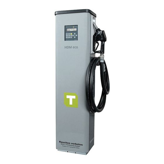
- Page 1 Operating manual HDM 60 eco / HDM 80 eco Item. No.: 110 700 860, 110 700 880...
- Page 2 Important! The operating manual is always to be read before commissioning the equipment. No warranty claim will be granted for faults and damage to the equipment arising from insufficient knowledge of the operating manual. Copyright © HORN GmbH & Co. KG. All rights reserved. Text, graphics and layout copyright protected.
-
Page 3: Table Of Contents
Table of content 1 1 1 1 Safety instructions Safety instructions ........ Safety instructions Safety instructions ......................................................................4 4 4 4 2 2 2 2 Technical description ........ Technical description .............................. - Page 4 12.5 Type Plate and Warning Signs ................43 Disposal ........ Disposal ......................................43 Disposal Disposal .............................................. 13.1 Return of batteries ....................43 Appendix A: Appendix A: Connection diagram – – – – HDA eco Connection diagram HDA eco ........
- Page 5 company must also ensure that the contents of the operating manual are properly understood by the personnel. Waters protection The device has been designed to handle water hazardous substances. The regulations on the operating place (e.g. Water Resources Act WHG, = ordinance on installations for handling of substances hazardous to water VAwS) must be adhered to.
-
Page 6: Technical Description
The built-in pumping equipment is designed such that reliable operation is achieved with a maximum annual consumption of 150,000 litres (HDM 60 eco) or 200,000 li- tres (HDM 80 eco) of fuel. Users with higher annual consumption rates should select an appliance from the Horn/Tecalemit dispenser range that is better suited to their application. -
Page 7: Dimensional Drawing
2.4 Dimensional drawing 44 1665 101-E HDM eco... -
Page 8: Accessories
2.5 Accessories The following accessories are available for the HDM eco dispenser: Base frame 233400373 Float switch 233400165 Level probe interface (Please indicate the serial number & 233400160 year of manufacture of the dispenser when ordering for retrofitting) Activation code fee (activation by telephone when retro- 233400470 fitting the level probe) -
Page 9: Place Of Installation
2.5 “Accessories”). 3.4 Suction line The suction line in the dispenser is equipped with a G1” internal thread (HDM 60 eco) or a G1¼” flange (HDM 80 eco). The dispenser is provided for connection to above-ground or underground tanks. The position of the suction line and the housing openings can be taken from the dimen- sional drawing (see section 2.4). -
Page 10: Electrical Connection
In the case of above-ground tanks, a suitable anti-syphon valve must be installed by the customer. The nominal diameter of the suction line must be at least DN 32 (HDM 60 eco) or DN 50 (HDM 80 eco). Suctions lines with diameters of DN32 or DN 50 may not exceed 6 m in length. -
Page 11: Installation Of The Level Probe
3.5.2 Installation of the level probe (optional) It is possible to connect a level probe (4-20 mA) to the HDA eco automatic dispenser. This makes it possible to monitor the level of fuel in the tank on the HDA eco auto- matic dispenser and to switch the pump off when the adjustable minimum level is reached. -
Page 12: Retrofitting The Level Probe Interface
3.5.3 Retrofitting the level probe interface It is possible to retrofit the optional level probe. Please contact HORN TECALEMIT Customer Service regarding this. 3.5.4 Connection of the RS232/RS422 interface It is optionally possible to transmit data from the HDM eco to a PC. -
Page 13: First Steps
3.5.4.2 RS422 connection In this case data transmission is possible up to a cable length of approx. 1200 m. An RS422-to-RS232 converter is required at the PC end and the RS422/RS485 socket modem must be plugged in on the HDM eco. The PC must have a free COM port. Connection diagram Converter IC-485SI PCB HDA eco... -
Page 14: Operation Of The Hda Eco
Operation of the HDA eco The user is guided through the operation of the HDA eco by a menu structure (shown in Appendix B:). The operating manual is orientated to this menu structure. 5.1 Switching on After switching on the HDA eco, a function test runs (display test, program version display, memory test, real-time clock test). - Page 15 A transponder tag can be used as ID instead of the code . Mixed operation (operator code and transponder tag) is possible; each ID may be assigned either a code or a transponder tag. The transponder tag needs to have a distance of 2 – 5 cm to the reader. Acceptance is indicated by a short beep tone.
-
Page 16: Dispensing Without Entering A Code (Optional)
5.2.1.3 Software version display It is possible to switch to the software version display from the input screens for the driver or vehicle identification by pressing the ‘►’ button. Display (e.g.): Version: 4.020 The display only stays as long as the “►” button is pressed! 5.2.2 Dispensing without entering a code (optional) If Code query: ‘none’... -
Page 17: Refuelling Procedure
5.2.5.1 Entry of a preselected quantity (optional) It is possible to enter a preselected quantity before drawing the nozzle. To this end the desired quantity in litres is entered directly using the numeric keys. After having pressed the first key, the display changes and indicates the preselected quantity. Display (e.g.): Pre-selection: 120 Quantity:... -
Page 18: Management Operating Mode / Main Menu
5.2.7.1 Data retrieval via USB memory stick The dispensing and system data of the HDA eco are written to a commercially availa- ble USB memory stick. The data on the USB memory stick can be processed on a PC using the HD Manager refuelling data administration program. To retrieve the data, the USB memory stick is inserted into the opening provided on the left of the auto- matic dispenser housing. -
Page 19: Dispensing Data Menu
5.3.1 Dispensing data menu The functions for the display and processing of the dispensing data are combined in this menu. The HDA eco automatic dispenser can store up to 2000 dispensing data records. The oldest data records are overwritten once the memory is full. Display (e.g.): Dispensing data menu ▼Display dispensing events... - Page 20 5.3.1.3 No. of dispensing events Display (e.g.): Dispensing: 1532 76% used The number of dispensing events saved and the memory used (in percent) are dis- played. The maximum possible number of dispensing data records that can be saved is approx. 2000. 5.3.1.4 USB report –...
-
Page 21: Totals Menu
5.3.2 Totals menu This menu comprises the functions for the display and processing of the dispensing totals, i.e. the accumulated dispensing quantities. The totals (driver / vehicle) to be processed must be selected beforehand. Display (e.g.): Totals menu ▼Driver totals Subsequently, the items for the processing of the totals can be selected in the sub- menu. -
Page 22: Ids Menu
5.3.2.3 USB report – totals A report of the counter readings is saved as text file on a USB memory stick ‘DTOTDATA.TXT’ for drivers, ‘VTOTDATA.TXT’ for vehicles ). The file can be opened on a PC using a text editor and printed. Therefore a recordable USB memory stick has to be inserted to the USB port of the automatic dispenser. - Page 23 5.3.3.1 Code A user code with one to five digits can be entered. An existing code can be deleted by confirming deletion. Instead of the five-digit code, a transponder tag can be assigned to an ID. The tran- sponder tag needs to be held at a distance of 2 – 5 cm to the reader. A beep tone indi- cates that the transponder tag has been read.
- Page 24 5.3.3.1.5 Mileage or operating hours window A mileage or operating hours window can be entered here defining the maximum permissible differences between two refuelling operations, max 9999 km or hrs. Display (e.g.): ♦ Vehicle ◄►Window:1000 km 5.3.3.1.6 Mileage or operating hours status Here the actual mileage or operating hours of a vehicle can be viewed.
- Page 25 5.3.3.3 USB report – IDs A report for the driver IDs (‘DIDDATA.TXT’) and a report for the vehicle IDs (‘VIDDA- TA.TXT’) are saved as text files on a USB memory stick. The file can be opened on a PC using a text editor and printed. Therefore a recordable USB memory stick has to be inserted to the USB port of the automatic dispenser.
-
Page 26: System Menu
5.3.4 System menu Various system parameters for the operation of the dispenser can be viewed and ad- justed in this menu. Display (e.g.): System menu ▼Dispensing options Menu items are selected with the “▲” and “▼”keys, confirmed with “ENTER ENTER ENTER ENTER”... - Page 27 5.3.4.1.4 Order y/n Display (e.g.): Order ◄►query The entry of an order no. before each dispensing is optional. You can choose between “query“ and ”no query“. 5.3.4.1.5 Dispensing limit Display (e.g.): Dispensing limit 9999 L The maximum possible dispensing quantity per refuelling operation can be specified here (absolute limit).
- Page 28 5.3.4.2.2 Decimal points Display (e.g.): Decimal points ◄►1 The number of decimal points displayed during dispensing can be displayed and changed here. You can choose between ‘0’ and ‘1’. 5.3.4.2.3 Automatic dispenser blocking Display (e.g.): Blocking automatic dispenser ◄►No Here you can set whether the automatic dispenser should be blocked for refuelling or enabled again after having been blocked.
- Page 29 5.3.4.3 Expanded menu : Expanded system settings or queries can be made here. Display (e.g.): Expanded menu ▼Real-time clock Menu items are selected with the “▲” and “▼”keys, confirmed with “ENTER ENTER ENTER ENTER” and can- celled with “EXIT EXIT”. EXIT EXIT 5.3.4.3.1...
- Page 30 The setting range extends from 0 (low contrast) to 63 (high contrast). Changing the default value should only be necessary under extreme operating conditions (very low/very high temperatures). In case the incorrect contrast has been saved inadvertently (display unreadable): Switch off the device and switch on again keeping the “EXIT EXIT EXIT”...
- Page 31 5.3.4.3.6 Configuration info This display is intended for service purposes. It provides information about the con- figuration of the automatic dispenser. Display (e.g.): Config. info 00110010 5.3.4.3.7 Release This display is intended for service purposes. It can be used to change the configura- tion of the automatic dispenser Display (e.g.): Release...
-
Page 32: Fuel Tank Menu
5.3.5 Fuel tank menu The function of the tank monitoring as well as tank parameters (level probe option only) can be set in this menu. Display (e.g.): Tank menu ▼Tank monitoring 5.3.5.1 Tank monitoring Monitoring of the tank contents including blocking of the dispensing point in case of empty tank can be switched on or off. - Page 33 5.3.5.2.3 Level / maximum level Display (e.g.): Tank parameters 1600 ◄►Height The maximum level in mm is entered as value between 0 and 9999. 5.3.5.2.4 Density of medium Display (e.g.): Tank parameters ◄►Density 860 g/L In order for the hydrostatic tank probe to work precisely, the density of the tank me- dium [g/l] must be entered.
-
Page 34: Commissioning
every case! The disablement is automatically cancelled after refilling the tank or switching the tank monitoring off (see section 5.3.5.1). Display (e.g.): Tank parameters ◄►MinVol 5000 L 5.3.5.3 Tank contents (level probe option only) The filling quantity in percent, the measured filling level and the filling quantity in li- tres are displayed. -
Page 35: Emergency Operation
The procedure to enable the dispenser is described in detail in section 5.2. 2. Switch on the pump by drawing the nozzle. 3. Put the nozzle into the container or the vehicle tank. 4. Open the nozzle until the desired quantity has been dispensed. 5. -
Page 36: A2010 Nozzle 0 Nozzle
A2010 nozzle 9.1 Description The HDM eco dispenser is equipped with an automatic nozzle of the type A2010. It is an automatically closing full-hose nozzle for dispensing the liquids specified above. The A2010 automatic nozzle has been tested in accordance with the DIN EN 13012 standard. -
Page 37: Operating Instructions
9.4 Operating instructions The A2010 automatic nozzles are ready for use. No adjustment or lubrication needs to be carried out. Smoking is generally prohibited, also when drawing off diesel and heating oil EL. Sources of ignition, such as fire, flying sparks etc., must be eliminated. Insert the outlet pipe into the tank filler pipe to the extent that it will remain securely in the tank filler pipe (see fig. -
Page 38: Spare Parts
Flange for wall opening 516670006 Seal & screw set for counter installation 816658005 Dispensing hose, DN25 4m - HDM 80 eco 421301100 Dispensing hose, DN19 4m - HDM 60 eco 421202250 Swivel joint for wall opening G1” IA 406537170 A2010 nozzle 405301800 Swivel joint for nozzle G1”... - Page 39 44 1665 101-E HDM eco...
- Page 40 44 1665 101-E HDM eco...
- Page 41 44 1665 101-E HDM eco...
-
Page 42: What To Do If
Fault display – What to do if ... ? ... the pump runs, but the automatic nozzle immediately shuts off again? • The sensor pipe of the automatic nozzle is clogged: The nozzle must be cleaned..the pump runs, but no medium is pumped? •... -
Page 43: Cleaning The System
12.2 Cleaning the system Clean dirty outsides carefully with a damp cloth and gentle household cleaner. Do not use aggressive (e.g. abrasive, chlorinated) cleaning agents or solvents. The equipment must not be cleaned with a high-pressure cleaner or water jet. 12.3 Maintenance of the nozzle Make sure that the sensor jet on the outlet pipe is always open. -
Page 44: Appendix A: Connection Diagram Hda Eco
Appendix A: Connection diagram – HDA eco LEDs operating voltage Keyboard connection Lithium battery Fuse RFID antenna Pump Motor Serial interface connection Emergency Mains voltage mode switch Terminal strip Terminal Signal Mains voltage - live Mains voltage - protective earth Mains voltage - neutral Switched phase for motor L and Pu... - Page 45 Earth terminal Pulse generator operating voltage +5.2V Pulse input Pulse generator ground Enabling contact (potential-free contact) LS + Sensor (4-20 mA) operating voltage + or float switch LS - Sensor (4-20 mA) operating voltage - or float switch RFID antenna connection Display connection Keyboard connection USB port...
-
Page 46: Menu Structure: Management Operation
Appendix B: Menu structure: Management Operation Dispensing data menu Menu items are selected with the “▲” Display dispensing events and “▼” keys and confirmed by pressing Deleting dispensing events the “ENT ENT” key. No. of dispensing events USB report - dispensing events Sub-menus or menu items can be exited by pressing the “EXIT EXIT... -
Page 47: Appendix C: Data Export Or Import Via Usb Memory Stick
Appendix C: Data export or import via USB memory stick Refuelling and ID data are written as a file to the USB memory stick or read from it (ID data only). The data is processed with the HD Manager eco program. It is prefera- ble to use the USB memory stick included in the scope of supply or available as a spe- cial accessory;... - Page 48 , 1, 0, 0000, 00, 9999,BC Generation of a language file A new language file has to be examined and approved by HORN TECALEMIT. Please contact customer service at HORN TECALEMIT. A faulty language file can impair the operation of the automatic dispenser.
- Page 49 Data fields: Unique text ID (numeric, maximum three-digit) each text in the user guidance is as- signed exactly one ID Text (1 - 16 characters) translation of the original text. Characters will be cut off if the maximum text length is exceeded. Example: 0,Yes 1,No...
-
Page 50: Declaration Of Conformity
Appendix D: Declaration of conformity 44 1665 101-E HDM eco... -
Page 51: Declaration Of Conformity Of The A2010 Nozzle
Appendix E: Declaration of conformity of the A2010 nozzle Horn GmbH & Co. KG hereby declares the conformity of the A2010 automatic nozzle to DIN EN 13012 and the general building authority test certificate P-TÜ7-01340. 44 1665 101-E HDM eco... - Page 52 HORN GmbH & Co. KG Munketoft 42 24937 Flensburg Germany T +49 461-8696-0 F +49 461-8696-66 www.tecalemit.de info@tecalemit.de 44 1665 101-E HDM eco...
Need help?
Do you have a question about the HDM 60 eco and is the answer not in the manual?
Questions and answers