Table of Contents
Advertisement
Quick Links
Advertisement
Table of Contents

Subscribe to Our Youtube Channel
Summary of Contents for HIMA HIMax
- Page 1 HIMax ® System Manual SYSTEM...
- Page 2 HIMA directly. HIMA appreciates any suggestion on which information should be included in the manual. Equipment subject to change without notice. HIMA also reserves the right to modify the written material without prior notice. For further information, refer to the CD-ROM and our website http://www.hima.de and http://www.hima.com.
-
Page 3: Table Of Contents
HIMax System Table of Contents Table of Contents Introduction ............7 Structure and Use of the Document..............7 Target Audience..................... 7 Formatting Conventions ..................8 1.3.1 Safety Notes ......................8 1.3.2 Operating Tips ......................9 Safety ..............10 Intended Use ......................10 2.1.1... - Page 4 Table of Contents HIMax System Communication ....................44 Communication with the Programming and Debugging Tool......44 Licensing....................... 45 Redundancy ............46 Processor Module ....................46 4.1.1 Decreasing Redundancy ..................46 4.1.2 Upgrading Redundancy..................46 I/O Modules ......................46 4.2.1 Module Redundancy ....................46 4.2.2...
- Page 5 Connecting the Power Supply after a Service Interruption ........111 9.3.3 Connecting the redundant Power Supply ............111 9.3.4 Repair ........................112 HIMax Documentation and Support ....... 113 10.1 HIMax Documentation ..................113 10.2 HIMA Service, Training and Hotline ..............114 Appendix ..............115...
- Page 6 Table of Contents HIMax System Index of Figures....................118 Index of Tables ....................119 Index ........................121 HI 801 001 E Rev. 4.01 Page 6 of 122...
-
Page 7: Introduction
Introduction The System Manual describes the configuration and mode of operation of the safety-related HIMax controller system. HIMax can be used for various control tasks within the process and factory automation industry. Structure and Use of the Document This System Manual is composed of the following chapters:... -
Page 8: Formatting Conventions
1 Introduction HIMax System Formatting Conventions To ensure improved readability and comprehensibility, the following fonts are used in this document: Bold: To highlight important parts Names of buttons, menu functions and tabs that can be clicked and used in SILworX. -
Page 9: Operating Tips
HIMax System 1 Introduction 1.3.2 Operating Tips Additional information is structured as presented in the following example: The text corresponding to the additional information is located here. Useful tips and tricks appear as follows: The tip text is located here. -
Page 10: Safety
Use in Fire Alarm Systems All HIMax systems with analog inputs are tested and certified for used in fire alarm systems in accordance with DIN EN 54-2 and NFPA 72. To contain the hazard, these systems must be able to adopt an active state on demand. -
Page 11: Operating Requirements
IEC/EN 61000-6-4 Electromagnetic Compatibility (EMC) Generic emission standard, industrial environments Table 1: Standards for EMC, Climatic and Environmental Requirements When using the safety-related HIMax control systems, the following general requirements must be met: Requirement type Requirement content Protection class Protection class II in accordance with IEC/EN 61131-2... -
Page 12: Table 5: Interference Immunity Tests
2 Safety HIMax System EMC Requirements Higher interference levels are required for safety-related systems. HIMax systems meet these requirements in accordance with IEC 62061 and IEC 61326-3-1. See column 'Criterion FS' (Functional Safety). Test standards Interference immunity tests Criterion IEC/EN 61000-4-2... -
Page 13: Requirements To Be Met By The Operator And The Machine And System Manufacturers
The operator and the machine and system manufacturers are responsible for ensuring that HIMax systems are safely operated in automated systems and plants. The machine and system manufacturers must validate that the HIMax systems are correctly programmed. Residual Risk No imminent danger results from a HIMax system itself. -
Page 14: Safety Precautions
Observe all local safety requirements and use the protective equipment required on site. Emergency Information A HIMax controller is a part of the safety equipment of a system. If the controller fails, the system adopts the safe state. In case of emergency, no action that may prevent the HIMax systems from operating safely is permitted. -
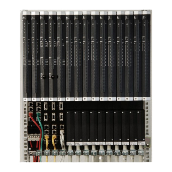
Page 15: Product Description
The controller can be easily adapted to future extensions of the process to be controlled, e.g., by adding modules or base plates containing modules. Figure 1 shows the structure of the HIMax system. The figure shows the base plates, both system busses, the system bus modules, the processor modules and the Connector Boards of the modules. -
Page 16: Base Plates And Base Plate Types
Figure 1: System Overview A HIMax system is composed of at least one rack, i.e., rack 0. It has rack ID (e.g., 0) und contains at least one processor module. All additional racks are extension racks. Among these, rack 1 may contain one or two processor modules. The remaining racks must contain no processor modules. -
Page 17: Base Plate Structure
HIMax System 3 Product Description Base plate types: With 10 slots: X-BASE PLATE 10 01 for mounting on a flat base, e.g., a mounting plate. With 15 slots: X-BASE PLATE 15 01 for mounting on a backplane With 15 slots: X-BASE PLATE 15 02... -
Page 18: Ventilation
10 kVA is allowed. The power supply used must have a momentary interruption immunity value of < 10 ms. HIMA power supply units are appropriately equipped. Before using power supply units from other manufacturers, ensure their adequate testing. -
Page 19: System Bus
Power consumption of the actuators connected to and supplied by the output modules The power in watts required for one HIMax system is the result of this rough calculation. For an exact calculation of the power required, use the power consumption values of the individual modules as specified in the corresponding manuals. - Page 20 The system busses are not normal Ethernet connections. Therefore, the RJ-45 sock- ets UP and DOWN and DIAG may only be used to connect to HIMax racks. Do not connect the sockets UP and DOWN and DIAG to local networks or other de-...
-
Page 21: System Bus With Line Structure
HIMax System 3 Product Description 3.2.1 System Bus with Line Structure Two adjacent base plates can be connected to one base plate. Figure 3: Arrangement of Racks on the System Bus A rack sequence results from interconnecting the racks – see Figure 3. - Page 22 The connection may have a maximum latency of 10 µs. HIMA recommends to also connect racks 0 and 1 directly, even if only rack 0 contains processor modules. Thus, a later expansion with processor modules in rack 1 is possible.
-
Page 23: Figure 4: System Bus With Network Structure
HIMax System 3 Product Description Figure 4: System Bus with Network Structure HI 801 001 E Rev. 4.01 Page 23 of 122... -
Page 24: Extending The System Bus, System Bus Latency
In a network structure, the system bus module cannot prevent Ethernet rings from occurring. A faulty network structure can cause a part or the entire HIMax system to shut down. SILworX always represents the system in a line structure. 3.2.3 Extending the System Bus, System bus Latency The system bus is based on Ethernet technology. -
Page 25: Table 8: Default Values For Maximum System Bus Latency
I/O modules can then be located up to 9.8 km from the processor modules. The HIMax system can have a maximum extension of up to 19.6 km (Figure 5). HI 801 001 E Rev. 4.01 Page 25 of 122... -
Page 26: Figure 5: Maximum Distance For Latency Default Value
(Figure 6). The two racks with processor modules may be located up to 1.8 km far from one another. In this case, the HIMax system can have a maximum extension of 17.4 km. HI 801 001 E Rev. 4.01... -
Page 27: Figure 6: Maximum Distance Between Processor Modules With Latency Default Value
HIMax System 3 Product Description 1 800 m 7 800 m 7 800 m 17 400 m Rack with I/O Modules Converter Copper Cable <-> Fiber Op- tic Cable Rack with Processor Modules Fiber Optic Cable Ethernet Copper Cable Figure 6:... -
Page 28: Figure 7: Connection Of Two Base Plates Through A Fiber Optic Cable
3 Product Description HIMax System Rack A, connected to switch X Fiber Optic Cable Rack B, connected to switch Y Switch X: Hirschmann SPIDER II Giga 5T/2S EEC Rail Switch Copper cable between rack B and switch Y Copper Cable Between Rack A and... - Page 29 When designing the network structure and calculating the maximum latency, HIMA recommends to consult a network expert . Example for Calculating a User-Specific Maximum Latency The racks in Figure 8 are respectively connected to one another and to the switches with 100 m copper cable.
-
Page 30: Figure 8: Example For Calculating The System Bus Latency
3 Product Description HIMax System Rack 0 Connected to Port 1 of Switch Switch C: Hirschmann SPIDER II Giga 5T/2S EEC Rail Switch with Port Num- Racks 1, 2, 3 Connected to Port 2 of Switch A Switch B: Hirschmann SPIDER II Giga... - Page 31 HIMax System 3 Product Description In this example, the following values are assumed for calculating the maximum system bus latency: Internal switch latency 5 µs Switch Light velocity 300 000 km/s Damping Fiber optic cable damping 2 is assumed Fiber optic cable...
- Page 32 3 Product Description HIMax System Explanation: 2 copper cable between racks 8, 7 and switch A, switch A and rack 0 Delay due to switches A and B Switch Number of base plates, here 16 Racks -1)*t Latency for the following racks:...
-
Page 33: Modules And Connector Boards
For more information on connector boards and field termination assemblies, refer to the module manuals. 3.3.1 Identifying the Module via SRS The HIMax system uses the parameters System, Rack, Slot (SRS) to identify the modules. Designation Range of values Description System 1...65 535... -
Page 34: Permissible Slot Assignments
3 Product Description HIMax System Every device, e.g., remote I/O that can be reached in a network must be assigned a unique SRS. 3.3.2 Permissible Slot Assignments The slot assignment is defined as follows: 1. Slot 1 and slot 2 on each base plate are reserved for system bus modules. -
Page 35: Processor Module
HIMax System 3 Product Description HIMA recommends to use variant 3 even if variant 1 would be possible. In doing so, the processor module can be replaced without interrupting operation. Since the operating system is designed to ensure maximum availability, other combinations are possible, but not recommended. -
Page 36: Table 11: Operating System States, Adopting The States
3 Product Description HIMax System State Description The state is adopted LOCKED Emergency state: The processor Connecting the operating voltage to the module is reset to the factory set- processor module while the mode switch is tings (SRS, network settings, set to Init. -
Page 37: Behavior In The Event Of Faults
Once the processor module has normally run for approximately one minute, an error stop is considered again as first error stop. Noise Blanking This chapter describes how noise blanking of I/O modules operates in the HIMax system. 3.5.1 Impact of Noise Blanking Noise blanking suppresses transient noise to increase the system availability. -
Page 38: Configuring Noise Blanking
3 Product Description HIMax System The maximum noise blanking time can be determined with the following formula: Max. noise blanking time = safety time - (2 * watchdog time) The greater the noise blanking time value, the longer the interference can be blanked out. -
Page 39: Noise Blanking Sequence
HIMax System 3 Product Description 3.5.3 Noise Blanking Sequence The examples illustrate the sequence of noise blanking: A transient interference is blanked out. An existing interference - longer than the maximum noise blanking time - triggers the safe reaction. Example 1: Transient Interference is Successfully Blanked Out... -
Page 40: Figure 10: Interference Triggers Safe Reaction
3 Product Description HIMax System Example 2: Safe Reaction within the Safety Time if an Interference is Present Cycle, Duration = Watchdog Time Processing (in all Cycles) Read-in Process in 1 Cycle Output Process in 1 and 2 Cycle Read-in Process 2... -
Page 41: Considering The Effective Direction
HIMax System 3 Product Description 3.5.4 Considering the Effective Direction The effective direction must be observed when considering noise blanking and output noise blanking, see Figure 11 and the following chapter. Sensor Actuator System Bus, Effective Direction from the Input... -
Page 42: Alarm And Sequence Of Events Recording
3 Product Description HIMax System DANGER If the output noise blanking is active, the time values set in the HIMax system must be recalculated. Take into account that a safe reaction to an existing interference can be delayed up to 2 * safety time if a transient interference is suppressed by the processor module (X-CPU) as well as by the output noise blanking. -
Page 43: Recording Events
HIMax System 3 Product Description Creating Events on SOE Modules SOE modules can create events using the input states. The events are created in the SOE module cycle. The SOE module stores the events in the intermediate buffer that the processor modules use to read them. -
Page 44: Communication
The protocol is activated. Communication with the Programming and Debugging Tool A HIMax controller communicates with a PADT via Ethernet. A PADT is a computer that is installed with the SILworX programming tool. The computer must be able to reach the controller via Ethernet. -
Page 45: Licensing
Some communication protocols, see the communication manual (HI 801 101 E) For the network structure function of the HIMax systems, a license must be purchased from HIMA. To activate the function, HIMA provides a license code which must be entered with the PADT in the configuration. -
Page 46: Redundancy
Processor Module A HIMax system can be configured as mono system with only one processor module or as highly available system with up to four redundant processor modules. A system with redundant processor modules always requires a redundant system bus. -
Page 47: Channel Redundancy
For more information on these Connector Boards, refer to the module manuals. System Bus The HIMax system has two redundant system buses, system bus A and system bus B. Requirements for redundant operation: Use of two system bus modules per base plate. - Page 48 L2+/L2- used for the redundant power supply unit. Each module supports internal decoupling of the operating voltage from the two terminals. A redundant supply external to the HIMax system must be provided for connector boards with external supply.
-
Page 49: Programming
5 Programming Programming The user programs for the HIMax system must be created using the programming system (PADT) which is composed of one PC with the programming tool SILworX. A user program is composed of standard function blocks in accordance with IEC 61131-3, of user-defined function blocks and of variables and connectors. -
Page 50: Initial Value
The value that the connected variables should adopt can be set for safeethernet and communication protocols. HIMA recommends to assigning a safe value as initial value to all variables that receive their value from a physical input or from communication! Variables to which no initial value was assigned, have initial value 0 or FALSE if the variables are of type BOOL. -
Page 51: Table 15: System Variables At Different Project Levels
HIMax System 5 Programming Project level Description of the system variables and system parameters Resource See Table 16 System variables for configuring the controller, see Table 17. Hardware, in general System variables providing information, seeTable 18. Hardware: Modules See the manual of the corresponding module type. - Page 52 5 Programming HIMax System 5.2.3.1 The System Parameters of the Resource The system parameters of the resource can be set in SILworX, in the Properties dialog box of the resource. Parameter / Description Default Setting for safe Switch value operation...
- Page 53 Dynamic HIMax maintains the target cycle time as well as possible, but it also executes the cycle as quickly as possible. Minimum Con-...
-
Page 54: Table 16: Resource System Parameters
This slows down the process data communication, but it also ensures that all connections to external partners are processed equally and completely. For firmware HIMax CPU V3, the value of the maximum duration of configuration connections in SILworX is set to 6 ms by default. The time required to process communication with external partners may, however, exceed the default value in a CPU cycle. -
Page 55: Table 17: The Hardware System Variables For Setting The Parameters
These parameters are used to ensure that the cycle time is constantly maintained to the Target Cycle Time [ms] value. To do this, this parameter must be set to a value ≠ 0. HIMax reduces the reload and synchronization tasks of redundant modules to such an extent that the target cycle time can be maintained. - Page 56 5 Programming HIMax System To make one of the system variables Force Deactivation, Read-only in Run or Reload Deactivation operable with the key switch: 1. Assign a global variable to a system variable. 2. Assign the same global variable to a digital input.
- Page 57 HIMax System 5 Programming 5.2.3.3 Hardware System Variables for Reading the Parameters These system variables can be accessed in the SILworX Hardware Editor. To this end, select the dark-gray background outside the base plate symbols. Double-click or use the context menu to open the detail view.
- Page 58 5 Programming HIMax System Variable Description Data type 01-01 Last IO Warning [s] UDINT Last Communication Warn- UDINT ing [ms] Date and time of the last communication warning in s and ms since 1970-01-01 Last Communication Warn- UDINT ing [s]...
-
Page 59: Table 18: Hardware System Variables For Reading The Parameters
HIMax System 5 Programming Variable Description Data type Start Cycle TRUE during the first cycle after starting, otherwise FALSE BOOL Power Supply State [1]...[4] Bit-coded state of the power supply units in the processor mod- BYTE ules 1...4 Bit no. -
Page 60: Table 20: System Parameters Of The User Program
5 Programming HIMax System 5.2.3.4 System Parameters of the User Program The following user program switches and parameters can be set in the Properties dialog box of the user program: Switch / Function Default Setting for value Parameter safe operation... -
Page 61: Assignment To I/O Channels
As an easier alternative, the process value of the REAL data type can be often used instead of the "raw value". HIMax calculated the process value based on the raw value and the scale value on the parameters 4 and 20 mA. Refer to the module manual for more details. - Page 62 5 Programming HIMax System 4. In the user program, program a safety-related fault reaction using the statuses Channel OK, SC, OC (if necessary others). The user program can process the measuring in a safety-related manner. If the value 0 for a channel is within the valid measuring range, the user program must, at a minimum, evaluate the parameter Channel OK in addition to the process value.
-
Page 63: Assignment To Communication Connections
HIMax System 5 Programming Use of Analog Outputs Perform the following steps to write a value in the user program to an analog output 1. Define a global variable of type REAL. 2. When defining the global variable, enter the initial value as safe value. -
Page 64: Table 21: Parameters For Boolean Events
5 Programming HIMax System Column Description Range of Values Name Name for the event definition; it must be unique within the Text, max. 32 charac- resource. ters. Global variable Name of the assigned global variable (added using a drag&drop operation) Data type Data type of the global variable;... - Page 65 HIMax System 5 Programming Column Description Range of Values Name Name for the event definition; it must be unique within the re- Text, max. 32 charac- source. ters Global variable Name of the assigned global variable (added using a drag&drop operation) Data type Data type of the global variable;...
-
Page 66: Forcing
When forcing values, the person in charge must take further technical and organizational measures to ensure that the process is sufficiently monitored in terms of safety aspects. HIMA recommends to set a time limit for the forcing procedure, see 5.3.1. Forcing can operate at two levels: Global forcing: Global variables are forced for all applications. -
Page 67: Restricting The Use Of Forcing
HIMax System 5 Programming It is also possible to define how the HIMax system should behave upon expiration of the time limit: With global forcing, the resource is stopped or continues to run. With local forcing, the user program is stopped or continues to run. -
Page 68: Multitasking
In such cases, the corresponding status variables must also be forced! Multitasking Multitasking refers to the capability of the HIMax system to process up to 32 user programs within the processor module. This allows the project's sub-functions to be separated from one another. The individual user programs can be started, stopped and loaded independently by performing a reload. -
Page 69: Figure 12: Cpu Cycle Sequence With Multitasking
HIMax System 5 Programming First CPU Cycle Considered Input Processing in the Second CPU Cycle Second CPU Cycle Considered Second UP 1 Cycle Considered Input Processing in the First CPU Cycle Second Portion of the Considered UP 2 First UP 1 Cycle Considered... -
Page 70: Table 23: Parameters Configurable For Multitasking
5 Programming HIMax System Parameter Description Configurable for Max. Duration Time permitted for executing the user program User program, Multitask- for Each Cycle within a CPU cycle. ing Editor [µs] Program ID ID for identifying the program when displayed in... -
Page 71: Multitasking Mode
HIMA recommends to set the Max. Duration for each Cycle [µs] parameter to an appropriate value ≠ 0. This ensures that a user program with an excessively long runtime is stopped during the current CPU cycle and resumed in the next CPU cycle without affecting the other user programs. -
Page 72: Figure 13: Multitasking Mode
5 Programming HIMax System First CPU Cycle Considered. The UP 3 Max. Duration for Each Cycle [µs] has Expired, Completion of the Second CPU Cycle Considered. Second CPU Cycle. Third CPU Cycle Considered. The next User Program Cycle of UP 1 The Max. -
Page 73: Figure 14: Multitasking Mode
HIMax System 5 Programming 2. In multitasking mode 2, the unneeded duration of lower-priority user programs is distributed among higher-priority user programs. In addition to the specified Max. Duration for Each Cycle [µs], these user programs can use the portions of unneeded duration. -
Page 74: Figure 15: Multitasking Mode
5 Programming HIMax System The unused execution time of user programs that were not run cannot be exploited as residual time by other user programs. User programs are not run if they are in one of the following states: STOP... -
Page 75: Loading User Programs
It is possible to abort the reload procedure and to modify the watchdog and target cycle times in order to allow the reload. If a user program already running in a controller is modified, HIMax allows one to load the modified version into the controller by performing a reload. While the previous version of the user program is still running, the new version is stored in the controller memory, tested and provided with the variable values. - Page 76 Plan sufficient time reserve for the watchdog time and the target cycle time to be able to perform the reload. HIMA recommends the procedure in safety manual (HI 801 003 E) to evaluate the watchdog time. The watchdog and target cycle times can be increased for the duration of the reload, refer to the SILworX online help for more details.
-
Page 77: Table 24: Reloading After Changes
HIMax System 5 Programming Take the following point into account when reloading actions: During the reload, actions are loaded with their corresponding data. All potential consequences must be carefully analyzed prior to performing a reload. Examples: If a timer action qualifier is deleted due to the reload, the timer expires immediately. -
Page 78: Loading Operating Systems
Loading Operating Systems All HIMax system modules contain one processor system and one operating system that controls the module. The operating system is delivered with the module. HIMA is continuously improving the operating systems. The improved versions can be loaded into the module using SILworX. -
Page 79: Updating And Downgrading Operating Systems
HIMax System 5 Programming No further actions may be performed on the system during the upgrading process! Prior to upgrading the operating systems, the HIMax system must be in a faultless state! NOTE Service interruption possible during the loading procedure! Ensure the operation of a functional, redundant module! The redundant module maintains operation during the loading procedure. -
Page 80: User Management
The user management for a controller (PES user management) is used to protect the HIMax controller against unauthorized access and actions. The user and its access rights are part of the project; they are defined with SILworX and loaded into the processor module. -
Page 81: Default User
HIMax System 6 User Management Creating user accounts is not necessary, but is a contribution to safe operation. A user management scheme defined for a resource must contain at least one user with administrator rights. 6.2.1 Default User The factory user settings apply if no user accounts were set up for a resource. The factory settings also apply after starting a processor module using the mode switch set to Init. -
Page 82: Parameters For User Accounts
6 User Management HIMax System 6.2.2 Parameters for User Accounts To set up new user accounts, the following parameters must be set: Parameter Description Username User name or ID to log in to a controller. The user name must not contain more than 32 characters (recommended: a maximum of 16 characters) and may only be composed of letters (A ... -
Page 83: Diagnosis
HIMax System 7 Diagnosis Diagnosis The diagnostic LEDs are used to give a first quick overview of the system state. The diagnostic history in SILworX provides detailed information. Light Emitting Diodes Light emitting diodes (LEDs) on the front plate indicate the module state. All LEDs should be considered together. -
Page 84: Module Status Indicators
Description Yellow Do not remove the module! The module is absolutely required for operating the HIMax system. Only one module is configured. Blinking1 Do not remove the module! The module is absolutely required for operating the HIMax system. Multiple redundant modules are config- ured. -
Page 85: System Bus Indicators
HIMax System 7 Diagnosis 7.1.4 System Bus Indicators The system bus LEDs are labeled Sys Bus. Color Status Description Green Physical and logical connection to the system bus module in slot 1. Blinking1 No physical connection to the system bus module in slot 1. -
Page 86: Maintenance Indicators
No module fault displayed for a HIMax system module Field Field warning, only if no field fault occurred in a HIMax system I/O module Blinking1 Field faults in an I/O module of the HIMax system... -
Page 87: I/O Indicators
HIMax System 7 Diagnosis 7.1.9 I/O Indicators The LEDs of the I/O indicators are labeled Channel and Field. Color Status Description Channel Yellow The related channel is active (energized). 1 - n Blinking2 The related channel is faulty. The related channel is inactive (de-energized). -
Page 88: Ethernet Indicators
7 Diagnosis HIMax System 7.1.11 Ethernet Indicators The Ethernet LEDs are labeled Ethernet. Color Status Description Eth 1…4 Green Communication partner connected No communication detected on interface Blinking-x Communication detected on interface. Blinking1 IP address conflict detected All Ethernet LEDs are blinking... -
Page 89: Diagnostic History
These messages only indicate a module fault if they occur after the system starts operation. Online Diagnosis The Online View in the SILworX Hardware Editor is used to diagnose failures in the HIMax modules. Failed modules are signalized by a color change: Red indicates severe failures, e.g., that the module is not inserted. - Page 90 7 Diagnosis HIMax System Information Representa- Range of Description tion values S.R.S Three deci- 0...65535, Module identification mals 0...15, 1...18 Module state Text e.g., STOP, State text indicating the operating state of the module. Inserted Text Permissible Type of the module actually inserted in the base...
-
Page 91: Specifications, Dimensioning
Password Project Resource Configuration Table 43: Dimensioning of a HIMax Controller Detailed specifications are provided in the manuals for the individual components and in the communication manual (HI 801 101 E). HI 801 001 E Rev. 4.01 Page 91 of 122... -
Page 92: Lifecycle
9.1.2 Connecting the Field Zone to the I/O Module HIMax is a flexible system designed for continuous operation. It allows the I/O modules to be connected to the field zone: directly, via the connector boards. indirectly, via the field termination assemblies. -
Page 93: Figure 16: Wiring 1 - Single Connector Board With Screw Terminals
HIMax System 9 Lifecycle Sensor or Actuator Redundant Sensor or Actuator Figure 16: Wiring 1 - Single Connector Board with Screw Terminals With wiring 1, connector boards of type 01, e.g., X-CB 008 01, are required in the base plate. -
Page 94: Figure 17: Wiring 2 - Redundant Connector Board With Screw Terminals
9 Lifecycle HIMax System Sensor or Actuator Figure 17: Wiring 2 - Redundant Connector Board with Screw Terminals With wiring 2, connector boards of type 02, e.g., X-CB 008 02, are required in the base plate. Wiring 3 Connect the sensors or actuators to a single connector board with cable plug via field termination assembly. -
Page 95: Figure 18: Wiring 3 - Single Connector Board With System Cable
HIMax System 9 Lifecycle Sensor or Actuator Field Termination Assembly Redundant Sensor or Actuator System Cable Figure 18: Wiring 3 - Single Connector Board with System Cable With wiring 3, connector boards of type 03, e.g., X-CB 008 03, are required in the base plate. -
Page 96: Earthing
(EMC). Perform this functional earth in the control cabinet so that it meets the requirements for protective earth. All HIMax systems can be operated with earthed L- or unearthed. Unearthed Operation In unearthed operation, one single earth fault does not affect the safety and availability of the controller. - Page 97 European Union must be labeled with the CE conformity marking for electromagnetic compatibility (EMC). All modules of the HIMA system family "HIMax" are labeled with the CE conformity marking. When installing controllers in control cabinets and support frames, ensure proper and interference-free electrical installation in the vicinity of the controllers to prevent EMC problems.
-
Page 98: Figure 20: Earthing Connections In The Control Cabinet
9 Lifecycle HIMax System Shielding on the roof sheet connected Shielding and earthing of moveable to the cabinet frame with standard fas- cabinet parts connected to the cabinet teners frame with earthing straps Shielding and earthing on the side pan-... -
Page 99: Figure 21: Earthing And Shielding The 19" Control Cabinet
Cabinets Figure 21: Earthing and Shielding the 19" Control Cabinet Mounting the HIMax on a Pivoting Frame The components of the cabinet frame are welded together and function as electrical conductive construction element. Short earthing straps with cross-sections of 16 mm² or 25 mm²... -
Page 100: Figure 22: Earth Connections For Base Plate
9 Lifecycle HIMax System Pivoting frame Cabinet Frame Screws and washers Earthing Strap 25 mm Figure 22: Earth Connections for Base Plate Earthing Connections The following table provides an overview of the dimensions of earthing connectors: Place of installation Cross-section... -
Page 101: Electrical Connections
Lay field cables for sensors and actuators separately from the power supply lines and sufficiently distant from electromagnetic active devices (electric motors, transformers). Ensure that the cables to the input modules of the HIMax systems are laid as interference- free as possible, e.g., as shielded cables. This particularly applies to cables with analog signals and proximity switches. - Page 102 9 Lifecycle HIMax System Notwithstanding HIMA standard, other cable colors can be used for wiring due to national standard requirements. In such a case, please document and verify the deviations. Connecting the Operating Voltage Connect the operating voltage supply lines to the clamp terminal blocks (L1+, L2+, L1-, L2- Attach the operating voltage supply lines of the system fan to the screw terminal connector blocks.
-
Page 103: Mounting A Connector Board
HIMax System 9 Lifecycle A non-redundant connection is established 3. Plug a RJ-45 connector of a second patch cable in to the UP socket located on the connector board of the right system bus module within the first base plate. -
Page 104: Considerations About Heat
Considerations about Heat The increased integration level of electronic components causes a corresponding lost heat. This depends on the external load of HIMax modules. Depending on the structure, the device installation and ventilation are thus of importance. Observe the environmental requirements when mounting the devices. Low operating temperature increases the product life and the reliability of the electronic components within the systems. - Page 105 HIMax System 9 Lifecycle Heat Dissipation A closed enclosure or a closed cabinet must be designed such that the heat generated inside can be dissipated through the surface. Choose the mounting type and position such that heat dissipation is ensured.
-
Page 106: Start-Up
Part 507 (HD 528 S2). All considerations about heat must take every component within a cabinet or enclosure into account, also components that are not directly part of the HIMax system! Temperature State/Operating Temperature The controllers are intended for operation up to a maximum temperature of 60 °C. The temperature states of the individual modules or controllers are centrally evaluated by the processor module. -
Page 107: Starting-Up The Control Cabinet
Init). All remaining modules are in STOP. The PADT network connection is configured such that the modules of the HIMax base plate can be reached: if required, enter routing for the used interface card. To start up the controller 1. - Page 108 This is particularly important during the initial operation of a processor module that was previously used. HIMA recommends: Reset to the factory settings (master reset) when using processor modules with an unknown past. - Set the IP address and the SRS on the processor module.
-
Page 109: Assigning The Rack Id
Since the rack ID is a safety-critical parameter, it may only be changed using the de- scribed procedure! 9.2.4 Switching Between Line and Network Structure The HIMax system can only switch between line structure and network structure by switching the mode of the system bus modules. 9.2.4.1 Switching to Network Structure Requirements for switching the system bus mode to network structure: The base plates are connected with a line structure. -
Page 110: Maintenance And Repairs
5. If the mode of system bus A is set to Network and connected, switch system bus B. To do so, perform steps 2 through 3 for the right system bus modules. The HIMax system operates with a network structure. The base plates can be reconnected with the required structure. -
Page 111: Disturbances
9.3.2 Connecting the Power Supply after a Service Interruption After connecting power supply, the HIMax system modules start in random order. This applies for the HIMax modules as well as for the connected remote I/Os. 9.3.3 Connecting the redundant Power Supply Because of potential high currents, act with particular caution when connecting a redundant power supply during operation. -
Page 112: Repair
Repair NOTE Malfunction of the controller due to insufficient repair! Only HIMA is authorized to repair a safety-related HIMax system or the modules con- tained in it. In case of unauthorized intervention in the device, functional safety cannot be en- sured and the warranty or certification lapses. -
Page 113: Himax Documentation And Support
File number format System Manual HI 801 101 E This document! Safety Manual HI 801 003 E Safe use of the HIMax system X-BASE PLATE HI 801 025 E Base Plates X-FAN HI 801 033 E System Fan X-CPU 01... -
Page 114: Hima Service, Training And Hotline
Deadlines and the extent of actions for commissioning, testing and modifying programs and HIMA control cabinets can be agreed upon with HIMA's service department. HIMA holds training course in accordance with the current seminar program for its software programs and PES hardware. The training are usually in-house at HIMA. Refer to the Internet page at www.hima.com or contact HIMA for details about the current program and... -
Page 115: Appendix
Appendix Appendix Application Examples This chapter provides examples of how to mount the HIMax systems. I/O modules and communication modules were not taken into account. They are plugged in to the remaining slots, if required. If required, base plates with 15 or 18 slots can also be used instead of base plates with 10 slots as presented in the examples. -
Page 116: Figure 28: Himax System With Distributed Redundancy
Appendix HIMax System HIMA recommends using both system bus modules. Distributed Redundancy This system contains four redundant processor modules distributed on base plate 0 and base plate 1. Figure 28: HIMax System with Distributed Redundancy HI 801 001 E Rev. 4.01... -
Page 117: Glossary
Glossary Term Description Address Resolution Protocol: Network protocol for assigning the network addresses to hardware addresses Analog Input Connector Board Connector board for the HIMax module Communication module Cyclic Redundancy Check Digital Input Digital Output Electromagnetic Compatibility European Norm ElectroStatic Discharge... - Page 118 Figure 23: Earth Terminals of Various Control Cabinets Figure 24: Inserting the Connector Board Figure 25: Securing the Connector Board with Captive Screws Figure 26: Small HIMax System: One Base Plate, Two Processor Modules Figure 27: Minimum System without Redundancy Figure 28: HIMax System with Distributed Redundancy HI 801 001 E Rev.
- Page 119 HIMax System Appendix Index of Tables Table 1: Standards for EMC, Climatic and Environmental Requirements Table 2: General requirements Table 3: Climatic Requirements Table 4: Mechanical Tests Table 5: Interference Immunity Tests Table 6: Noise Emission Tests Table 7: Review of the DC Supply Characteristics...
- Page 120 Maximum Number of Entries Stored in the Diagnostic History per Module Type Table 42: Diagnostic Information Displayed in the Online View for the Hardware Editor Table 43: Dimensioning of a HIMax Controller Table 19: Earthing Connectors Table 45: Locked Torque of the Screws for Connecting Wires in accordance with UL...
- Page 121 HIMax System Appendix Index alarm (see event)........42 download ..........75 analog inputs reload........... 75 use ............61 loading the operating system ....78 analoge outputs maintenance.......... 110 use ............63 maximum system bus latency, calculation base plate types ........16 .............
- Page 122 HI 801 001 E © 2011 HIMA Paul Hildebrandt GmbH + Co KG HIMax and SILworX are registered trademark of: HIMA Paul Hildebrandt GmbH + Co KG Albert-Bassermann-Str. 28 68782 Brühl, Germany Phone: +49 6202 709-0 +49 6202 709-107 HIMax-info@hima.com...
Need help?
Do you have a question about the HIMax and is the answer not in the manual?
Questions and answers