Table of Contents
Advertisement
Quick Links
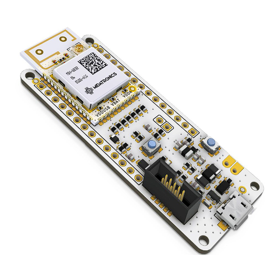
MDX-MKR-STWBU-R01 : Sharky MKR uFL antenna
All information contained in these materials, including products and product specifications,
represents information on the product at the time of publication and is subject to change
by Midatronics S.r.l. without notice.
Doc: UG_MDX-MKR-STWBx Rev 1.2
Document:
SHARKY MKR - User's Guide
SHARKY MKR
User's Guide
MDX-MKR-STWBP-R01 : Sharky MKR PCB Ant.
09/19/2019
pag. 1 of 33
Advertisement
Table of Contents

Summary of Contents for Midatronics SHARKY MKR
- Page 1 09/19/2019 SHARKY MKR User’s Guide MDX-MKR-STWBP-R01 : Sharky MKR PCB Ant. MDX-MKR-STWBU-R01 : Sharky MKR uFL antenna All information contained in these materials, including products and product specifications, represents information on the product at the time of publication and is subject to change by Midatronics S.r.l.
-
Page 2: Table Of Contents
Document: SHARKY MKR - User’s Guide 09/19/2019 Outline . Introduction 1 .1. Description 1 .2. Getting Started . System Overview 2 .1. BLE Technology Overview 2 .2. BLE Mesh Technology overview 2 .3. Thread Technology overview ... - Page 3 Figure 10. Sharky MKR connectors Figure 11. USB Interface connector Figure 12. SWD Connector Pinout Figure 13. VBATT voltage sense Figure 14. Sharky MKR Board Power Supply Figure 15. Reset button circuit Figure 16. USR/BOOT0 button circuit Figure 17. LED Circuit Figure 18.
- Page 4 Document: SHARKY MKR - User’s Guide 09/19/2019 Tables Table 1. Board Specifications Table 2. Sharky MKR pinout Table 3: SWD connector pinout Doc: UG_MDX-MKR-STWBx Rev 1.2 pag. 4 of 33...
- Page 5 Document: SHARKY MKR - User’s Guide 09/19/2019 Revisions REVISION DATE DESCRIPTION STATUS AUTHOR REVISER Ver 1.0 04/04/2019 First Release Draft info@midatronics.com UA-EM Ver 1.1 08/27/2019 Corrections Draft info@midatronics.com D6/D7 Ver 1.2 09/19/2019 Corrections Draft info@midatronics.com Disclaimer All rights strictly reserved. Reproduction in any form is not permitted without written authorization from Midatronics S.r.l.
-
Page 6: Introduction
1 .1. Description This document describes the Sharky MKR Board. Sharky MKR board is based on the Sharky module that contains an STMicroelectronics STM32WB55CE, a dual-core MCUs with wireless support, based on an Arm® Cortex®-M4 core running at 64 MHz (application processor) plus an Arm® Cortex®-M0+ core at 32 MHz (network processor). -
Page 7: System Overview
Document: SHARKY MKR - User’s Guide 09/19/2019 2 . System Overview 2 .1. BLE Technology Overview Bluetooth Low Energy (BLE) is the main feature of the Bluetooth specification v4.0 released in December 2009. BLE is a new protocol that allows for long-term operation of Bluetooth devices that transmit low volumes of data. -
Page 8: Figure 2. Ble Star-Bus Topology
Document: SHARKY MKR - User’s Guide 09/19/2019 Figure 2. BLE Star-bus Topology While BLE inherits the operating spectrum and the basic structure of the communication protocol from the classic Bluetooth protocol, BLE implements a new lightweight Link Layer that provides ultra-low power idle mode operation, fast device discovery, and reliable and secure point-to-multipoint data transfers. -
Page 9: Ble Mesh Technology Overview
Document: SHARKY MKR - User’s Guide 09/19/2019 2 .2. BLE Mesh Technology overview Figure 3. BLE Mesh Topology Borrowing from the original Bluetooth specification, the Bluetooth SIG defines several profiles — specifications for how a device works in a particular application — for low energy devices. -
Page 10: Thread Technology Overview
Document: SHARKY MKR - User’s Guide 09/19/2019 This concept is used as an inspiration for the implementation in the standard. A node in a Bluetooth Mesh network can subscribe to one or more addresses (stored in the s ubscriber list ... - Page 11 Document: SHARKY MKR - User’s Guide 09/19/2019 These are the general characteristics of the Thread stack focused on the Connected Home: ● Simple network installation, start-up, and operation : The Thread stack supports several network topologies. Installation is simple using a smartphone, tablet, or computer.
-
Page 12: Stm32Wb Wireless System-On-Chip
09/19/2019 2 .4. STM32WB Wireless System-on-Chip The Sharky MKR Board is based on STMicroelectronics STM32WB55CE, a dual-core MCUs with wireless support based on an Arm® Cortex®-M4 core running at 64 MHz (application processor) plus an Arm® Cortex®-M0+ core at 32 MHz (network processor). -
Page 13: Figure 5. Stm32Wb55Ce Pinout
Document: SHARKY MKR - User’s Guide 09/19/2019 Figure 5. STM32WB55CE pinout Figure 6. Sharky Module pinout Doc: UG_MDX-MKR-STWBx Rev 1.2 pag. 13 of 33... -
Page 14: Block Diagram
Document: SHARKY MKR - User’s Guide 09/19/2019 2 .5. Block Diagram Figure 7. Skarky MKR Block Diagram Doc: UG_MDX-MKR-STWBx Rev 1.2 pag. 14 of 33... -
Page 15: Board Specifications
Document: SHARKY MKR - User’s Guide 09/19/2019 2 .6. Board Specifications Characteristics Value CPU Clock Speed 64 MHz Flash Memory 512 Kbyte SRAM 256 KByte Connector 1 USB 1 SWD Debugger 1 battery Arduino MKR compatible pinout Board supply voltage 3.3 V to 5.5 V DC... -
Page 16: Sharky Module Block Diagram
Document: SHARKY MKR - User’s Guide 09/19/2019 2.7. Sharky Module Block Diagram Figure 8. Sharky Module with PCB Antenna / or uFL connector Doc: UG_MDX-MKR-STWBx Rev 1.2 pag. 16 of 33... -
Page 17: Connectors
Document: SHARKY MKR - User’s Guide 09/19/2019 3 . Connectors This chapter gives you an overview of the Sharky MKR board connectivity. Figure 9. Sharky MKR board pinout Doc: UG_MDX-MKR-STWBx Rev 1.2 pag. 17 of 33... -
Page 18: Arduino Mkr Connectors
Document: SHARKY MKR - User’s Guide 09/19/2019 3 .1. Arduino MKR Connectors The connectors J4 and J5 provide the user with a standard Arduino MKR shield slot as listed below. Figure 10. Sharky MKR Connectors Conn Arduino Description Sharky... - Page 19 Document: SHARKY MKR - User’s Guide 09/19/2019 J4-7 ADC1_IN10/A5 J4-8 ADC1_IN11/A6 J4-9 J4-10 J4-11 TIM1_CH1/D2 J4-12 TIM1_CH2/D3 J4-13 PA10 TIM1_CH3/D4 J4-14 PA15 TIM2_CH1/D5 J5-1 D6/LED0 J5-2 D7/SPI1_SSEL J5-3 SPI1_MOSI/D8 J5-4 SPI1_SCK/D9 J5-5 SPI1_MISO/D10 J5-6 I2C1_SDA/D11 J5-7 I2C1_SCL/D12 J5-8 USART1_RX/D13 J5-9...
-
Page 20: J1 Usb Connector
09/19/2019 3 .2. J1 USB connector The board is equipped with an USB (J1) Full-Speed (12 Mbps) device port on J1 connector. The Sharky MKR board can be powered through this interface. Figure 11. USB Interface connector Doc: UG_MDX-MKR-STWBx Rev 1.2... -
Page 21: J2 Swd/Debug Connector
Document: SHARKY MKR - User’s Guide 09/19/2019 3 .3. J2 SWD/Debug Connector The Sharky MKR board features an on-board SWD Connector (J2) that can be used to program and debug the microcontroller. Figure 12. SWD Connector Pinout Conn Description... -
Page 22: J3 Vbatt Voltage Sense
Document: SHARKY MKR - User’s Guide 09/19/2019 3 .4. J3 VBATT Voltage Sense Figure 13. VBATT voltage sense VBATT sensing is disabled by default to minimize current consumption. It can be enabled connecting J3 pins and configuring pin PA7 as analog input. -
Page 23: Usage
SHARKY MKR - User’s Guide 09/19/2019 4 . Usage This chapter describes how to connect, configure and interact with the Sharky MKR board. 4 .1. Power Supply Figure 14. Sharky MKR Board Power Supply Sharky MKR has an onboard AZ1117CR low droput linear regulator. The output voltage of the regulator is 3.3V. -
Page 24: Reset Button
Document: SHARKY MKR - User’s Guide 09/19/2019 4 .3. Reset Button Figure 15. Reset button circuit Push the button to reset the MCU 4 .4. USR/BOOT0 button Figure 16. USR/BOOT0 button circuit The USR/BOOT0 button can be pressed during reset to load the internal MCU bootloader. -
Page 25: Led
Document: SHARKY MKR - User’s Guide 09/19/2019 4 .5. LED Figure 17. LED Circuit The LD1 led is connected to the PE4/D6 pin of the M4 core. Set the pin low to lit the LED. Doc: UG_MDX-MKR-STWBx Rev 1.2... -
Page 26: Board Layout
Document: SHARKY MKR - User’s Guide 09/19/2019 5 . Board Layout The following picture show the dimensions of the Sharky MKR Board. Figure 18. Sharky MKR board dimensional drawing Doc: UG_MDX-MKR-STWBx Rev 1.2 pag. 26 of 33... -
Page 27: Firmware Upload
Document: SHARKY MKR - User’s Guide 09/19/2019 6 . Firmware Upload The STM32WB SoC inside the Sharky module has 2 cores that share the same FLASH and SRAM addresses: ● M0+ core for embedded communication stack ● M4 core for user application The module is delivered with BLE communication stack firmware installed on M0+ core and Transparent VCP firmware on M4 core. -
Page 28: Fw Upload To M0+ Core
Document: SHARKY MKR - User’s Guide 09/19/2019 6 .2. FW upload to M0+ core The M0+ firmware cannot be uploaded using STLink programmer, only the internal bootloader is allowed to update the firmware. provides package en.stm32cubewb.zip (download from: https://www.st.com/en/embedded-software/stm32cubewb.html... - Page 29 Document: SHARKY MKR - User’s Guide 09/19/2019 ○ STM32_Programmer_CLI.exe -c port=usb1 -fwdelete ● STEP 4 : Download new wireless stack : ○ STM32_Programmer_CLI.exe port=usb1 -fwupgrade [Wireless_Coprocessor_Binary] [Install address] firstinstall=1 ● Please check B inary Install Address Table for Install@ parameter depending of the binary.
-
Page 30: Software Development
Document: SHARKY MKR - User’s Guide 09/19/2019 7 . Software Development 7 .1. STM32Cube IDE The firmware can be developed and uploaded with STLink V2 or V3 device using: ● STM32CubeMX v5.10 or superior code generator that can be downloaded from STMicroelectronics website at https://www.st.com/en/development-tools/stm32cubemx.html... - Page 31 Document: SHARKY MKR - User’s Guide 09/19/2019 ● A Windows/Linux/MacOS PC ● STM32CubeIDE ● STLink V2 or V3 device https://www.st.com/content/st_com/en/products/development-tools/hardware-develop ment-tools/hardware-development-tools-for-stm32/st-link-v2.html The ST-LINK/V2 is an in-circuit debugger and programmer for the STM8 and STM32 microcontroller families. The single wire interface module (SWIM) and JTAG/serial wire debugging (SWD) interfaces are used to communicate with any STM8 or STM32 microcontroller located on an application board.
-
Page 32: Arduino Ide
SHARKY MKR - User’s Guide 09/19/2019 7 .2. Arduino IDE The Sharky MKR board can be programmed using the Arduino IDE, loading the Stm32duino project support files. For more informations on Programming with Arduino IDE read the Programmer’s Guide PG_MDX-MKR-STWBx file. -
Page 33: References And Useful Links
Document: SHARKY MKR - User’s Guide 09/19/2019 8 . References and Useful Links 8 .1. Data Sheets and documents ● https://www.st.com/content/st_com/en/products/microcontrollers-microprocessors/st m32-32-bit-arm-cortex-mcus/stm32-wireless-mcus/stm32wb-series/stm32wbx5/stm3 2wb55ce.html ● https://www.st.com/resource/en/datasheet/stm32wb55ce.pdf ● https://www.st.com/resource/en/reference_manual/dm00318631.pdf ● https://www.st.com/resource/en/programming_manual/dm00046982.pdf 8 .2. Tools ● https://www.st.com/en/development-tools/stm32cubeide.html ● https://www.st.com/en/development-tools/stm32cubeprog.html ●...
Need help?
Do you have a question about the SHARKY MKR and is the answer not in the manual?
Questions and answers