Table of Contents
Advertisement
Advertisement
Table of Contents

Summary of Contents for Hinowa GOLD LIFT 1470
- Page 1 Technical Course GOLD LIFT 1470...
-
Page 2: Table Of Contents
TABLE OF CONTENTS 1. INTRODUCTION ..................4 Technical Data GOLD LIFT 1470 .................. 5 2. FUNCTIONING AND SAFETY DEVICES OF THE MACHINE ......6 2.1 Functioning during the translation and when the machine is stabilized ..7 2.2 Functioning during the aerial works ...........8 2.3 Emergency stop................ -
Page 4: Introduction
1. INTRODUCTION The aim of this booklet is to describe the Hinowa Gold Lift 1470 aerial platform at a technical level, dealing with the safety devices of the machine, the electric and the hydraulic systems. The description of the use of the machine is not trated in this text, but will be found in its use and maintenance manual. -
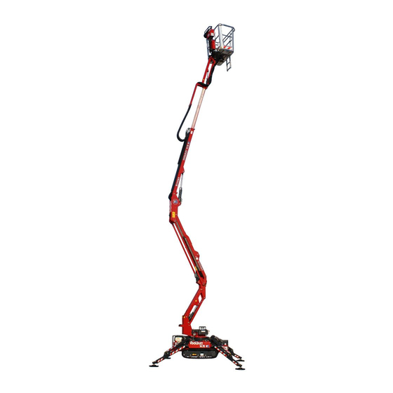
Page 5: Technical Data Gold Lift 1470
Technical Data GOLD LIFT 1470 LOADING CAPACITY 200 kg LOADING CAPACITY 120 PLATFORM’S HEIGHT (footboard) 10,58 m 11,94 m MAX. WORKING HEIGHT 12,63 m 14,00 m DIMENSIONS OF THE STANDARD BASKET 1330x694 H1100 mm WORKING OUTREACH 5,16 m 6,24 m MAX. -
Page 6: Functioning And Safety Devices Of The Machine
FUNCTIONING AND SAFETY DEVICES OF THE MACHINE The Gold Lift 1470 aerial platform is divided into two main parts: 1. Undercarriage part 2. Aerial part If you use the machine during the translation or while it is stabilized, you operate the undercarriage part;... -
Page 7: Functioning During The Translation And When The Machine Is Stabilized
2.1 Functioning during the translation and when the machine is stabilized. The translation and stabilization operations are controlled by the two valve-blocks located on the undercarriage part Both the translation and the stabilization are possible only if the machine is closed and aligned. This condition is ensured by the two photoelectric cells on the rear part of the machine. -
Page 8: Functioning During The Aerial Works
photoelectric cell is the “reflection” type. The component fixed on the arm sends a signal that, if the machine is closed and aligned, is reflected by the retroreflector located on the valve-block support. Then the signal comes back to the photoelectric cell on the arm, that sends a positive impulse to the electric panel. - Page 9 It is possible to move the aerial part only if the machine is stabilized and levelled (max 1°). This condition is signalled by the 4 flashing lamps that are on, when the outriggers lay on the ground and the machine is lifted. The pressure of the discs on the ground is signalled by the 4 micrswitches located on the 4 outriggers, that are released by the cylinder rod when the disc touches the ground.
- Page 10 Bifore lifting the machines, the operator has to choose the working load through the 120/200kg selector, located on the control panel. The Gold Lift 1470 aerial platform can work in two ways: 200kg: on the basket two people are allowed, for a max. weight of 200kg. All the functions of the...
-
Page 11: Emergency Stop
One more device controlling the movements of the aerial part of the machine is the electronic load sensor. A sensor located under the basket controls the load and checks that it is lower than the max. one foreseen for the machine and selected by the operator. In case the max. -
Page 12: Electric Emergency Descend
2.4.1 Electric emergency descend. The emergency descend procedure can be done from the basket only if the elctric system of the machine is in good order; do the following operations: keep the manual “selector 1” on the control panel pushed operate the usual arm descend controls until you reach the desired height;... -
Page 13: Emergency Descend Operated From The Ground Through The Manual Pump In Case Of Failure Of All The Systems Conveying Energy
On the valve-block on the undercarriage, singularly move the levers that control the arms, until the operator is on the ground. NOTE: in the model 1470, when you are using the emergency descend, the jib cylinder cannot be activated, then when the arm is completely down, the basket is at about 1,8 m height. In this case, in order to help the operator, you have to use an external tool (for example a ladder). - Page 14 In order to move the basket, you need to pump the oil manually and at the same time to use the controls for the arms movements located on the undercarriage. It is absolutely forbidden to make manoeuvres that are different from the above mentioned ones, such as to open the telescopic arm, to move the jib (only for the model 1470), the outriggers, and in general all the manoeuvres that could cause a loss of stability of the machine.
-
Page 15: Manual Pump
put the deviator the manual pump in the position that corresponds to the arms movements. move the selection deviator from the valve-block in the basket to the valve-block on the undercarriage; move the manual pump and at the same time move the levers of the arms movements singularly, until the operator is on the ground. -
Page 16: Hydraulic System
As soon as the emergency operations have been completed, don’t forget to remove the mechanical commutator of the deviator and to restore the standard configuration of the deviator. The presence of the mechanical commutator of the deviator during the work jeopardizes the safety of the machine, causing possible dangerous situations. -
Page 17: Functioning Of The Undercarriage Part
With the deviator you choose to convey the oil to the valveblock either of the undercarriage part or of the aerial part. If the coil is not energized, the delivery A is conveyed to the aerial part, the delivery B is conveyed to the tank. The aerial part uses only one pump. This condition happens when the machine IS NOT ALIGNED. -
Page 18: Functioning Of The Aerial Part
FUNCTIONING OF THE AERIAL PART. The delivery B that goes to the valve-blocks of the aerial part (17 and 32) is connected in parallel with a two-ways / two positions electrovalve connected with the tank and usually open. (8). See 2.4.3 If this electrovalve is NOT POWERED, the oil is conveyed to the tank, preventing the movement of the aerial part. - Page 19 The valveblocks convey the oil to the cylinders that move the machine. The setting of the machine speeds is made by registers at the sides of the valveblock, that limit the spools’ bypassing some of the oil to the tank. Such settings cannot be altered, since the speed of the machine is set by law. The connections of the hoses coming from the valveblocks both on the undercarriage and in the basket, are usually positioned on the balancing valves.
- Page 20 The extension and the rotation are exceptions; in this case the aluminium blocks make the connection. ROTATION EXTEN SION Balancing valves are flanged on all cylinders; these work both as block valves, limiting the descending speed and as anti-shock valves (20; 21; 23; 27; 24; 31). Some of these valves also include the electrovalve for the emergency descend (see 2.4.1) (20;...
-
Page 21: Functioning Of The First And Second Arm
FUNCTIONING OF THE FIRST AND SECOND ARM. On the Gold Lift 1470 aerial platform there are three arms. The first arm allows reaching the last two metres working height. The first and second arm (20 and 21) are connected in parallel. This means that the less loaded cylinder moves first. -
Page 22: Jib Functioning
BLOCK ANTI-SHOCK VALVES VALVES JIB FUNCTIONING A balancing and anti-shock valve is flanged on the jib cylinder (27). Inside this valve there is an electrovalve controlling the jib operation, according to the load that has been selected. When 200kg are selected, the electrovalve is not powered, and the oil delivered to the piston is conveyed directly to the tank. -
Page 23: Electric System
4. ELECTRIC SYSTEM In the following description we refer to the attached electric system: Attachment 2, Attachment 3, Attachment 4, Attachment 5 and to the pictures of the electric components’ housing below indicated. BATTERY TRANSFORMER... -
Page 24: Feeding Of The Main Lines F1 And 11
Feeding of the main lines F1 and 11 (Attachment 2): from the battery starts the main line that feeds the circuit: +12 and 0. From the cable +12 starts the main line F1, controlled by the engine key SC1 and by the MAIN FUSE F1 (Attachment 3). -
Page 25: Starting The Thermic Engine From The Basket
To start the thermic engine, the selector 1 on the control panel (SC-EL DIS-EM attachment 3) must be positioned on the thermic engine as in the scheme (3 open; 4 closed). When the stop button is not powered, and you push the Start button, you power the cable 2 and then, through the selector, the cable 4 (Attachment 5). -
Page 26: Starter In The Basket (Gasoline Only)
(Attachment 5) Outside the board there is the electric plug CEE 2P+T 16A that feeds the electric engine. Through the cables 230L and 230N you enter the Q1 differential switch. Then the cables L and N connect in parallel the transformer and the relay KM1, that controls the electric engine. When the PLC closes the contact Q7, the relay KM1 that closes the circuit is powered, and it feeds the electric engine. -
Page 27: Jib
I3; I4 del PLC. The exits Q1; Q2; Q3; Q4, feed the lamps ST1; ST2; ST3; ST4 located at the end of the outriggers. At the same time, the 4 contacts NC ST in series close, feeding the relay KA2. The power for these contacts comes from the cable 14 on the control panel in the basket. -
Page 28: Setting The Critical Loads
1) Connect the contacts JP1 and JP2 2) Feed the circuit board. 3) When the basket is empty, push SW1 and then SW2 (system’s zero setting); the leds DL3 and DL4 are on. 5) Push SW1 to confirm, and close the setting procedure. 6) Remove the contacts JP1 and JP2 and put them inside the circuit board’s housing. - Page 29 10) Push SW1 to confirm, and close the setting procedure. 11) Remove the contacts JP1 and JP2 and put them inside the circuit board’s housing.
-
Page 30: Summary Of The Check Operations Of The Electric System
4.8 Summary of the check operations of the electric system. -
Page 31: Possible Inconveniences: Causes And Solutions
F1: general fuse to check the feeding of the main line F1. This is to be checked if the machine doesn’t work, except the starting of the thermic engine from the key. F2: fuse that checks the feeding of the coils of: undercarriage’s electrovalve, aerial part’s electrovalve, Jib’s electrovalve. - Page 32 The block is faulty: replace it The cylinder is leaking: replace it 4) The basket doesn’t self-level There is air in the basket levelling circuit: breathe the levelling cylinder on the second transmission Anti-shockvalve on the the basket levelling cylinder is dirty or faulty: clean or replace it The self-levelling cylinders are faulty: replace them 5) The machine doesn’t start from the basket The relay KA5 is faulty: replace it...
Need help?
Do you have a question about the GOLD LIFT 1470 and is the answer not in the manual?
Questions and answers