Table of Contents
Advertisement
This manual provides brief instructions for installing and connecting the CP9000 Comfort
Controller. Please download the supplementary Installation Manual and programming guides
from
http://www.cytech.biz/installation_and_programming.html
Please read this Quick Installation and Supplementary Installation manuals before installing
Comfort
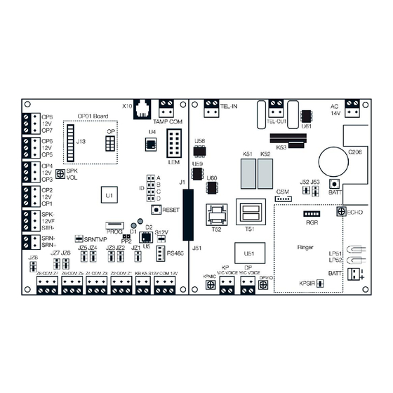
Introduction to the Comfort PCB
Please refer to the Hookup Diagram on the Lid of the Comfort Enclosure
Comfort PCB
LED Indicators
D1 (Red) LED - If Steady, system is armed. If Flashing, system is in Alert or Alarm state.
D2 Green) LED - If Steady, system is disarmed. If Flashing, system is in Trouble State.
RED (D1)
Off
Off
On
On
Flash
Flash
Flash
Off
On
Connections - Analog Section (Right Half)
AC (JP51) - Connected to Transformer secondary 14VAC (NOT Mains Voltage)
BATT (JP52) - Connected to 12V 7AH Sealed Lead-Acid Battery via supplied Battery cable.
TEL IN (MJ51) - Connection to Telephone Line
TEL OUT (MJ52) - Connection to House phones.
KP MIC/VOICE (JP53) - connection to Keypads MIC/VOICE
DP MIC/VOICE (JP54) - connection to Door Stations MIC/VOICE
GSM (J54) - connection to UCM/GSM Module audio signals.
RGR (J57) - Ringer Board RGR05 mounting
Comfort II Quick Installation Guide
GREEN (D2)
On
Flash
Off
Flash
Off
Flash
On
Off
U1 Fault, No Power, or UCM Programming cable is connected
On
STATUS
Disarmed, Normal
Disarmed, Trouble
Armed, Normal
Armed, Trouble
Alarm, Armed
Alert/Alarm, Trouble
Alarm, Disarmed
U4 File System Mismatch
Page 1 of 12
Advertisement
Table of Contents

Summary of Contents for Cytech CP9000 Comfort II
- Page 1 This manual provides brief instructions for installing and connecting the CP9000 Comfort Controller. Please download the supplementary Installation Manual and programming guides from http://www.cytech.biz/installation_and_programming.html Please read this Quick Installation and Supplementary Installation manuals before installing Comfort Introduction to the Comfort PCB...
- Page 2 Comfort II Quick Installation Guide Connections - Digital Section (Left Half) X10 (MJ1) - RJ11 socket for connection to X10 Interface. DO NOT connect a telephone line to this socket TAMP/COM (JP1 ) - Connection to Tamper of Panel and Siren/Bell box. Short the terminal ...
-
Page 3: Installation
Comfort II Quick Installation Guide Installation Location and Mounting of Panel The system should be mounted in a dry area, with access to an AC Mains power source and incoming telephone line. Mount the enclosure securely to a brick wall using Number 8 - 25 mm long screws to the 3 mounting holes as shown in the diagram above . - Page 4 Comfort II Quick Installation Guide SPK- 12VF STR- Use UL Listed strobe (Wheelock LSI-12- VSR or equivalent) 12V Strobe Speaker (8 ohm) 5W Speaker and Strobe connection The speaker may be used as an internal siren, but is not meant to be the primary audible alarm indicating device.
-
Page 5: Telephone Connections
Comfort II Quick Installation Guide Telephone Connections Connect the incoming telephone line to the TEL IN Terminal Block. Connect the telephone wires going to the house phone(s) to the TEL OUT Terminal Block. The system will work with any tone-dialling telephone. Telephones, facsimile machines and other telecommunications equipment may be connected to the Telephone OUT socket. - Page 6 Comfort II Quick Installation Guide Equipment should not be connected in parallel to the TEL IN connector except for an ADSL modem. Connection to Keyphone and PABX systems A key telephone system may be to the TEL OUT socket. To access the system with a key telephone, press the button which selects the incoming line to which the system is connected, and press *, sign-in code and # in the usual way.
- Page 7 Comfort II Quick Installation Guide Alternatively, any zone may be programmed as a Tamper zone type. Zone Input Terminals Z1-Z8 (JP3 - JP6) For US installations, all wiring shall be in accordance with the National Electrical Code ANSI/NFPA 70-1990. Each zone may be wired as Normally Closed (NC) or Normally Open (NO). Any unused zones should be programmed as Zone Type 0 with the zone inputs left open and corresponding zone header (JZ1 to JZ8) with a shunt (shorting link) in the position closer to the terminal blocks for No End Of Line resistor...
-
Page 8: Wire Smoke Detectors
Comfort II Quick Installation Guide numbers. The table below shows the expected values of circuit resistance for open and close conditions. Note that 2K7 resistor value have been replaced by 2K2. Status Measured Zone Resistance (Ohms) Closed 2 K 2 Open 7 K 4 4-wire Smoke Detectors... - Page 9 Use CSM03-CT current Tranformer and CSM03-PCB Current Sensor Pcb to monitor AC current for appliances and lights. Refer to the CSM03 manual at http://www.cytech.biz/csm_manual.htm l Output Terminals OP1 - OP8 (JP11-JP14) Each of the 8 outputs may be connected to infrared LEDs, indicator LEDs or external relays.
- Page 10 KA, KB) for longer distances. Set Each Slave to a unique ID (from 1 to 3) via the ID shunts. Each SEP01 should have their own transfomer and battery. Refer to the SEM Manual which can be downloaded from http://www.cytech.biz/expansion_module_manuals.html Keypad (KP04/KP05/KP06/KT03) and Door Stations (DP03/DM02) Up to 8 keypads and 3 Door Stations can be installed in a system.
- Page 11 Comfort II Quick Installation Guide applied. After a second, the red led should turn off, then the green LED which should blink off and on again. After a few seconds, the keypad should say “Security Off” The Green LED on the Comfort board should be on steady, and may start blinking if there is a phone trouble.
-
Page 12: Document Revision History
3.3.0 - 29 November 2012 - Initial Release Important Note The printed manual may not always be the most current version. Please check and download the latest version from http://www.cytech.biz/manuals.html web site: http://www.cytech.biz Email: info@cytech.biz Forum:: http://www.comfortforums.com Title: Comfort II Quick Installation Guide Copyright Cytech Technology Pte Ltd.
Need help?
Do you have a question about the CP9000 Comfort II and is the answer not in the manual?
Questions and answers