
Summary of Contents for Rotary Lift ML40
- Page 1 ML40, ML50 Scissor Lifts & & Rheinland © October 2006 by Rotary Lift Rev. B 03/2013...
- Page 3 EC Declaration of Conformity according to EU machine directive 2006/42/EG (Annex II A) Name and address of manufacturer: BlitzRotary GmbH Hüfinger Str.55 78199 Bräunlingen, Germany This declaration only relates to the machine in condition as supplied; components added and/or subsequent modifications made by the end user are disregarded.
-
Page 4: Table Of Contents
Contents Contents Identification and warranty ......4 Manufacturer......... . . 4 Product description . - Page 5 Contents Assembly at the installation site ......20 5.3.1 Setting up ..........20 Electrical installation .
-
Page 6: Identification And Warranty
Identification and warranty Identification and warranty Manufacturer Manufacturer: BlitzRotary GmbH Street: Hüfinger Straße 55 City/country: 78199 Bräunlingen, Germany Phone: +49 (0) 771 - 92 33-0 Fax: +49 (0) 771 - 92 33-99 E-mail: europe@rotary.com Internet: www.rotarylift.com Product description Machine type: ML 50 Machine no.: Year of construc-... -
Page 7: Warranty
Identification and warranty Warranty Every machine is covered under a 12-month warranty for material defects and faulty assembly, providing this assembly was performed by us. The warranty ex- tends to all parts which are sent to us for inspection free of charge within twelve months after delivery. -
Page 8: Product Description
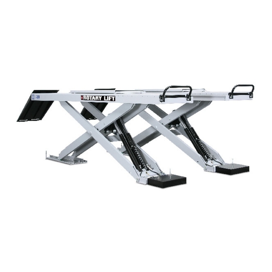
Product description Product description Mechanical design The machine consists of the following main components: • Two lifting units, each of which are made up of: – underframe – scissor assembly – running rails • Control column with integrated hydraulic unit Functional description By pressing the «Lift»... -
Page 9: Technical Data
Product description Technical data Mechanical data Load capacity: 5,000 kg Load capacity, wheel-free lift: 3,500 kg Overall height: 200 mm (N, LT) 270 mm (NAT, LTAT) Usable stroke: 1,670 mm Platform length: 4,800 mm Platform width: 729 mm Platform surface: plain sheet Weight: 3,500 kg... -
Page 10: Basic Safety Instructions
Basic safety instructions Basic safety instructions General safety information The machine was designed and manufactured under consideration of a hazard analysis and on the basis of the relevant harmonised norms as well as additional technical specifications. It corresponds to the latest technological standards valid at the time of manufacture and the relevant safety regulations. -
Page 11: Proper Use
Basic safety instructions For maintenance and inspections • Chap. 2 "Product description", page 6 • Chap. 3 "Basic safety instructions", page 8 • Chap. 7 "Operation", page 24 • Chap. 9 "Maintenance and inspections", page 29 Proper use The machine lifts vehicles continuously to any ergonomically favourable height. The permissible load capacity may not be exceeded (see load capacity plate, type plate or Chap. -
Page 12: Warning And Safety Notices Used
Basic safety instructions Warning and safety notices used Warning and safety notices contain information designed to point out the un- avoidable residual risks involved in handling the machine. The hazards apply to the following: • Persons • Machine • Equipment •... -
Page 13: Explanation Of The Icons
Basic safety instructions 3.3.3 Explanation of the icons Warning and safety notices are supplemented by visual icons if possible. An icon cannot replace the text! The text must therefore always be read in its entirety! The following icons are examples. Icon Meaning Warning of a danger to persons... -
Page 14: Technical Condition Of The Equipment
Basic safety instructions Technical condition of the equipment Safe operation places particular demands on the technical condition of the ma- chine. • Rebuilding, manipulation or making modifications to the machine is not per- mitted. This also applies to the use of replacement parts that are not supplied by us. -
Page 15: Safety Instructions In Regard To Specific Energy Systems
Basic safety instructions • The machine may only be operated, serviced and inspected by qualified and authorised personnel who have read the operating manual and perform their work accordingly. • Only operate the machine in technically flawless and functional condition. •... -
Page 16: Surface Temperature
Basic safety instructions • Do not reach into or enter the danger zone. • Avoid standing in the danger zone. • Remove any foreign objects from the danger zone. Fig. 3-1 Mechanical danger zones 3.7.4 Surface temperature Due to friction, certain components (particularly of the hydraulic system) can have high surface temperatures. -
Page 17: Safety Devices On The Machine
Basic safety instructions Safety devices on the machine 3.8.1 Deadman control The deadman control of the machine ensures that the function is only carried out as long as the operator holds the respective control pressed on the control de- vice. 3.8.2 Independent hydraulic circuits Two hydraulic circuits independent of one another prevent the unintended lower-... -
Page 18: Safety And Warning Notices
Basic safety instructions Safety and warning notices The machine is labelled with various notices. The notices should always be present and in legible condition. Note! Maximum load capacity. -
Page 19: Safety Instructions For Personnel
Basic safety instructions 3.10 Safety instructions for personnel 3.10.1 Personnel and qualifications All persons working with the machine must read the operating manual prior to be- ginning the work and confirm with their signature that they have understood what they have read and agree to observe it. •... -
Page 20: Transport
Transport Transport Basic safety instructions WARNING Suspended or falling loads Severe injuries or death • The permitted loads of the load hoisting equipment must at least correspond to the dead weight of the machine (see load capacity plate, type plate or Chap. -
Page 21: Installation
Installation Installation Basic safety instructions WARNING Scissors and castors Crushing or amputation of limbs • Do not reach or step into the danger zone (Fig. 3-1, page 14). Before setting up the machine Inspect the machine for visible signs of damage. Remove materials and objects from the work area if they are not required. -
Page 22: Assembly At The Installation Site
Installation Assembly at the installation site 5.3.1 Setting up NOTICE Incorrect setup or assembly Incorrect setup or assembly of the machine can lead to equipment damage and increased wear. • Follow the instructions for setup and assembly. Mechanical assembly work Measure the underframe of the machine and transfer the measurements to the installation site. -
Page 23: Electrical Installation
Installation Fig. 5-2 Fastening to the floor Fitting the hydraulic hoses The control column can be set up to the right or the left of the scissor lift plat- form. The connection diagrams for the hydraulic hoses are in the appendix of this operating manual. -
Page 24: Starting Up
Starting up Starting up Basic safety instructions Prior to the initial commissioning, a safety inspection must be performed by a qualified and authorised person. This person must confirm and document the technically flawless functioning of the machine. In Germany, inspection according to GUV-G 945 must be carried out. For this, use the inspection log book in the appendix of this operating manual. -
Page 25: Settings
Starting up Settings 6.3.1 Top position sensor The "top position" sensor is located on the inner side of the master lifting unit. It should be adjusted so that the lift platform stops before the hydraulic cylinders reach the upper end position. Fig. -
Page 26: Operation
Operation Operation Basic safety instructions WARNING Scissors and castors Crushing or amputation of limbs • Do not reach or step into the danger zone (Fig. 3-1, page 14). WARNING Improper placement of the load Death or severe injuries from falling loads •... -
Page 27: Description Of The Controls
Operation Before operating the machine each time, check and ensure the following: • Only authorised persons are in the work area of the machine. • No one will be endangered by the starting up of the machine. • Measures have been taken to prevent unintended changes in the position of the load. -
Page 28: Lifting And Lowering The Vehicle
Operation the «Lower» control again. The platform continues to lower at a slower speed and a warning signal sounds. 4) «Lower to latched position» control By pressing the «Lower to latched position», control, the platform lowers into the latched position. After every raising or lowering, the lift platform should be moved into the latched position. - Page 29 Operation Lowering the platform and bringing off the vehicle Press the «Lower» control and lower the platform. When the Euro Stop sen- sor is reached, the lowering motion stops. Press the «Lower» control again. The platform continues lowering more slowly. A warning tone sounds. Lower the platform completely.
-
Page 30: Shutting Down
Shutting down Shutting down WARNING High electrical voltage Severe injury or death from electrical shock • Only trained electricians may work on the electrical system. Temporary shutdown Shutting down at the end of a work shift Lower the platform completely. Turn the main switch to "0". -
Page 31: Maintenance And Inspections
Maintenance and inspections Maintenance and inspections Basic safety instructions CAUTION Hydraulic oils, lubricants and cleansers Irritation or chemical burning of eyes, skin or respiratory tract • Observe the safety instructions of the manufacturer. • Use personal protective equipment. • Use a breathing protection mask if necessary. •... -
Page 32: Maintenance Schedule
Maintenance and inspections Maintenance schedule What? When? Description Clean the machine as needed, at least 1x Chap. 9.3, page30 yearly Inspect the sliding bear- every 250 hours of oper- Chap. 9.4, page31 ings ation Check hydraulic oil level, at the yearly accident Chap. -
Page 33: Inspecting The Sliding Bearings
Maintenance and inspections Inspecting the sliding bearings Inspecting the sliding bearings Perform a visual check for wear (Fig. 9-1, page 31). The inspection is completed. Fig. 9-1 Bearing locations on the machine Servicing the hydraulic system The handling and disposal of mineral-based oils is subject to legal regulations. Bring used oil to an authorised collection point. -
Page 34: Checking The Hydraulic Oil Level
Maintenance and inspections 9.5.1 Checking the hydraulic oil level Checking the hydraulic oil level Lower the platform completely. The oil level should lie approximately 2 cm under the fill opening. Top up the oil if needed. The check of the hydraulic oil level is completed. 9.5.2 Changing the hydraulic oil Changing the hydraulic oil... - Page 35 Maintenance and inspections Fig. 9-3 Hydraulic Set the «Main lifting unit / Wheel-free lift» control (Fig. 7-1, page 25) to "Wheel-free lift". Open valves 1 and 2 (Fig. 9-3, page 33) by four revolutions. Detach plug at pos. 1 (Fig. 9-2, page 32). This will deactivate the "top posi- tion"...
- Page 36 Maintenance and inspections Repeat the following steps until the synchronisation of the platforms is achieved: Open valves 1 and 2 by four revolutions. Set the platform down on the rests («Lower to latched position» control). Unscrew the bleeder screws (6) on the hydraulic cylinders approximately 3 to 4 revolutions and allow the air to escape.
-
Page 37: Aerating The Hydraulic System Of The Wheel-Free Lift (Lt/Ltat Version Only)35
Maintenance and inspections Aerating the hydraulic system of the wheel-free lift (LT/LTAT version only) Fig. 9-4 Bleeding screw on wheel-free lift Lower the wheel-free lift. Move the main lifting unit to a midway working position and set it down on the safety latches. -
Page 38: Checking The Hydraulic Hoses
Maintenance and inspections Carefully operate the «Lift» control (inching mode) until the slave cylinder reaches the stop. Switch off the filling valve Y7 (switch S8 in the control column). Repeat the following steps until the synchronisation of the wheel-free lifts is achieved: Press the «Lower»... -
Page 39: Additional Inspections
Maintenance and inspections Performing the inspection Copy the inspection list (Chap. 9.6.3 "Inspection list", page 38). Inspect every item and check it off if OK. Only put the machine back into operation if all points have been checked off. After completing the inspection, file the inspection list behind the appendix in this operating manual. -
Page 40: Inspection List
Maintenance and inspections 9.6.3 Inspection list Sequential no.: Machine type: Machine no.: Inspector: Mechanical system Cylinder studs secured Scissors bolts secured Machine in clean condition Notices present and legible Welded points undamaged All screw connections are tight Hydraulic system No leaks in the hydraulic system Oil level is sufficient (Chap. -
Page 41: Help For Malfunctions
Help for malfunctions 10 Help for malfunctions Please contact our customer service department. This prevents damage due to improperly performed work, saves time and avoids unnecessary costs. 10.1 Machine does not lift Cause Solution Machine overloaded Reduce the load Leak in hydraulic system •... -
Page 42: Machine Does Not Lower (Completely Down)
Help for malfunctions 10.4 Machine does not lower (completely down) Cause Solution Obstacle (dirt) in the area of the roller Clean the area of the roller bearings bearings Solenoid on lowering valve defective Replace the solenoid Lowering valve defective Replace lowering valve Solenoid valve plug defective Replace solenoid valve plug Controller fuse defective... -
Page 43: Appendix
Appendix 11 Appendix... - Page 44 Appendix Mechanical components...
- Page 45 Appendix Pos. Description Art. no. Note Bearing pin R435-4-2-1 Bearing pin 12.16.410 Bushing 10.02.297 Gear rod R400-ZY-1 Lever R435-6-1 Rocker 50.51.012 Bearing pin 12.16.448 Bushing 10.02.287 Bushing 10.02.297 Castor R435-5-2-1 Bearing pin 52.82.085 Bushing 10.02.287 Bearing pin 10.16.405 Bushing 10.02.294 Bushing 10.02.284 Sliding block...
- Page 46 Appendix Mechanical components...
- Page 47 Appendix ML 40/50 N Pos. Description Art. no. Note Control column 11.34.190 Cover 56.81.029 Thread grooving screw 12.54.112 DIN 7500-CM5x8-St-Z Edge guard 55.38.078 290 mm Cylinder screw 12.54.184 DIN 912-M6x30-10.9 Washer 12.40.040 ISO 7093-6-100HV Louvered plate 56.91.352 Thread grooving screw 12.54.112 DIN 7500-CM5x8-St-Z Hydraulic unit...
- Page 48 Appendix ML 40/50 N with preset position II Pos. Description Art. no. Note Control column 11.34.190 Cover 56.81.029 Thread grooving screw 12.54.112 DIN 7500-CM5x8-St-Z Edge guard 55.38.078 290 mm Cylinder screw 12.54.184 DIN 912-M6x30-10.9 Washer 12.40.040 ISO 7093-6-100HV Louvered plate 56.91.352 Thread grooving screw 12.54.112...
- Page 49 Appendix ML 40/50 NAT Pos. Description Art. no. Note Control column 11.34.190 Cover 56.81.029 Thread grooving screw 12.54.112 DIN 7500-CM5x8-St-Z Edge guard 55.38.078 290 mm Cylinder screw 12.54.184 DIN 912-M6x30-10.9 Washer 12.40.040 ISO 7093-6-100HV Louvered plate 56.91.352 Thread grooving screw 12.54.112 DIN 7500-CM5x8-St-Z Hydraulic unit...
- Page 50 Appendix ML 40/50 NAT with preset position II Pos. Description Art. no. Note Control column 11.34.190 Cover 56.81.029 Thread grooving screw 12.54.112 DIN 7500-CM5x8-St-Z Edge guard 55.38.078 290 mm Cylinder screw 12.54.184 DIN 912-M6x30-10.9 Washer 12.40.040 ISO 7093-6-100HV Louvered plate 56.91.352 Thread grooving screw 12.54.112...
- Page 51 Appendix ML 40/50 LT Pos. Description Art. no. Note Control column 11.34.190 Cover 56.81.029 Thread grooving screw 12.54.112 DIN 7500-CM5x8-St-Z Edge guard 55.38.078 290 mm Cylinder screw 12.54.184 DIN 912-M6x30-10.9 Washer 12.40.040 ISO 7093-6-100HV Louvered plate 56.91.352 Thread grooving screw 12.54.112 DIN 7500-CM5x8-St-Z Hydraulic unit...
- Page 52 Appendix ML 40/50 LT with preset position II Pos. Description Art. no. Note Control column 11.34.190 Cover 56.81.029 Thread grooving screw 12.54.112 DIN 7500-CM5x8-St-Z Edge guard 55.38.078 290 mm Cylinder screw 12.54.184 DIN 912-M6x30-10.9 Washer 12.40.040 ISO 7093-6-100HV Louvered plate 56.91.352 Thread grooving screw 12.54.112...
- Page 53 Appendix ML 40/50 LTAT Pos. Description Art. no. Note Control column 11.34.190 Cover 56.81.029 Thread grooving screw 12.54.112 DIN 7500-CM5x8-St-Z Edge guard 55.38.078 290 mm Cylinder screw 12.54.184 DIN 912-M6x30-10.9 Washer 12.40.040 ISO 7093-6-100HV Louvered plate 56.91.352 Thread grooving screw 12.54.112 DIN 7500-CM5x8-St-Z Hydraulic unit...
- Page 54 Appendix ML 40/50 LTAT with preset position II Pos. Description Art. no. Note Control column 11.34.190 Cover 56.81.029 Thread grooving screw 12.54.112 DIN 7500-CM5x8-St-Z Edge guard 55.38.078 290 mm Cylinder screw 12.54.184 DIN 912-M6x30-10.9 Washer 12.40.040 ISO 7093-6-100HV Louvered plate 56.91.352 Thread grooving screw 12.54.112...
- Page 57 Maßstab: N / NAT Datum Name Pneumatikplan Bearb. 05.03.2008 Konradt Gepr. ML40 / ML50 / M50 Norm CAD: Blatt 15.33.833 1 Korrektur 15.04.2008 R.W. Zust. Änderung Datum Name Urspr. R400-PN1 Ers. f.: R400-PN1 Ers. d.:...
- Page 58 Maßstab: LT / LTAT Datum Name Pneumatikplan Bearb. 05.03.2008 Konradt Gepr. ML40 / ML50 / M50 Norm CAD: Blatt 15.33.834 1 Korrektur 15.04.2008 R.W. Zust. Änderung Datum Name Urspr. R400-PN3 Ers. f.: R400-PN3 Ers. d.:...
- Page 91 ...
- Page 92 Replacement Parts: See installers package for parts breakdown sheet. Order Genuine Rotary replacement parts from your nearest Autho- rized Parts Distributor. Maintenance Assistance: Contact your local Rotary distributor. Should further assistance be required, contact Rotary Lift, at one of the phone numbers listed below. World Headquarters: Germany:...
Need help?
Do you have a question about the ML40 and is the answer not in the manual?
Questions and answers