Table of Contents
Advertisement
Quick Links
Advertisement
Table of Contents

Summary of Contents for EPS IPES-IR3
- Page 1 IPES-IR3 Flame Detector Operating Manual 820-0003...
- Page 2 820-0003 IPES IR3 Flame Detector Operating Manual IPES-IR3 Flame Detector Operating Manual 820-0003 ESP Safety, Inc. 555 North First Street San Jose, CA 95112 USA 408‐886‐9746 May 2020 Revision History: 820‐0003 Date Revision Description Approved 3/14/13 Addition; Appendix C Warranty &...
-
Page 3: Table Of Contents
Specifications ................................6 3.0 Safety Considerations ..............................8 Guidelines .................................. 8 Explosion Protection Means............................8 4.0 FM Compliance ................................9 IPES-IR3 ..................................9 Standards ................................... 9 Flame Response Sensitivity ............................9 False Stimuli Exposure ............................10 Field of View ................................10 5.0 Performance Characteristics ............................ - Page 4 Return Material Authorization (RMA) Number ......................28 13.0 Parts Ordering Information ............................28 14.0 Certifications ................................29 Appendix A: IPES-IR3 Explosion Protection Means ......................31 Appendix B: IPES Digital Communications Protocol ......................32 Appendix C: HART Communication Protocol ........................34 It is important that this entire manual be thoroughly read and understood prior to installing or operating the IPES‐IR3.
-
Page 5: Table Of Contents
820-0003 IPES IR3 Flame Detector Operating Manual 1.0 Introduction Introduction The IPES‐IR3 flame detector’s advanced microprocessor based technology ensures rapid flame recognition and alarm signaling. In addition, the IPES‐IR3’s selective, multiple spectrum technology virtually eliminates false alarms from a variety of sources including: ●... -
Page 6: Description
820-0003 IPES IR3 Flame Detector Operating Manual 2.0 Description Application The IPES‐IR3 design and explosion‐proof ratings make it an excellent choice for indoor and outdoor applications, including: Drilling and production Paint production Automated and manned ocean Power Plants‐ Nuclear, Coal, Oil, based platforms. - Page 7 820-0003 IPES IR3 Flame Detector Operating Manual Optical Integrity: IPES‐IR3 performs an automatic calibrated performance test once per minute to verify complete detector operation capabilities. Operating Temperature: ‐40°F to +185°F (‐40°C to 85°C) Storage Temperature: ‐76°F to +185°F (‐60°C to 85°C) Humidity Range: 0 to 95% relative humidity (can withstand 100% condensing humidity for short periods of time) Conduit Entry: ¾”...
-
Page 8: Safety Considerations
Also see the individual sections in this manual for relevant specific safety guidelines. Explosion Protection The table below describes design features that protect the IPES-IR3 against explosions: Means Feature Protection Means... -
Page 9: Fm Compliance
Operating Manual 4.0 FM Compliance IPES-IR3 Meets FM (US and Canada) certifications and requirements for Hazardous Location classification: Class I, Division I, Group B, C and D and T4 Case design accords with FM 3600 and FM 3615. Ta = ‐40°C to +85°C (‐40°F to +185°F) IP66... -
Page 10: False Stimuli Exposure
820-0003 IPES IR3 Flame Detector Operating Manual False Stimuli When the IPES‐IR3 is exposed to the fires specified above, and are in the presence of the following false stimuli sources – Exposure modulated at approximately 1.5 Hz, and un‐modulated – no false alarm activation or instability occurs at the minimum distances listed below. -
Page 11: Performance Characteristics
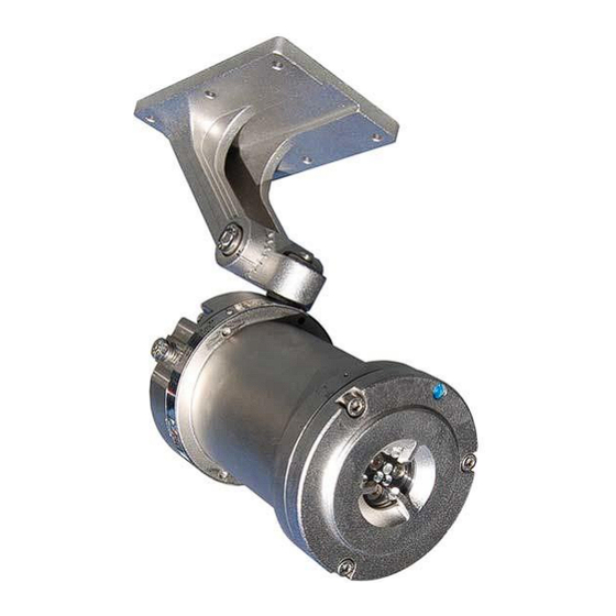
IPES IR3 Flame Detector Operating Manual 5.0 Performance Characteristics Figure 5-1: IPES-IR3 Components Appearance The IPES‐IR3 consists of an explosion‐proof casing with sensors to detect electromagnetic radiation from flames at three points within a spectral window of 4.0 to 5.0μm. Detection is performed using Infrared Sensors that capture heat and radiating gas signatures emitted by fire. -
Page 12: Elimination Of False Alarms
820-0003 IPES IR3 Flame Detector Operating Manual Elimination of False False alarms from detectors used for industrial applications can cost productivity in down time. This is especially noted for Alarms automated systems and processes. Conversely, failure to generate an alarm can have catastrophic results. The combination of microprocessor, algorithms, multiple sensors and wavelength range settings makes the IPES‐IR3 an excellent choice for elimination of false positive indicators caused by non‐flame sources of radiation such as artificial lighting, direct and indirect sunlight, lightning, electrical arcs, radiation (nuclear), arc welding and metal grinding. - Page 13 820-0003 IPES IR3 Flame Detector Operating Manual Table 5‐1: Determining LED Conditions After completing all installation steps, refer to the illustration and LED indicator table below to determine LED conditions. Fire Fault Relay State Relay Status Output Normally open Normally closed signal, IPES‐IR3 status when energized...
-
Page 14: Analog Signal
820-0003 IPES IR3 Flame Detector Operating Manual Analog Signal Analog signal (4‐20 mA) Signal level Detector State (±0.1) mA Circuit opening (2 ± 0.1) mA Fault (4 ± 0.1) mA Normal (18 ± 0.1) mA Fire (2 ± 0.1) mA Magnetic Collar Test (4.1 ±... -
Page 15: Installation
820-0003 IPES IR3 Flame Detector Operating Manual 6.0 Installation Component Parts The IPES‐IR3 detector component parts and delivery set consists of the following: and Delivery Set • One IPES‐IR3 Fire Detector • One Adjustable Mounting Bracket • One Operating Manual •... -
Page 16: Moisture Damage Protection
820-0003 IPES IR3 Flame Detector Operating Manual Moisture Damage Protection • It is the responsibility of the installer to take proper precautions during installation to protect the electrical connections and components from moisture. • Anti‐seize lubricant is provided for easy assembly and corrosion protection of the joints between the enclosure/cover and enclosure/base. -
Page 17: Earth Grounding
820-0003 IPES IR3 Flame Detector Operating Manual Earth Grounding The enclosure of the IPES‐IR3 must be earthed/grounded for electrical safety and to limit the effects of radio frequency interference. An earth/ground point is provided on the outside of the IPES‐IR3 Explosion Proof enclosure. -
Page 18: Ipes-Ir3 Terminal Block
820-0003 IPES IR3 Flame Detector Operating Manual IPES‐IR3 Terminal Block Table 6‐1: Arrangement of Electrical Connections Terminal Block Function +24V 24VDC from system power source (External User Provided) System Ground from system power source (External User Provided) +4/20 Industry Standard +4-20mA current loop output RS485A RS-485 MODBUS RS485B... -
Page 19: Completing The Installation
820-0003 IPES IR3 Flame Detector Operating Manual Completing the Installation For the following, Unscrew the M5 Socket Head Cap screws from the base. Remove the detector from the base. Detach NPT conduit bushing from base. Install the base on a suitable work platform and secure using the 4 mounting screws, washers, nuts, and rubber grommets. -
Page 20: Ipes-Ir3 3 Wire +4 To 20 Ma Current Loop Wiring Diagram
Figure 6-3: IPES-IR3 Connection to Analog +4 to 20 mA Current Loop Connection to Digital RS‐485 Circuit Figure 6-4: IPES-IR3 Connection to Digital RS-485 Circuit... -
Page 21: Startup And Operation
820-0003 IPES IR3 Flame Detector Operating Manual 7.0 Startup and Operation Installation Review Once the mounting, cabling, and alarm relay installation has been completed, the IPES IR3 is ready to begin the Prior to Startup power‐on sequence. Before applying power to the system for the first time, review the steps below: •... -
Page 22: Ipes-Ir3 In Self-Test Mode
820-0003 IPES IR3 Flame Detector Operating Manual IPES‐IR3 in Self‐Test Mode After a successful test, the output signals of the IPES‐IR3 will be in the following states: • Actuation (closure of contacts) of ‘Fault relay, indicating a ‘Working order’/operational condition. •... -
Page 23: Photonic Detector Locations
820-0003 IPES IR3 Flame Detector Operating Manual Photonic Detector Locations Dust/ Obstruction Simulation of dust or obstruction on optical window of the IPES‐IR3 is done by placing a non‐transparent material with Fault Test good reflective properties (white sheet of paper) in front of the optical window of IR channel for 15‐20 sec. If the Dust/obstruction detection function is working properly, the FAULT Relay will activate (Open) and the status LED will alternate YELLOW‐GREEN to indicate the fault. -
Page 24: Troubleshooting
820-0003 IPES IR3 Flame Detector Operating Manual 8.0 Troubleshooting The sensor module (“front” half of the detector) contains no user‐ serviceable components and should never be opened. The terminal compartment is the only part of the enclosure that should be opened by the user in the field. -
Page 25: Maintenance
820-0003 IPES IR3 Flame Detector Operating Manual 9.0 Maintenance Disconnect or power down all output devices and alarms to prevent false actuation. Maintenance IPES‐IR3 maintenance includes the following activities: • Activities Visual examination • Cleaning • Checking the grounding and explosion‐protection systems •... -
Page 26: Automatic Testing
820-0003 IPES IR3 Flame Detector Operating Manual NOTES: • Always make sure that the ITES Test Lamp has fresh batteries. • Keep the Test Lamp lens free from dust, dirt, and moisture. If necessary, clean the lens with a soft wool or cotton cloth. -
Page 27: Warranties
820-0003 IPES IR3 Flame Detector Operating Manual 11.0 Warranties ESP Safety, Inc. (“ESP”) warrants the IPES‐IR3 Flame Detector to be free from defects in material and workmanship under normal use and service for a period of five (5) years, beginning on the date of shipment to the buyer. This warranty extends only to the sale of new and unused products to the original buyer. -
Page 28: Repair And Return
820-0003 IPES IR3 Flame Detector Operating Manual 12.0 Repair and Return Field Repair The IPES‐IR3 detector is not intended to be repaired in the field. If a problem should develop, refer to Section 8.0 Troubleshooting of this manual. If it is determined that the problem is caused by a manufacturing defect, please return the device to the factory for repair or replacement. -
Page 29: Certifications
820-0003 IPES IR3 Flame Detector Operating Manual 14.0 Certifications The IPES–IR3 meets the following certifications: FM (U.S. & Class I, Division 1, Groups B, C & D, Canada) T4, Ta = ‐40 C to +85 C (‐40 F to Hazardous +185 F) IP66 Locations... - Page 30 820-0003 IPES IR3 Flame Detector Operating Manual IEC/IECEx Flameproof “d” Ex d IIC T4 Gb Ta = ‐40 F to +185 F (‐40 C to +85 Supporting Standards: IEC 60079‐0:2007; IEC 60079‐1:2007 IECEx Certificate Number: IECEx FMG 11.0012X Specific Conditions of Use: ISO Class A2‐70, M5 X 16 socket‐head cap screws (Yield Stress 450 MPa) shall be used to replace the cover fasteners.
-
Page 31: Appendix A: Ipes-Ir3 Explosion Protection Means
820-0003 IPES IR3 Flame Detector Operating Manual Appendix A: IPES-IR3 Explosion Protection Means Feature Protection Means Enclosure of Current Carrying Parts The casing includes spigot joints with controlled gaps to meet explosion‐proof requirements for installation in Class I, Division I, Group B, C and D, and T4 locations. -
Page 32: Appendix B: Ipes Digital Communications Protocol
820-0003 IPES IR3 Flame Detector Operating Manual Appendix B: IPES Digital Communications Protocol IPES Commands In addition to supporting analog signals (current loop and relays), IPES‐IR3 flame detectors are also capable of digital communications with remote consoles. IPES‐IR3 detectors use a standard RS‐485 interface with a Modbus RTU protocol layer defining the transactions between the IPES‐IR3 and the console. - Page 33 820-0003 IPES IR3 Flame Detector Operating Manual Poll Status The following 8‐byte Modbus command may be sent in order to poll the status of the IPES‐ IR3: Command 8‐byte Modbus command Byte Description Current Modbus address (247 if IPES‐IR3 set to factory default. 4 (Modbus function code for reading from the device) Low byte of 16‐bit CRC High byte of 16‐bit CRC...
-
Page 34: Appendix C: Hart Communication Protocol
Connect a cable to X3 terminal (+4/20) that is in series with a 250 Ohm resistor. This cable shall then connect to another side of the Field communicator terminal Power up the IR3 and Field communicator. Follow the HART menu tree to navigate to the corresponding function. IPES-IR3 Connection to HART Communicator Handheld Device (3-Wire) Page 34 of 37... - Page 35 The connection shall form a parallel circuit with the 250 Ohm resistor Power up the IR3 and Field communicator. Follow the HART menu to navigate to the corresponding function. IPES-IR3 Connection to HART Communicator Handheld Device (4-Wire) Page 35 of 37...
- Page 36 820-0003 IPES IR3 Flame Detector Operating Manual Page 36 of 37...
- Page 37 820-0003 IPES IR3 Flame Detector Operating Manual Page 37 of 37...
Need help?
Do you have a question about the IPES-IR3 and is the answer not in the manual?
Questions and answers