
Related Manuals for TelePost LP-100A

Summary of Contents for TelePost LP-100A
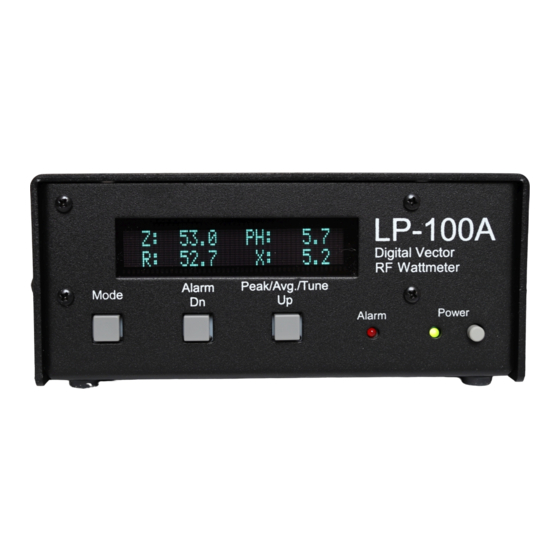
- Page 1 LP-100A Digital Vector RF Wattmeter Operations Manual Covers LP-100A serial numbers starting at 2020, and firmware beginning at v1.2.3.1...
- Page 2 E.I. du Pont de Nemours and Company. PICmicro® is a registered trademark of MicroChip Technology Inc. Material in this document copyrighted © 2013 TelePost Inc. All rights reserved. All firmware and software used in the LP- 100(A), VCP and Plot programs copyrighted © 2004-2013 TelePost Inc. All rights reserved. MicroCode Loader is a...
-
Page 3: Table Of Contents
Operation Overview ....................6 Detailed Operation ....................9 Setup Menus ......................14 Circuit Description ....................16 Schematic .......................18 Software ........................20 Specifications ......................26 Warranty ........................27 Appendix .........................28 Calibration ......................31 Note: Calibration info is provided for reference. LP-100A is factory calibrated with NIST traceable instruments. -
Page 4: Introduction
Conforms to FCC Part 15 A & B, ICAS and CE radiated emission limits, tested and verified by accredited lab This manual will address the operation of the LP-100A. For those who are interested, there is also a section on Calibration, even though this is already done at the factory. -
Page 5: Connections
Power: 11-16 VDC @ 330 mA max., center pin +, 2.5mm ID. The lead with the white stripe on the supplied cable is + PTT: Loop the PTT (amp keying) between your amplifier and rig through the LP-100A using RCA connectors RS-232: Connects to computer…... -
Page 6: Operation Overview
Operation Overview Operation of the LP-100A is straightforward, and designed to require a minimum of input. There are only three buttons which are used in combination to access all the menus on the LP-100A. There are five main modes for the LP-100A, which are accessed by momentarily pressing the “Mode”... - Page 7 SSB operating. Note: The Peak Mode is VERY fast, and can respond to a lip smack, mic button click, etc. Don’t be alarmed by this… it is normal, and allows the LP-100A to provide an accurate indication of peak power. Unless a lot of compression is used, the peak reading will occasionally be somewhat higher than the indication with a carrier…...
- Page 8 ALC timing characteristics of modern rigs in both CW and SSB. The peak detector in the LP-100A is very fast, and will grab even the smallest peak. Peak SWR will show values a little higher than steady-state at times due to the wide dynamic range of the LP-100A.
-
Page 9: Detailed Operation
It is also very useful for doing antenna field strength measurements, as in checking a beam pattern. This requires feeding a small pickup antenna to one of the inputs. The LP-100A could be set up in a field, connected to a laptop computer with wi-fi, and the results can be read over the wireless LAN back in the shack. - Page 10 Peak is best for CW or SSB operating. Note: The Peak Mode is VERY fast, and can respond to a lip smack, mic button click, etc. Don’t be alarmed by this… it is normal, and allows the LP-100A to provide an accurate indication of peak power.
- Page 11 You can use any brightness level you like. The display is rated for 50,000 hours (5.7 years) of continuous display at full brightness before brightness drops to half. With the LP-100A’s screen savers, you can expect much more than that with typical operating habits.
- Page 12 For amplifier tuning, you should switch to Tune mode for fast update of both bargraph and numerical readout. The bargraph sampling in the LP-100A is about 60 samples/second, and it will display a single dit at 100 wpm, or a string of pulses as with a pulser or keyer set for high speed.
- Page 13 Similar to dBm mode except that it is calibrated to display power from –15 dBm to +33 dBm. There is no return loss in this mode because it does not utilize the coupler. Power is supplied directly to either one of the inputs on the back of the LP-100A. This mode can be used for accurate low power bench measurements, as in checking the output to a transverter or the level of a local oscillator or mixer.
-
Page 14: Setup Menus
Deg F & C. The Dn button resets the microprocessor, and is useful when flash updating the firmware in the LP-100A. The Up button toggles the temperature mode. This screen is used to set the “User” SWR Alarm setpoint. It can be set between 1.0 and 5.0 in steps of 0.1. - Page 15 50,000 hours (5.7 years) of continuous display at full brightness before brightness drops to half. With the LP-100A’s screen savers, you can expect much more than that with typical operating habits. Use Dn to reduce brightness, Up to increase. The brightness of the screen changes as you adjust it.
-
Page 16: Circuit Description
Screen Saver The screen saver works a little differently than it did in the LP-100A due to the different requirements of the GVFD display. It is a three- step process. The first step only works in the Normal mode, while the other two work in all modes and screens. Step 1 is to dim the display to 25% when in Normal mode. - Page 17 MicroCode Loader (MCLoader), from Mecanique®, is provided to do this. A Windows® charting program is also provided to allow graphing of any of the LP-100A’s parameters including Z, R, X, SWR and phase angle vs. frequency. The Plot program also offers a Smith Chart display, and I plan to add a translation function to allow for automatic transformation of coupler load Z to antenna feedpoint Z.
-
Page 18: Schematic
Schematic Page 1... - Page 19 Schematic Page 2 Coupler Schematic...
-
Page 20: Software
$18, model USB-COM-CBL. Drivers for almost any platform should be downloadable from FTDI. I have been asked about a USB port for the LP-100A, and it would be easy to do, but since all ham software has native RS-232 com support, and older machines don’t have USB ports, I think a RS-232 port with an inexpensive USB adapter where needed is the most flexible choice. - Page 21 Note: It is important to open the file you want each time you launch MCLoader, or else it will start up with the last used file, and you may forget to open a new file and reprogram your LP-100A with an older version. It is even possible that you might have a file from another device loaded, since MCLoader is used by other manufacturers as well.
- Page 22 Plot version 1.01 is available for download on the LP-100A Current Software page at http://www.telepostinc.com/LP-100A-Update.html. The Plot program is designed to interface between your rig and the LP-100A Digital vector Wattmeter, to enable scanning of antennas or other loads and displaying performance parameters versus frequency.
- Page 23 When you first launch Plot, you should see something similar to the above, although the default display is R+jX. If you don't see the setup info at the bottom, select Diag in the Setup menu. Select the LP-100A com port number in the far left com port selector, and the firmware range of your LP-100A firmware.
- Page 24 Software Cont’d SaveAs/Export/Print Dialog This screen is accessed under the File menu. It allows saving and printing of the plot results in a variety of formats. The basic procedure for its use is to select the file type at the top, select a destination and size, and then click export. If you select Text/Data and File as the destination, a standard Windows explorer type file dialog will appear, where you can navigate to the folder you want and name a file, etc.
- Page 25 I will not go into detail here on the use of PolarPlot, but I will briefly discuss the basic operation as it pertains to the LP-100A. The basic setup would be to set the LP-100A up for operation in Field Strength mode (sampling antenna plugged into one of the ports on the back of the main LP-100A chassis).
-
Page 26: Specifications
Master Power Trim Gain Slope Trim Phase Slope Trim Lo/Hi Power Trim Frequency Counter Trim Log the initial CAL constants for your LP-100A in this table. If you ever make changes, you can log additional constants in the spaces provided. -
Page 27: Warranty
Repaired or replaced items are warranted for the remainder of the original warranty period. You may be charged for repair or replacement of the LP-100A made after the expiration of the warranty period at our discretion or where, in our reasonable opinion, the damage is due to abuse, accident, improper or abnormal usage, improper installation, alteration, lightning or other incidence of excessive voltage or current. - Page 28 The LP-100A is designed to work with a 50 ohm source impedance. When an internal antenna tuner is used, the output impedance of the rig will no longer be 50 ohms. You will also experience a power loss in the tuner of up to 20% or so, which will be seen on the LP-100A. To measure an antenna’s actual impedance requires that any internal tuner be bypassed, as well as any external tuner which follows the LP-100A.
-
Page 29: Appendix
A peak diode detector rectifies the RF envelope and charges a small filter cap to the peak voltage level of the applied signal. The response time of the detector is determined by the time constant of the cap and load resistance. In the case of the LP-100A, this time is very small. To obtain a true “average”... - Page 30 This is relatively easy if you are generating the signal internally, but in the case of the LP-100A, the source is a high power signal out of the control of the LP-100A. I have developed a circuit for sign detection, but it would require a rather substantial change to the PCB. I may change to it in the future, but it wouldn’t be for quite awhile.
-
Page 31: Calibration
This adjustment is used to calibrate the slope of the phase detector. It is simply done by inserting a line with known delay into the Current input of the LP-100A, and transmitting into a high quality 50 ohm dummy load. - Page 32 Also check the maximum power range selected in the Setup screens.. It also sets the maximum power to match your coupler. There are six couplers currently available for the LP-100A, with more to come.
- Page 33 Fine trims, it is necessary to provide an accurate means of measuring power that is independent of the LP-100A. The simplest approach to this is to borrow a high quality meter like a Bird or Alpha to use as a reference, and connect it between the LP-100A and dummy load with a UHF male-male adapter.
- Page 34 The actual diode drop will very likely be within about .2V of the assumed value in the formula, for a voltage error of under 2%. If you don’t have access to these methods, you can send your completed LP-100A back to me for calibration if you are willing to pay for return shipping costs.
Need help?
Do you have a question about the LP-100A and is the answer not in the manual?
Questions and answers