Table of Contents
Advertisement
Advertisement
Table of Contents

Related Manuals for De La Rue talaris Multimech

Summary of Contents for De La Rue talaris Multimech
- Page 1 Multimech Integration manual Doc. No. 8030974/01-en-GB Date: 2011-03-16...
- Page 2 This page is intentionally left blank...
-
Page 3: Obligations Of The User
Obligations of the user Obligations of the user • Everyone working with the machine must read this manual. • Observe the safety instructions and warning labels. • Talaris or its representative should replace damaged safety devices such as fuses and warning labels immediately. -
Page 4: Preface
Preface Preface MultiMech is the name of the Talaris Dispenser for ATM use. This manual comprises instructions for installation of the Multimech • data for preparation of the site • Instructions for installation • Instructions for operating the Multimech Talaris Cash Dispensing AB Flen, SWEDEN Doc. -
Page 5: Table Of Contents
Contents Contents Contents Obligations of the user ..............3 Preface.................... 4 Presentation ..................6 MultiMech ................. 6 General ................... 7 General..................7 Specifications................... 9 Power supply................9 Weight ..................9 Climatic requirements ..............10 Relative humidity ............... 10 Site preparation................11 Dimensions ................ -
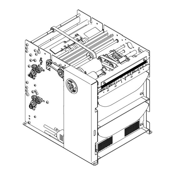
Page 6: Presentation
Presentation Presentation MultiMech Machine overview Fig. 1 MultiMech Description Note qualifier PC—Board MultiMech Quick fill cassette QF020 Quick fill reject QFR010 Note outlet Note transport Doc. No. 8030974/01-en-GB... -
Page 7: General
General General General This section describes different alternatives of installation and other general requirements. When planning the MultiMech installation, the following "four modes of operation" must be considered: • Under normal operation the transport of notes through the delivery slot is controlled by the host computer. - Page 8 General Safety and EMC requirements The system manufacturer is responsible for making sure that the appropriate safety and EMC requirements are used. Assembling the MultiMech in a cabinet. When assembling the MultiMech into a cabinet, we recommend the use of the four holes as shown in diagram to firmly attach the MultiMech into the cabinet.
-
Page 9: Specifications
Specifications Specifications Power supply The MultiMech requirements and recommendations for an external power supply are as follows: Input Connector The AC-mains connector is recommended to be IEC-320 style. DC output voltage +24.0 V 10% SELV output and Limited Power Source Load current, continuous Min 0.2 A Max 2.5 A... -
Page 10: Climatic Requirements
Specifications Climatic requirements Operating +5 to +50 °C / +41 to +122 °F Storage -5 to +60 °C / +23 to +140 °F Transport 40 to +70 °C / -40 to +158 °F Note: The transport temperature is valid for 72 hrs. maximum. Relative humidity Operating 10 to 85%... -
Page 11: Site Preparation
Site preparation Site preparation Dimensions All dimensions in (mm) Doc. No. 8030974/01-en-GB... - Page 12 Site preparation Doc. No. 8030974/01-en-GB...
-
Page 13: Delivery Slot Dimensions
Site preparation Delivery slot dimensions It is important when integrating the MultiMech into a cabinet that the delivery slot of the MultiMech is correctly aligned with the slot in the cabinet. If the MultiMech is moved out from and into the cabinet e.g. -
Page 14: Note And Reject Cassette Qfr010 And Qfr020
Site preparation Note and reject cassette QFR010 and QFR020 Note and reject cassette QFR010 and QF020 Fig. 2 Quick fill cassette QF020 Fig. 3 Quick fill reject cassette QF010 Doc. No. 8030974/01-en-GB... -
Page 15: Required Space Upon Service And Maintenance
Site preparation Required space upon service and maintenance For refilling • The space in front of the MultiMech is required for removing and inserting the note compartment. For operator maintenance • The space in front of the MultiMech is required for removing and inserting the note compartment. - Page 16 Site preparation For service and maintenance • The space around the MultiMech is required for commissioning of the MultiMech. Doc. No. 8030974/01-en-GB...
-
Page 17: Connections
Site preparation Connections Note: Never connect the machine to anything else then +24 V +-10%. The power supply (Talaris or the ATM-ps) must be switched off when the power connector of the MMC is fitted. ATTENTION Internal inter module connections and signal connections in modules must not be touched without measures taken for ESD protection. -
Page 18: Communication Cable Specifications
Site preparation Communication cable specifications (For Talaris standard cables, made for PC) Fig. 4 Without handshaking (shield connected to connector housing) Fig. 5 With handshaking (shield connected to connector housing) Connector, CT 5-pol, AMP 173 977 - 5 Connector, D-SUB 9-pol, AMP 748 047 - 1, shielded Cable, AWG26*6, shielded Doc. - Page 19 Site preparation Connect to MultiMech USB port type B receptacle Connect to PC USB port type A receptacle Connect to MultiMech RS232C DSUB9 Receptable Connect to PC RS232C DSUB9 plug Doc. No. 8030974/01-en-GB...
-
Page 20: Operating The Multimech
Operating the MultiMech Operating the MultiMech 1. Run program NMD-test 2. Choose set up/Communiaction Choose Com Port and Handshake. Make sure that Parity is set to Even. Baudrate is always set to 9600. 3. Choose Info/statistics Choose Open cassette and Read Cassette ID The NMD test menu shows a number of commands, for detailed description please refer to the Communication and Command Reference... - Page 21 Operating the MultiMech 4. To operate the MultiMech normally only the five following commands are needed. (0) Reset (2) Move Forward (5) Read Cassette ID (7) Close Cassette (8) Open Cassette Operating sequence 1. The operating sequence is as follows (0) Reset (1) Open Cassette (2) Read Cassette...
-
Page 22: Qfr 010/ Qf 020
QFR 010/ QF 020 QFR 010/ QF 020 Removal of note guides The following instructions apply to both cassettes 1. Loosen and remove three screws on each side of the cassette according to the illustration. Doc. No. 8030974/01-en-GB... - Page 23 QFR 010/ QF 020 2. Pull the reject box slightly backwards according to the illustration. 3. Lift out the guides as shown Doc. No. 8030974/01-en-GB...
-
Page 24: Refit The Note Guides
QFR 010/ QF 020 Refit the note guides 1. Refit the note guides according to note tables. Use the marked pins as a reference when refitting the guides into the matrix. 2. Push reject box back into place and tighten the six screws. -
Page 25: Note Table
QFR 010/ QF 020 Note table 1. Follow the table for note width and note length to see in which position to fit the note guides. Tables for adjustment Note height (mm) Adjustment From Position Doc. No. 8030974/01-en-GB... - Page 26 QFR 010/ QF 020 Note height (mm) Adjustment From Position left Position right Doc. No. 8030974/01-en-GB...
-
Page 27: Safety Requirements
Safety requirements Safety requirements External interconnection Interconnecting cables and cable assemblies used for external interconnection between parts of equipment or between components. Chassis GND The machine chassis needs to be connected to GND due to EMC levels. The GND connection can be made either on one of the six fastening points on the bottom plate or with a separate cable from the connector on the sideplate. - Page 28 lastpage The Talaris Commitment Talaris are World Experts in cash management. Across the globe 2,300 personnel, with over 130 business partners deliver technology and solutions that provide security, productivity and innovation to our customers. The company is committed to the highest ethical standards and compliance with legislation and to be a fair employer wherever we operate.
Need help?
Do you have a question about the talaris Multimech and is the answer not in the manual?
Questions and answers