
Summary of Contents for Peak PLIN-LWL
- Page 1 PLIN-LWL Optical Coupler for LIN Data Transmission User Manual Document version 1.2.0 (2019-03-14)
- Page 2 Copyright © 2019 PEAK-System Technik GmbH Duplication (copying, printing, or other forms) and the electronic distribution of this document is only allowed with explicit permission of PEAK-System Technik GmbH. PEAK-System Technik GmbH reserves the right to change technical data without prior announcement.
-
Page 3: Table Of Contents
PLIN-LWL – User Manual Contents Introduction Properties at a Glance Operation Requirements Scope of Supply Connectors Optical Waveguides (OWG) Voltage Supply Configuration Configuration LIN Transceiver Configuration Power Supply Configuration Internal Supply LIN Master Termination Operation LIN Transmission Rate Status LEDs... -
Page 4: Introduction
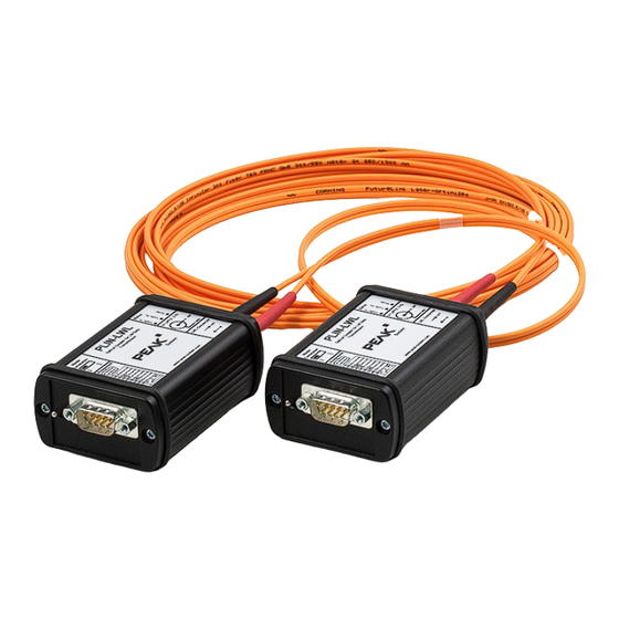
PLIN-LWL – User Manual Introduction For use in explosion-proof areas or for EMC measurements, the PLIN-LWL can be used to replace a stretch of LIN network with a fiber-optic line at any point. The modules are supplied with power externally. -
Page 5: Operation Requirements
Operation Requirements LIN network (Master or Slave termination can be selected per module) D-Sub sockets for connection to the PLIN-LWL modules Power supply with power supply unit or via the D-Sub connector Scope of Supply 2 PLIN-LWL modules including power supply units A choice of 5 or 10 m FO cable, 62.5/125 μm duplex line ST... -
Page 6: Connectors
The LIN bus is connected to the 9-pin D-Sub connector on the left casing side. Figure 2: Pin assignment D-Sub connector Pin 9 can be used to supply a PLIN-LWL module. See section 3.2 Configuration Power Supply on page 11 for further information. -
Page 7: Optical Waveguides (Owg)
PLIN-LWL – User Manual Optical Waveguides (OWG) Figure 3: Casing side with OWG connectors, voltage socket, and LEDs A PLIN-LWL module has two standardized ST connectors for the optical waveguides. The connections are separately in charge of sending and receiving light signals. -
Page 8: Voltage Supply
PLIN-LWL – User Manual Voltage Supply A PLIN-LWL module needs a DC voltage of 8 to 30 V. At the voltage input socket you can connect the supplied 12-Volt power supply unit. Figure 4: Figure 5: Assignment voltage input socket Diameter barrel connector: a = 5.5 mm, b = 2.1 mm... -
Page 9: Configuration
PLIN-LWL – User Manual Configuration At the PLIN-LWL housing, a termination for the Master operation mode can be switched on with a toggle switch. On the circuit board of the module, you can do the following jumper settings affecting the basic operation:... -
Page 10: Configuration Lin Transceiver
Figure 6: Position of the jumper blocks JP3 and JP7 Transceiver Jumper setting Comment JP3 and JP7 Low-speed (/10) High-speed (/20) Default setting at delivery Tipp: Both PLIN-LWL modules being connected with each other can use different LIN transceiver settings. -
Page 11: Configuration Power Supply
PLIN-LWL – User Manual Configuration Power Supply A PLIN-LWL module can be supplied either by an external voltage source (e.g. the supplied power supply unit) via the corresponding input socket or via pin 9 of the D-Sub connector (in each case 8 - 30 V DC). - Page 12 Attention! Switch off the power supply at the D-Sub connector before connecting or removing the D-Sub plug to or from the PLIN-LWL module. Otherwise electronic parts may be des- troyed, even on other nodes attached to the LIN bus.
-
Page 13: Configuration Internal Supply
PLIN-LWL – User Manual Configuration Internal Supply The PLIN-LWL has a linear and a switching regulator for generating the internal 5-volt supply. The jumpers JP8 and JP9 determine which voltage transformer is used. Switching regulators can cause unwanted oscillations. Linear... -
Page 14: Lin Master Termination
PLIN-LWL – User Manual LIN Master Termination The PLIN-LWL can be operated in a LIN bus as Master or Slave. If using as Master, the toggle switch at the left side must be set to the lower position. This enables a termination of 1 k which enhances the level and the flanks of the transmitted signal. -
Page 15: Operation
PLIN-LWL – User Manual Operation LIN Transmission Rate When operating the PLIN-LWL modules, it must be ensured that the transmission rate of all participants connected to the LIN bus is identical. There is no conversion or automatic adaptation of the bit rate. -
Page 16: Technical Specifications
PLIN-LWL – User Manual Technical Specifications High-speed LIN D-Sub male connector, 9-pin Transceiver: TJA1028T/5V0/20 Bit rates: 2.4 - 20 kbit/s Low-speed LIN D-Sub male connector, 9-pin Transceiver: TJA1028T/5V0/10 Bit rates: 2.4 – 10.4 kbit/s Optical waveguide Fiber optic duplex line with ST connector... -
Page 17: Appendix Ace Certificate
PLIN-LWL – User Manual Appendix A CE Certificate... -
Page 18: Appendix B Emission Diagram
PLIN-LWL – User Manual Appendix B Emission Diagram Figure 11: Emission with and without PLIN-LWL... -
Page 19: Appendix C Dimension Drawing
PLIN-LWL – User Manual Appendix C Dimension Drawing Figure 12: Dimension drawing of the PLIN-LWL The figure does not show the original size.
Need help?
Do you have a question about the PLIN-LWL and is the answer not in the manual?
Questions and answers