Table of Contents
Advertisement
Quick Links
LR-J1900T V1.13 Manual
Motherboard Specification:
Motherboard Size
Processor
RAM
Expansion BUS
Rear I/O
Internal I/O
BIOS
Network
Audio
Power Supply
Environment
Operating system
- ITX170mmX170mm
- Intel® J1900 CPU
- 1*204PinDDR3L SO-DIMMSlot
- support 1.35V/ DDR3L memory, up to 8G
- 1 x M.2 slot, support WIFI
- 1 x MINI_SATA slot, supportSSD
- 1 x DCINPort
- 1 x LAN Port/2 x USB 2.0
- 1 x LAN Port
- 1 x VGAPort
- 1 x USB 2.0Port
- 1 x USB 3.0 Port
- 1 x HDMI Ports
- 1 x LineOut(Green)
- 1 x MIC-IN(Red)
- 1 x 4Pin ATX Pins
- 1 x F_PANEL
- 2 x Fan Pins(CPU_FAN/SYS_FAN)
- 2 x F_USB2.0 Pins,supports 4 x USB2.0
- 1 x FUSB2.0 Pin,support 1x USB2.0
- 1 x F_AUDIO1
- 1 x SPKERS1
- 1 x SATA1
- 1 x JPWR_SATA
- 1 x LVDS_CON1
- 1 x INV_VOT1
- 6 xCOM Pins
- 1 x J_LPT1
- 1 x VGA_F1
- 1 x JHD
- 1 x JCMOS(Default 1-2pin)
- 1 x AUTO_ON (Default 1-2pin)
- 1 x COM1_SET(Default 3-4pin)
- 1 x COM2_SET(Default 3-4pin)
- 1 x J485
- 1 x GPIO
- AMIBIOS
- Integrated 10/100/1000Mbps Gigabit Ethernet
-Realtek ALC662
- 4PIN ATX or 12VDC
- Operating Temp.:-10 ℃~50℃
- Operating Humidity:0%~95%
Windows 7 /Windows 8 /Windows 8.1 /Windows10/Linux
Advertisement
Table of Contents

Related Manuals for Realan LR-J1900T


Summary of Contents for Realan LR-J1900T
- Page 1 LR-J1900T V1.13 Manual Motherboard Specification: Motherboard Size - ITX170mmX170mm - Intel® J1900 CPU Processor - 1*204PinDDR3L SO-DIMMSlot - support 1.35V/ DDR3L memory, up to 8G Expansion BUS - 1 x M.2 slot, support WIFI - 1 x MINI_SATA slot, supportSSD - 1 x DCINPort - 1 x LAN Port/2 x USB 2.0...
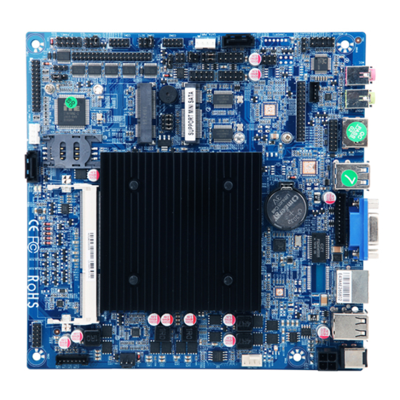
- Page 2 MB Layout GPIO COM6 COM5 COM4 COM3 COM2 COM1 COM1_SET COM2_SET1 AUTO_ON J_LPT LVDS_PWR J485_422 COM2_SET2 LR_J1900T V1.13 F_USB SPKERS1 FP_AUDIO LCD_SET HDD_PWR F_USB2 CPU_FAN2 CPU_FAN3 SATA1 F_USB1...
-
Page 3: Installation Instructions
Installation Instructions Tips: Please don’t remove or damage the QC labelon the board • • Make sure the power off before starting installation or remove motherboard and others hardwares • Hold the board by edges,please don’t touch any components or pin of plug &socket. - Page 4 2.1 ATX12Power Board provide 1*4Pin ATX power connector, support 12V input/output ATX_12V GND2 12V2 GND1 12V1 PWR_4P 2.2 Display Port (VGA_F1) Board provide 1*12 Pin VGA _F1 connector (Pitch:2.0mm), definition as follow: VGA_F1 Signal Name Signal Name VGA_VSYNC VGA_HSYNC VGA_RED(ReD) VGA_GRN(Green)...
-
Page 5: Audio Port
2.6 J H D definition: HDMI Board provide 1*2x8pinHDMIport (Pitch2.0mm), definition as follow Signal Name Signal Name HDMI_TXD2_P HDMI_DDC_CLK_R HDMI_TXD2_N HDMI_DDC_DATA_R HDMI_TXD1_P HDMI_TXD1_N HPD_CONN HDMI_TXD0_P +5V_HDMI HDMI_TXD0_N HDMI_TXC0P HDMI_TXC0N 2.7 Parallel port :J_LPT definition Board provide 2*13Pinprint port (Pitch:2.00mm),definition as follow J_LPT Signal Name Signal Name... -
Page 6: Clear Cmosjumper:jcmos
2.10 USB Port:F_USB1、F_USB2 Board provide 2* standard USB2.0 Ports 2*5pin(Pitch: 2.54mm).definition as follow F_USB1/F_USB2 Signal Name Signal Name VCC+5V VCC+5V USB1Date- USB2Date- USB1Date+ USB2Date+ 2X5NC9 2.11 front panel port:F_PANEL Board provide 1*2x 5PinFront Panel port (Pitch:2.54mm), definition as follow: F_PANEL Signal Name Signal Name HDDLED+... -
Page 7: Serial Ports: Com1、Com2、Com3、Com4、Com5、Com6
2.15 LVDSPower Jumper:LVDS_PWR Board provide1*2x3pinLCD_SETconnector, (Pitch:2.54mm), definition as follow: Signal Name LVDS_PWR +3.3V +12V 2.16 Auto On Funtion:AUTO_ON Board provide1*1x3Pinconnector (Pitch:2.54mm),definition as follow: AUTO_ON Signal Name 1-2(Default) Normal Auto Power on 2.17 Jumper for LCD Resolution:LCD_SEL Board provide4*1x2Pinconnector (Pitch:2.54mm,definition as follow: LCD_SEL 1024X768X6 LCD_SEL... - Page 8 Board provide 6* RS232 serial ports, 2*5Pin(Pitch=2.0mm) COM1 Signal Name Signal Name NDCD NSIN NDTR NSOUT NDSR NCTS NRTS 2.18.1 COM Power Jumper:COM1_SET/COM2_SET1 Board provide1*2x3pinCOM_SET connector,adjust power supply by COM1/COM2 (Pitch:2.54mm),definition as follow: Signal Name COM_SET +12V +DCD 2.18.2 RS232/RS422/RS485 Jumper:COM_SET2 Board provide 1*2x3pinCOM_SET2 connector,for adjust signal between RS232/ RS422/RS485 (Pitch:2.54mm),definition as follow:...
Need help?
Do you have a question about the LR-J1900T and is the answer not in the manual?
Questions and answers
**** cuánto se alimenta por el puerto DC IN
The Realan LR-J1900T motherboard has a DC IN port for power input, but the specific voltage requirement is not mentioned in the provided information.
This answer is automatically generated