
Related Manuals for HIGHLEAD GC1918 -MDZ


Summary of Contents for HIGHLEAD GC1918 -MDZ
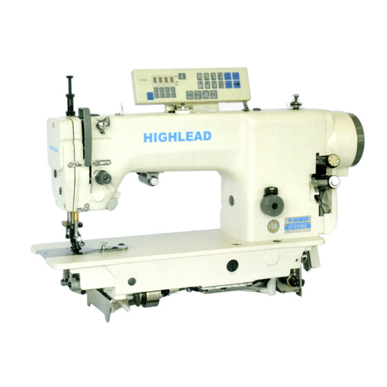
- Page 1 GC1918 -MDZ Direct Drive Semi-Dry Top Variable Feed Lockstitcher With Auto Thread Trimmer Instruction Manual Parts Catalog SHANGHAI BIAOZHUN HAILING SEWING MACHINERY CO., LTD.
-
Page 2: Table Of Contents
----- CONTENTS ----- 1. PRECAUTIONS BEFORE STARTING OPERATION ··················································· 1 Safety precautions ············································································································· 1 Precaution before Starting Operation ··········································································· 1 Precaution for Operating Conditions ············································································ 1 2. SPECIFICATIONS ················································································································· 1 3. PREPARETION BEFORE STARTING OPERATION···················································· 2 Adjustment of needle bar stop position ··············································································· 2 4. - Page 3 Adjustment of clearance between top feed dog and presser foot ···························· 13 Adjustment of vertical motion for top feed dog ························································· 14 Adjustment of top feed arm and top feed lever ························································· 15 Intermittent ruffling unit use ························································································ 16 PARTS CATALOG Arm bed &...
-
Page 4: Precautions Before Starting Operation
PRECAUTIONS BEFORE STARTING OPERATION Safety precautions (1) When turning the power on, keep your hands and fingers away from the area around/under the needle and the area around the pulley. (2) Power must be turned off when the machine is not used,. (3) The power must be turned off before tilting the machine head, installing or adjusting the machine, or when replacing. -
Page 5: Preparetion Before Starting Operation
PREPARETION BEFORE START TO OPERATE Adjustment of needle bar stop position Adjust of "UP" position When the pedal is kicked down by heel, the machine stops at "UP" position. If the marks deviate larger than 3mm adjust as follows. Loosen the screw1 and 2. Run the machine and stop at "UP"... -
Page 6: Adjustment For Amount Of Oil For Hook
Oiling 15 to 20 drops once a week. 2) Adjustment of the amount of oil for hook turn the oil level adjustment screw, and adjust amount of oil for hook.. 3) Periodical cleaning a. Machine (1) Remove the throat plate and clean the feed dog. (2) Assembling is to be made by screwing in the screw by 2 to 3rotations by hand at first, then tightening them evenly by use of a long size... -
Page 7: How To Use The Machine
HOW TO USE THE MACHINE How to attach needle Note: Before making the following adjustment, be sure to switch off the power source. Insert the needle up to the bottom of needle clamp and tighten the screw keeping the long groove side of needle forward the left.... -
Page 8: Adjustment Of The Thread Guide
(3)Touchback switch a. With the push-button (touchback switch) pressed lightly during sewing, reverse sewing can be done. Reverse sewing will take place while the push-button is pressed. When the push-button is released, reverse sewing turns into forward sewing. b. When the push-button is turned 180 degrees in the direction of the arrow, the switch will be locked, and backward sewing will not take place even if the button is pressed. -
Page 9: Adjustment Of Upper Thread Tension
6) Adjusting of upper thread tension (1) Upper thread tension can be adjusted by thread tension nut. (2) Upper thread is to be adjusted according to the lower thread tension. (3) For special fabric sewing with special thread, the desired tension can be obtained by adjusting the strength and operating range of thread take-up spring. -
Page 10: How To Wind The Lower Thread On The Bobbin
9) How to wind the lower thread on the bobbin (1) Press the bobbin onto the thread winding shaft. (2) Pass the thread for winding thread as shown in the figure, and wind the end of the thread clockwise around the bobbin several times, then wind the thread on the thread adjuster side counter-clock wise several times. -
Page 11: Adjustment Of Feed Timing
Adjustment of feed timing (1) Adjust by changing the position of the vertical feed eccentric ring. (2) As a standard, the vertical feed timing Is set to when the screw ① on the bearing bushing is linear with screw ②on the vertical feed eccentric ring. When the eccentric ring is moved in the direction of a, the vertical feed dog will rise earlier. -
Page 12: Adjustment Of Top Feeding
(4) Adjust by adjusting the installation of the fixed knife. Knife engagement amount (1) When the sewing machine is rotated while the solenoid is activated, the knife (left) will be rotated by the thread trimming cam. As a standard, the knife engagement amount should be 1.5 to 2.0mm when the knife (left) moves the most. -
Page 13: Adjustment Of Sewing Shift
Set the top feeding dial to 3 or more. Turn the intermittent ruffling stopper dial clockwise fully. The position, such as the dial strikes and does not turns any more, is “MAX.” position. (The scale "8" comes just above.) Reset the top feeding dial to the desired scale. Adjustment of sewing shift In case of the lower cloth longer at the sewing end: Adjust the sewing shift by turning the top feeding dial... -
Page 14: Presser Adjustment Of Top Feed Dog
17) Presser adjustment of top feed dog Press down the top feed adjusting knob. The presser to the top feed dog will become stronger when turning . the knob clockwise, and weaker when turning counter-clockwise. (Rotate the top feed presser adjusting knob in such condition as engaged firmly, after depressing downward.) The height A is approx. -
Page 15: Gauge Installation
When fasten the screw A of the presser bar base, adjust the clearance B between the feed rocker bar bushing and the presser bar base evenly and set the presser foot in proper condition that the needle position is on the center line of the slot of the presser foot. -
Page 16: Adjustment Of Upper Horizontal Forked Arm
Adjustment of upper horizontal forked arm Set the drop feed dial to "3", and the intermittent ruffling stopper dial and the Top feeding dial to MAX. (8), respectively. The clearance A between the upper horizontal forked arm and the arm (the side cover attaching surface) is to be adjusted to approx. -
Page 17: Adjustment Of Vertical Motion For Top Feed Dog
Remove the side cover from the back side of the arm. Loosen the setscrew C on the upper horizontal arm. Move the top feed dog, so that the dimension A (in case of the pusher type gauge) or the dimension B (in case of the puller type gauge) becomes 1.0 mm. -
Page 18: Adjustment Of Top Feed Arm And Top Feed Lever
Remove the side cover from the back .side of the arm. Set the horizontal feeding amount of the top feed dog to approx. 3 mm. Set the top feed dog at the most highest position by turning the pulley. Loosen the setscrew A on the top feed vertical arm. Adjust the rising dimension D with the roller B on the top feed vertical arm pushing the bell crank C, so that it becomes the dimensions as follows:... -
Page 19: Intermittent Ruffling Unit Use
25) Intermittent ruffling unit operating method Operating method When it comes to the position to make the ruffle sewing, the ruffling sewing can be done by operating Pneumatic Button 1. As the pedal is reverted, it returns to the ordinary sewing. Adjustment of ruffling amount Press Pneumatic Button 1 and confirm the top feeding indicator 4 moves. -
Page 20: Arm Bed & Its Accessories
A.ARM BED AND IT'S ACCESSORIES ─ 17 ─... - Page 21 A.ARM BED AND IT'S ACCESSORIES Fig. Part No. Description Remarks Pcs. HB2252N072 Bobbin winder base H6723N8001 Cam shaft H6722N8001 Wash H007013050 E-type stop ring HA100H2150 Screw H6721N8001 Adjust plate H3200B2100 Screw H6720N8001 Spanner H6717N8001 Seat H6716N8001 Shaft H6715N8001 Spring H6724N8001 Spring H6710N7101 Winch...
- Page 22 A.ARM BED AND IT'S ACCESSORIES Fig. Part No. Description Remarks Pcs. HA112B0693 Thread tension discs HA710B0673 Screw HA710B0674 Thread guide H6764B7101 Screw assy H6766B8001 O-ring H8810P8001 Screw H8812P8001 Washer HA300B2160 Screw HA100B2110 Screw H6720I8001 Thread take-up cover HA100B2140 Thread guide HA106B0676 Screw HA300B2080...
-
Page 23: Needle Bar And Thread Take-Up Mechanism
B.NEEDLE BAR AND THREAD TAKE-UP MECHANISM ─ 20 ─... - Page 24 B.NEEDLE BAR AND THREAD TAKE-UP MECHANISM Fig. Part No. Description Remarks Pcs. HM00C48001 Upper shaft HM00C68001 Crank HA100C2070 Screw HA307C0662 Screw HA100C2060 Screw H3208H0661 Ball bearing H6711C8001 Bushing H431060080 Screw H6713C8001 Bobbin winder driving wheel H431060080 Screw H6717C8001 Bushing H3205J0662 Ball bearing H6708C8001 Belt pulley (upper)
- Page 25 B.NEEDLE BAR AND THREAD TAKE-UP MECHANISM Fig. Part No. Description Pcs. Remarks H24211D305 Plug HA100C2020 Screw H6716I8001 Thread take-up support shaft H6717I8001 Bearing H6718I8001 Bearing support H6719I8001 Thrust collar HA100B2110 Screw H6706H8001 Square block HA300B2090 Rubber plug H6711B8001 Needle bar bushing(upper) H2504D0653 Screw HM00H88001...
-
Page 26: Feeding And Feed Lifting Mechanism
C.FEEDING AND FEED LIFTING MECHANISM ─ 23 ─... - Page 27 C.FEEDING AND FEED LIFTING MECHANISM Fig. Part No. Description Remarks Pcs. H007009100 Retaining ring-C type H9113D8001 Shaft H9115D8001 Guide crank HA300B2160 Screw HA100C2020 Screw H9116D8001 Eccentric shaft HA106B0676 Screw H9110D8001 Thrust collar H9116E8001 Link H431050050 Screw H9109D8001 Feed lifting connecting rod H6724D8001 Connecting stud H9108D8001...
- Page 28 C.FEEDING AND FEED LIFTING MECHANISM Fig. Part No. Description Remarks Pcs. HA100E2180 Bobbin HA708E0068 Bobbin case assy. H6709D8001 Gear(small) H8832B8001 Lower shaft bushing(right) H6747B8001 Oil seal H6707F8001 Ball bearing H6708F8001 Bushing HA300B2130 Screw HA710E0691 Thread trimmer cam HA710E0692 Screw H8804F8001 Lower shaft H6712F8001 Oil wick...
-
Page 29: Stitch Regulator Mechanism
D.STITCH REGULATOR MECHANISM ─ 26 ─... - Page 30 D.STITCH REGULATOR MECHANISM Fig. Part No. Description Remarks Pcs. H007013050 Retaining ring E-type HA104F0654 Screw H3200F2020 Screw HE70G88001 Feed adjusting cam H6510H8001 HD509F8001 HE71G08001 Feed regulating link HD543C8001 Feed regulator stud HA109F0674 O-ring HA720F0681 Screw bar HA100F2090 Spring HA700F2030 HA720F0687 Coil spring HA720F0683 Releasing lever...
- Page 31 D.STITCH REGULATOR MECHANISM Fig. Part No. Description Remarks Pcs. H6708E8001 Stitch length adjusting crank HA7311CE06 Link stud HA7311CD06 Screw H6713E8001 Feed regulator shaft H6723E8001 Coil spring ─ 28 ─...
-
Page 32: Top Feed Rock Shaft Mechanism
E.TOP FEED ROCK SHAFT MECHANISM ─ 29 ─... - Page 33 E.TOP FEED ROCK SHAFT MECHANISM Fig. Part No. Description Remarks Pcs. HA700F2100 Screw HD556F8001 Spring holder H007013040 Retaining ring E-type HD555F8001 Coil spring HE00001050 Ball HF914B8001 Screw HM01G18001 Ruffling stopper base HD549F7101 Ruffling stopper dial HD558F8001 Ruffling indicating plate HA300C2030 Screw HM01G28001 spring seat...
- Page 34 E.TOP FEED ROCK SHAFT MECHANISM Fig. Part No. Description Remarks Pcs. H7212I8001 Washer HM02G18001 Bracket HB2266J081 Screw HM01G68001 Cylinder H415040200 Screw H415030080 Screw HM02G08001 Plate HM01G98001 Collet HM01G77101 Wire ─ 31 ─...
-
Page 35: Presser Foot Mechanism
F.PRESSER FOOT MECHANISM ─ 32 ─... - Page 36 F.PRESSER FOOT MECHANISM Fig. Part No. Description Remarks Pcs. H1204F0651 Presser bar lifter lever HA300B2170 Screw HA300H2080 O-ring H6728J8001 Presser bar lifter cam HE72J78001 Stud screw HD510H8001 Presser up lever (Left) HM01J88001 Pull-up plate HD511H8002 Shoulder screw HD511H8001 Shoulder screw H007013050 Retaining ring E-type HD520H7101...
- Page 37 F.PRESSER FOOT MECHANISM Fig. Part No. Description Remarks Pcs. HA7311C606 Screw H2000I2050 Screw HA104G0658 HD514Q8001 Presser bar guide bracket HD524Q8001 Bellcrank HD525Q8001 Stud screw HD521C8001 Tension release plate H6727J8001 Tension release pin H007013030 Retaining ring E-type H6732J8001 Tension release pin spring HM00J68001 Presser bar HD528Q8001...
-
Page 38: Top Feed Mechanism
G.TOP FEED MECHANISM ─ 35 ─... - Page 39 G.TOP FEED MECHANISM Fig. Part No. Description Remarks Pcs. H007013080 Retaining ring E-type HA104G0012 Screw HD524C8001 Roller stud HD519C8001 Roller H003002040 HM00I88001 Top feed vertical arm (Front) HD521B8001 Top feed vertical shaft bushing HM00I58001 Top feed vertical shaft HA304I0653 Oil wick HD520C8001 Washer H4100B2260...
- Page 40 G.TOP FEED MECHANISM Fig. Part No. Description Remarks Pcs. HD548Q8001 Top feed dog base HD549Q8001 Top feed dog HA700B2060 Screw H3000D2030 Roller stud HD513C8001 Rubber plug φ10.5 ─ 37 ─...
-
Page 41: Presser Foot Mechanism
H.PRESSER FOOT MECHANISM ─ 38 ─... - Page 42 H.PRESSER FOOT MECHANISM Fig. Part No. Description Remarks Pcs. HM01J58001 Link H5344B8001 HB2266J081 Hinged screw HB2264J081 HA104G0012 Screw HE72J68001 Washer HB2268J081 HB2269J081 Bushing H5332B8001 Screw HE72J88001 Guide plate HB2267J081 Washer HE72J48001 Slide cover H6736K8001 Screw HB2275J081 Washer HB2265J081 Shaft H7353G8001 Washer H007013060 E-type stop ring...
-
Page 43: Thread Trimmer Mechanism
I.THREAD TRIMMER MECHANISM ─ 40 ─... - Page 44 I.THREAD TRIMMER MECHANISM Fig. Part No. Description Remarks Pcs. H8811K8001 Solenoid H6718K8001 Washer H6719K8001 H6720K8001 H6715K8001 Solenoid bracket HA710N0683 H6732K8001 Holder HA300C2030 Screw HA700N0080 Screw H2000O0360 Screw HA300B2170 Screw H6727N8001 Cord holder HA704O0657 Rubber plug HA7641B319 Terminal pin H8814K8001 Flexible wire H6729K8001 Holder H32311D606...
- Page 45 I.THREAD TRIMMER MECHANISM Fig. Part No. Description Remarks Pcs. HA716F0662 Screw HA7111N304 HA704N1114 Screw H6738K8001 Thrust collar HA7121N704 HA7121N604 Screw HA7121N104 Bracket for fixed blade HA7121N204 Fixed blade HA7121N304 Screw HA7121N404 Thread finger HA7311CH06 Screw H6721K8001 Thread trimmer driving lever HA712N6910 Flexible wire holder HA712N0699...
-
Page 46: Touch Back Mechanism
J.TOUCH BACK MECHANISM ─ 43 ─... - Page 47 J.TOUCH BACK MECHANISM Fig. Part No. Description Remarks Pcs. HA300B2170 Screw HA704O0653 Coil spring H007013030 E-type stop ring HA704O0021 Push button HE70L68001 Bracket for touch switch. HA704O0654 Plate spring HA704O6512 Washer HA704O6511 Washer HA704O0659 Screw H8805L7101 Cord assy. HA704O0657 Rubber plug HA704O0658 Insulator seat HA704O0655...
-
Page 48: Motor Mechanism
K.MOTOR MECHANISM ─ 45 ─... - Page 49 K.MOTOR MECHANISM Fig. Part No. Description Remarks Pcs. HE70O57101 Coupling assy. H415060200 Screw HE70O48001 Motor HM00N78001 Connect Block HM00N58001 Pulley H431060060 Screw H415040100 Screw H609030080 Spring pin HZ11030080 Screw HG51B98001 Sensor HD510Q8001 Washer HA107H0662 Screw HG51B88001 Switch plate HA300B2170 Screw HM01B28001 Plate for guide H2013N0067...
-
Page 50: Oil Lubrication Mechanism
L.OIL LUBRICATION MECHANISM ─ 47 ─... - Page 51 L.OIL LUBRICATION MECHANISM Fig. Part No. Description Remarks Pcs. HA300C2030 Screw H6711P8001 Oil wick holder H6729P8002 Oil wick H3200G2030 Holder HB2269B081 Gasket for bottom cover H6740B8001 Bottom cover H6722P8001 Oil sight window H6712P8001 Oil cap H6709P8001 Oil inlet H6757B8001 O-ring H6707P8001 Screw H6725P8001...
-
Page 52: Accessories
M.ACCESSORIES ─ 49 ─... - Page 53 M.ACCESSORIES Fig. Part No. Description Remarks Pcs. HG51Q97101 Oil reservoir complete HA300J2070 Screw driver(large) HA100J2180 Cover H6705Q8001 Knee lifter rod HA200J2030 Thread stand assy. H6720Q8001 Oiler HA120J8001 Oil can H8826Q8001 Oil gauge HA307J0067 Table hinge with rubber cushion HA100E2180 Bobbin HA300J2050 Vibration preventing rubber HA300J2060...
- Page 54 SHANGHAI BIAOZHUN HAILING SEWING MACHINERY CO., LTD. ADD: 1418, Yishan Road, Shanghai, China Zip Code: 201103 Overseas Business: TEL: 86-21-64853303 FAX: 86-21-64854304 E-mail:sales@highlead.com.cn http://www.highlead.com.cn The description covered in this manual is subject to change for improvement of the commodity without notice 2013.3. Printed...
Need help?
Do you have a question about the GC1918 -MDZ and is the answer not in the manual?
Questions and answers