Table of Contents
Advertisement
December 2015
.
SAVAGE BROS. CO
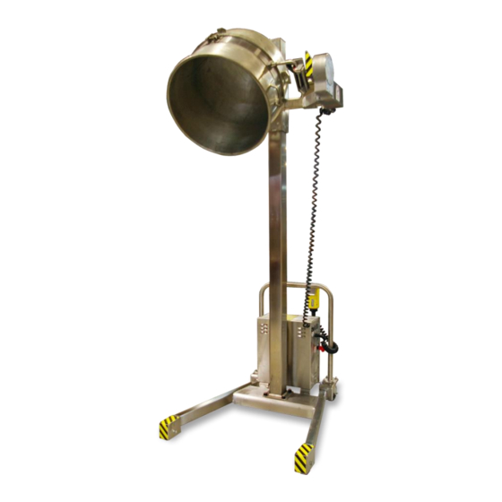
LifTILTruk
Models B, C & D
Installation, Operation, Maintenance
and Parts Manual
Savage Bros. Co.
1825 Greenleaf Avenue
Elk Grove Village, Illinois 60007 – USA
Phone: 847.981.3000
World Fax: 847.981.3010
USA Fax: 800.272.8243 (800-2-SAVAGE)
Internet:
www.savagebros.com
E-mail: info@savagebros.com
fo@savagebros.com
Advertisement
Chapters
Table of Contents
Troubleshooting

Summary of Contents for Savage Bros LifTILTruk B
- Page 1 December 2015 SAVAGE BROS. CO LifTILTruk Models B, C & D Installation, Operation, Maintenance and Parts Manual Savage Bros. Co. 1825 Greenleaf Avenue Elk Grove Village, Illinois 60007 – USA Phone: 847.981.3000 World Fax: 847.981.3010 USA Fax: 800.272.8243 (800-2-SAVAGE) Internet: www.savagebros.com...
-
Page 2: Table Of Contents
Savage Bros. Co. ~ since 1855 LifTILTruk Installation, Operation, Maintenance and Parts Manal CONTENTS CONTENTS LifTILTruk CONTENTS ................................ 2 GENERAL CONCEPT OF OPERATION ......................... 5 WARNINGS ............................... 6 About Batteries ............................8 Specific Cautions when Servicing the LifTILTruk..................9 IMPORTANT SAFETY MEASURES ........................10 General .............................. - Page 3 Savage Bros. Co. ~ since 1855 LifTILTruk Installation, Operation, Maintenance and Parts Manal LifTILTruk Safety and Operation Decals ...................... 26 OPERATION ..............................28 Resetting the Circuit Breaker ........................28 Raising the LifTILTruk Arms ........................28 Lowering the Arms ............................. 28 Adjusting the Span of the Lift Arms ......................
- Page 4 Savage Bros. Co. ~ since 1855 LifTILTruk Installation, Operation, Maintenance and Parts Manal How to check the Down Solenoid Valve ......................62 Up Solenoid Relay ............................63 How to check the Hydraulic Pump Motor ....................63 Replacing the Slide Assembly Bearings ......................64 TROUBLESHOOTING ............................
-
Page 5: Liftiltruk
GENERAL CONCEPT OF OPERATION GENERAL CONCEPT OF OPERATION The Savage Bros. Co. LifTILTruk is designed for the safe lifting, transporting and pouring of a mixing bowl or kettle. The unit is engineered to be operated by one person. A mixing bowl or kettle can be lifted off of a mixer or stove, transported to another location, raised and tilted so that product can be safely poured onto a table or into a hopper or other container. -
Page 6: Warnings
The LifTILTruk is designed and manufactured to be a dependable, predictable and safe tool when used by a SAFE OPERATOR. Savage Bros. Co. cannot predict every circumstance that might involve a potential hazard in operation and maintenance. Therefore, the safety measures in this manual and on the LifTILTruk may not include all possible safety cautions. - Page 7 Savage Bros. Co. kettles or containers of other manufacture which USE A SAVAGE BROS. CO. ADAPTER STRAP. Only Savage kettles or Savage adapter straps are designed to provide support for the loads for which the LifTILTruk was designed.
-
Page 8: About Batteries
Savage Bros. Co. ~ since 1855 LifTILTruk Installation, Operation, Maintenance and Parts Manal About Batteries Each time the battery is discharged then recharged, it goes through a “cycle.” The chemistry in your LifTILTruk battery works when it enjoys very “deep cycles.”... -
Page 9: Specific Cautions When Servicing The Liftiltruk
Savage Bros. Co. ~ since 1855 LifTILTruk Installation, Operation, Maintenance and Parts Manal Specific Cautions when Servicing the LifTILTruk Unplug the LifTILTruk from the outside power source. When plugged in for charging, SERIOUS INJURY OR • DEATH BY ELECTROCUTION CAN RESULT!! Always wear eye protection –... -
Page 10: Important Safety Measures
Savage Bros. Co. ~ since 1855 LifTILTruk Installation, Operation, Maintenance and Parts Manal IMPORTANT SAFETY MEASURES IMPORTANT SAFETY MEASURES General Rotating and moving machinery of any type presents a risk of injury. The LifTILTruk lifts tilts and rolls which means the operator (one trained person at a time only) must be alert at all times. Ideally, everyone who will have any contact with the LifTILTruk should be trained in its function, operation, care and respect –... -
Page 11: Operation Manual And Safety Decals
Replace this manual or safety labels which have been lost or become dirty and cannot be read. Obtain • replacements from Savage Bros. Co. and apply the safety labels in the specified positions. Operating Qualifications Operation of the LifTILTruk should only be done by qualified personnel. Be sure you have proper •... -
Page 12: Unauthorized Modification
Savage Bros. Co. • can create unknown hazards and voids the warranty. Before making any modification, consult the manufacturer. Savage Bros. Co. will not be responsible for • any injury or damage caused by any unauthorized modification. - Page 13 Savage Bros. Co. ~ since 1855 LifTILTruk Installation, Operation, Maintenance and Parts Manal Steering – Control the direction of movement by only using the operator handle. The wheels below • the handle swivel for steering. Moving by pushing or pulling from any other direction can be difficult and dangerous.
-
Page 14: Initial Installation
Step 1. Be certain you have everything you need for the job. Check the shipped contents carefully. • Savage Bros. Co. typically ships two pallets with two cartons for B-size and larger LifTILTruks (Figure 2A). Carton 1 Carton 2 (optional) contains the tilt and idler arms. -
Page 15: Step 2: Prepare The Base Unit For Assembly
Savage Bros. Co. ~ since 1855 LifTILTruk Installation, Operation, Maintenance and Parts Manal Step 2: Prepare the Base unit for Assembly. 1. Disassemble the crate until the base unit looks like DO NOT REMOVE the illustration below (Figure 3). THE ROPE TIE- DOWNS ON THE 2. -
Page 16: Step 3: Remove The Liftiltruk Base From The Pallet
Savage Bros. Co. ~ since 1855 LifTILTruk Installation, Operation, Maintenance and Parts Manal Step 3: Remove the LifTILTruk base from the Pallet. 1. Cut the tie-down ropes holding the LifTILTruk to the Figure 4 pallet (Figure 4). 2. Remove the pallet cross-ties (Figure 5) and use a pry-bar as required to remove them. -
Page 17: Step 4: Prepare The Column For Assembly
Savage Bros. Co. ~ since 1855 LifTILTruk Installation, Operation, Maintenance and Parts Manal Step 4: Prepare the Column for Assembly. 1. Disassemble the crate until the column unit looks Figure 7, like the illustration below (Figure 7). 2. Pry off the two 2x4 blocks (Figure 8) which keep the slide assembly from moving during shipment. - Page 18 Savage Bros. Co. ~ since 1855 LifTILTruk Installation, Operation, Maintenance and Parts Manal 7. Locate the hydraulic fuse “stored” in the end of the Figure 12 hydraulic line inside the control box (Figure 12). Locate hydraulic “fuse”. 8. Remove hydraulic fuse from the end of the hydraulic hose.
-
Page 19: Step 5: Lift The Column Over The Base
Savage Bros. Co. ~ since 1855 LifTILTruk Installation, Operation, Maintenance and Parts Manal Step 5: Lift the Column over the Base. 1. Install a sling system to allow lifting and positioning the Figure 15 column safely. For the sling, use web strapping in good Create a strap hoist. -
Page 20: Step 6: Bolt The Column To The Base
Savage Bros. Co. ~ since 1855 LifTILTruk Installation, Operation, Maintenance and Parts Manal First move the back part of the LifTILTruk next to a wall if possible to stabilize it. Doing this task without a positive lifting and stabilizing method is not at all recommended. - Page 21 Savage Bros. Co. ~ since 1855 LifTILTruk Installation, Operation, Maintenance and Parts Manal 4. Pull down and route the open end of the hydraulic hose Figure 19 through the hole in the base of the electrical control box (Figure 19) and attach it to the hydraulic fuse attached in step 11 of “Prepare the Column for Assembly”...
-
Page 22: Step 8: Major Electrical Connections
Savage Bros. Co. ~ since 1855 LifTILTruk Installation, Operation, Maintenance and Parts Manal Step 8: Major Electrical Connections. Connect the RED cable to the positive battery terminal. Figure 20 The terminal wing-nut should be tightened “finger tight” and should not be easily loosened. -
Page 23: Step 9: Perform The Initial Hydraulic System Check
Savage Bros. Co. ~ since 1855 LifTILTruk Installation, Operation, Maintenance and Parts Manal Step 9: Perform the Initial Hydraulic System Check. 1. Remove the C-clamp from the column. Figure 24 2. Using the operator control, (Figure 24) press the UP button until the slide assembly is about half-way up the column. -
Page 24: Step 10: Install The Lifting Arms
Savage Bros. Co. ~ since 1855 LifTILTruk Installation, Operation, Maintenance and Parts Manal Step 10: Install the Lifting Arms. 1. Remove the screw, washer and retainer plate from the Figure 25 end of the right slide assembly arm (Figure 25). -
Page 25: Step 12: Test The Completed Liftiltruk
Ask for assistance If you need adapter straps for special container sizes, types and loads, please call Savage Bros. Co. for assistance. Our phone/fax numbers and web addresses are on the front cover of this manual. -
Page 26: Liftiltruk Safety And Operation Decals
• VISUALLY INSPECT and clean CHAIN periodically. Lubrication: food-grade lithium grease. To order a new set of decals from Savage Bros. Co., • Realice una INSPECCIÓN VISUAL y limpie la CADENA periódicamente. Lubricante: grasa con litio de uso en la producción de alimentos. - Page 27 Savage Bros. Co. ~ since 1855 LifTILTruk Installation, Operation, Maintenance and Parts Manal TOP OF CONTROL BOX 1. Cut entire label, with its backing, away from sheet. 2. Peel backing at (A) about 1 to 2 inches and, with adhesive up, crease backing paper.
-
Page 28: Operation
Savage Bros. Co. ~ since 1855 LifTILTruk Installation, Operation, Maintenance and Parts Manal OPERATION OPERATION Resetting the Circuit Breaker N O TE: If the tilt button is not released when the tilt mechanism is at either end of its travel, the circuit breaker will trip to prevent damage to the tilt motor. -
Page 29: Adjusting The Span Of The Lift Arms
Savage Bros. Co. ~ since 1855 LifTILTruk Installation, Operation, Maintenance and Parts Manal Adjusting the Span of the Lift Arms WARNING The lift arms are free to move on the slide assembly arms but are prevented from sliding off by a plate at either end of the slide assembly arms. Be sure these plates are in place before adjusting the arms. -
Page 30: Adjusting The Latches
Savage Bros. Co. ~ since 1855 LifTILTruk Installation, Operation, Maintenance and Parts Manal Adjusting the Latches WARNING The lifted container can be any container, of any configuration, AS LONG AS IT IS EITHER A SAVAGE CONTAINER, OR ONE USING A SAVAGE ADAPTER STRAP. -
Page 31: Pouring From A Container
Savage Bros. Co. ~ since 1855 LifTILTruk Installation, Operation, Maintenance and Parts Manal WARNING NEVER TRANSPORT A CONTAINER UNLESS THE LIFTILTRUK COLUMN SLIDE IS IN THE FULL DOWN POSITION. Pouring from a Container 1. Make certain handles are locked in latches (Figure 31). -
Page 32: Removing A Container From The Liftiltruk
Savage Bros. Co. ~ since 1855 LifTILTruk Installation, Operation, Maintenance and Parts Manal Removing a Container from the LifTILTruk 1. Raise the container until it is positioned directly over Figure 33 the receiving equipment, dolly or other support required. Tip both latch lock... -
Page 33: Periodic Maintenance
Savage Bros. Co. ~ since 1855 LifTILTruk Installation, Operation, Maintenance and Parts Manal PERIODIC MAINTENANCE PERIODIC MAINTENANCE Periodic Maintenance Chart 5, 9 Figure Service Action N o. Item Interval Reference Painted and metal surfaces W ipe with damp cloth to keep clean. -
Page 34: Periodic Maintenance
Savage Bros. Co. ~ since 1855 LifTILTruk Installation, Operation, Maintenance and Parts Manal Periodic Maintenance Figure 34 Figure 35 Figure 36 Painted and metal surfaces – wipe Latch Mechanisms – Check for free Operator’s Control and switch covers with a damp cloth and keep clean –... -
Page 35: Column
Savage Bros. Co. ~ since 1855 LifTILTruk Installation, Operation, Maintenance and Parts Manal Figure 40 Figure 42 Figure 41 Column – Lubricate (spray onto Wheels – Lubricate with grease gun Idler Mechanism Assembly – Lubricate column) with food grade, white –Monthly. -
Page 36: Tilt Gearbox
Savage Bros. Co. ~ since 1855 LifTILTruk Installation, Operation, Maintenance and Parts Manal Worm Gear Tilt Gearbox Lubrication 1. Remove the eleven 8/32 inch flat head cap screws Figure 47a holding the gearbox main cover and lower cover. 2. Check to be sure that worm gear makes contact with oiled sponge. -
Page 37: Servicing The Liftiltruk
Savage Bros. Co. ~ since 1855 LifTILTruk Installation, Operation, Maintenance and Parts Manal SERVICING THE LIFTILTRUK SERVICING THE LIFTILTRUK IN ORDER TO PERFORM SERVICE AND MAINTENANCE, ONLY CERTIFIED ELECTRICAL TECHNICIANS SHOULD OPEN THE ELECTRICAL CONTROL BOX. Main Control Box In the event that service such as replacing the fuse or the battery is required inside the main control box, first disconnect the machine’s electrical power cord from the charging socket (Figure 48). -
Page 38: Battery Charging - Inside The Control Box
Savage Bros. Co. ~ since 1855 LifTILTruk Installation, Operation, Maintenance and Parts Manal Battery Charging - Inside the Control Box 1. Plug in a common heavy-duty 3-wire extension cord from a Figure 49 110-volt 60Hz service outlet (or to other voltage source if listed on decal on side of control box) to the charging socket on the LifTILTruk control box. -
Page 39: Servicing The Battery
Savage Bros. Co. ~ since 1855 LifTILTruk Installation, Operation, Maintenance and Parts Manal Servicing the Battery IN ORDER TO PERFORM SERVICE AND MAINTENANCE, ONLY CERTIFIED ELECTRICAL TECHNICIANS SHOULD OPEN THE ELECTRICAL CONTROL BOX. Testing the Battery As long as the LifTILTruk seems to be “working OK” – it does the work you expect it to do and in a reasonable amount of time between charging, there is no reason to test the battery. - Page 40 Savage Bros. Co. ~ since 1855 LifTILTruk Installation, Operation, Maintenance and Parts Manal Replacing the Battery 1. Be sure the charging cable is NOT plugged into the charging socket on the electrical control box. 2. Push the circuit breaker switch so it is in the down position to turn off current flow in the LifTILTruk circuits.
-
Page 41: Servicing The Battery Charger
Savage Bros. Co. ~ since 1855 LifTILTruk Installation, Operation, Maintenance and Parts Manal Servicing the Battery Charger IN ORDER TO PERFORM SERVICE AND MAINTENANCE, ONLY CERTIFIED ELECTRICAL TECHNICIANS SHOULD OPEN THE ELECTRICAL CONTROL BOX. Testing the Battery Charger 1. Install a fully charged battery into the LifTILTruk. (See Replacing the Battery, page 40). It must be a new or nearly new battery which has been charged overnight using an external charger, not the one on the LifTILTruk. - Page 42 Savage Bros. Co. ~ since 1855 LifTILTruk Installation, Operation, Maintenance and Parts Manal Replacing the Battery Charger Required tools • 5/16” Allen wrench. • Medium flat blade screwdriver. 7/16" socket with 3" extension or combination wrench. • • 1/2" and 9/16" wrench.
- Page 43 Savage Bros. Co. ~ since 1855 LifTILTruk Installation, Operation, Maintenance and Parts Manal Corner Mounting Screw Remove the Battery Charger Assembly 1. Remove the 2 corner mounting screws holding the terminal strip to the front of the charger bracket. Let the strip hang by its wires (Figure 56).
-
Page 44: Servicing The Voltmeter
Savage Bros. Co. ~ since 1855 LifTILTruk Installation, Operation, Maintenance and Parts Manal Install the Replacement Charger 1. Mount the replacement charger. Attach the green ground wires. Secure the 4 nuts that fasten it to the top of the control box. - Page 45 Savage Bros. Co. ~ since 1855 LifTILTruk Installation, Operation, Maintenance and Parts Manal 4b ...back terminal of emergency stop switch. If yes, proceed to 4c. If no, disconnected (+) battery cable. 4c ...front terminal of emergency stop switch (Figure 58). If yes, proceed to 4d.
- Page 46 Savage Bros. Co. ~ since 1855 LifTILTruk Installation, Operation, Maintenance and Parts Manal 4. Put the positive test probe onto the positive battery terminal. Test with negative probe for voltage greater than 10 volts on: 5a ...the bare metal mounting strap of the solenoid (Figure 63). If yes, proceed to 5b.
-
Page 47: Servicing The Circuit Breaker
Savage Bros. Co. ~ since 1855 LifTILTruk Installation, Operation, Maintenance and Parts Manal Servicing the Circuit Breaker Testing the Circuit Breaker 1. Put on safety goggles or face shield meeting ANSI Z87.1 specifications. 2. Open the electrical control box door using the 5/16 inch allen wrench. - Page 48 Savage Bros. Co. ~ since 1855 LifTILTruk Installation, Operation, Maintenance and Parts Manal Remove the nut and lockwasher from the negative terminal of the battery (see Figures 66 and 67). Tuck the cable out of the way so it cannot touch the negative battery terminal (Figure 68).
- Page 49 Savage Bros. Co. ~ since 1855 LifTILTruk Installation, Operation, Maintenance and Parts Manal Remove screw from Remove nut from Replacing the Circuit Breaker Circuit Breaker. Circuit Breaker. 1. On the outside of the electrical control box, remove the screw and nut holding the circuit breaker unit in place (Figures 69 and 70).
-
Page 50: Servicing The Ammeter
Savage Bros. Co. ~ since 1855 LifTILTruk Installation, Operation, Maintenance and Parts Manal Servicing the Ammeter Testing the Ammeter 1. If the ammeter is suspected to be faulty, install a discharged battery in the LifTILTruk using the instructions in “Replacing the Battery”... -
Page 51: Servicing The Inline Fuse
Savage Bros. Co. ~ since 1855 LifTILTruk Installation, Operation, Maintenance and Parts Manal Servicing the Inline Fuse Remove the Fuse. If your LifTILTruk has an inline fuse, it should be checked whenever the battery charger does not move the voltmeter... -
Page 52: Lifttiltruk Tilt Motor Troubleshooting
Savage Bros. Co. ~ since 1855 LifTILTruk Installation, Operation, Maintenance and Parts Manal 3. Tilt the LifTILTruk backwards and slide another block, Figure 76 identical to the rear block, under the front of the frame legs (Figure 76). Servicing to the wheels, casters, column or associated hydraulic parts can now be performed. - Page 53 Savage Bros. Co. ~ since 1855 LifTILTruk Installation, Operation, Maintenance and Parts Manal 6. Place the red multimeter lead on terminal #3 on the terminal strip. Place the black multimeter lead on terminal Terminal #1 #1 on the terminal strip (Figure 78). The voltage reading on (Black Lead) the multimeter needs to be 0V.
-
Page 54: Replacing Pendant Switches And Switch Components
(Black Lead) If all the voltages are correct going to the tilt motor coil cord connector, the tilt motor assembly may need to be replaced, contact Savage Bros. Co. for assistance. Please REVERSE” Figure 81 – " make the model number and serial number readily Position available when contacting savage Bros. -
Page 55: Checking Or Adding Hydraulic Fluid
Savage Bros. Co. ~ since 1855 LifTILTruk Installation, Operation, Maintenance and Parts Manal Hydraulic Reservoir Checking or Adding Hydraulic Fluid Filler Cap 1. Lower the slide assembly to the bottom of the column. Figure 82 2. Put on safety goggles or face shield meeting ANSI Z87.1 specifications. - Page 56 Savage Bros. Co. ~ since 1855 LifTILTruk Installation, Operation, Maintenance and Parts Manal 14. Using an appropriate sling and lifting system, pull the column upward, free of the base, while carefully leading the hydraulic return tubing out of the hole in the base, see “Lift the Column Over the Base”...
-
Page 57: Replacing The Hydraulic Cylinder Seal
Savage Bros. Co. ~ since 1855 LifTILTruk Installation, Operation, Maintenance and Parts Manal Replacing the Hydraulic Cylinder Seal Refer to Figure 83. 1. Before the hydraulic cylinder can be serviced the Figure 83 column must be removed from the base. Use the instructions in “Removing and Replacing the... - Page 58 Savage Bros. Co. ~ since 1855 LifTILTruk Installation, Operation, Maintenance and Parts Manal Remove the old O-ring from the rod and replace it with the new O-ring in the repair kit. Remove the old piston seal from the piston sleeve and insert the piston sleeve in the new seal provided in the repair kit.
-
Page 59: Replacing The Chain And Idler Wheel
N O TE: If you do not own a professional quality chain breaker tool, or if you do not have experience working with this tool, Savage Bros .Co. urgently recommends that you employ the services of a professional repair person who is experienced in this operation. A poor chain replacement job can result in failure of the chain retaining mechanism with serious injury or DEATH resulting from loss of the lifting chain. -
Page 60: Replacement Of The Tilt Motor Coil Cord And Connector
Savage Bros. Co. ~ since 1855 LifTILTruk Installation, Operation, Maintenance and Parts Manal Replacement of the Tilt Motor Coil Cord and Connector 1. Put on safety goggles or face shield meeting ANSI Z87.1 Figure 84 specifications. 2. Open the electrical control box door using the 5/16 inch allen wrench. -
Page 61: Replacing The Tilt Motor Drive
Replacing the Tilt Motor Drive NOTE: The Tilt Motor is under warranty terms. If it is replaced directly by the customer, the warranty will not be honored unless approved in advance by Savage Bros. Co. Remove screws 1. Remove the three screws holding cover over tilt gear motor (Figure 87). -
Page 62: Lubricating The Column
Savage Bros. Co. ~ since 1855 LifTILTruk Installation, Operation, Maintenance and Parts Manal 4. Remove the four cap screws (Figure 90) holding the motor mounting plate to the tilt gearbox and pull the motor and mount away from the gearbox. -
Page 63: Up Solenoid Relay
Savage Bros. Co. ~ since 1855 LifTILTruk Installation, Operation, Maintenance and Parts Manal When the column slide assembly is lowered or secured in a stationary position, follow the procedures for removing the battery on page 40. Put a pan under the control control box and hydraulic hose to catch any hydraulic fluid that will come out when the hydraulic hose fitting is loosened. -
Page 64: Replacing The Slide Assembly Bearings
Savage Bros. Co. ~ since 1855 LifTILTruk Installation, Operation, Maintenance and Parts Manal Replacing the Slide Assembly Bearings After continuous usage, the slide assembly bearings may need to be replaced. In order to replace the slide assembly bearings, follow the steps below. -
Page 65: Troubleshooting
Savage Bros. Co. ~ since 1855 LifTILTruk Installation, Operation, Maintenance and Parts Manal TROUBLESHOOTING TROUBLESHOOTING PROBLEM CAUSE SOLUTION PAGE Bowl adapter strap not installed. Install bowl adapter strap. Native bowl Bowl handles do not fit handles are not designed for lifting and into supports on LifTILTruk tilting. - Page 66 Savage Bros. Co. ~ since 1855 LifTILTruk Installation, Operation, Maintenance and Parts Manal TROUBLESHOOTING (CONTINUED) PROBLEM CAUSE SOLUTION PAGE Bowl will not rise Battery charge is low; not enough Check the battery state of when UP button is charge to start the motor.
- Page 67 Savage Bros. Co. ~ since 1855 LifTILTruk Installation, Operation, Maintenance and Parts Manal TROUBLESHOOTING (CONTINUED) PROBLEM CAUSE SOLUTION PAGE Bowl will not rise all the way Not enough hydraulic fluid in the pump Add hydraulic fluid. to the top of the column: reservoir.
- Page 68 Savage Bros. Co. ~ since 1855 LifTILTruk Installation, Operation, Maintenance and Parts Manal TROUBLESHOOTING (CONTINUED) PROBLEM CAUSE SOLUTION PAGE Bowl tilts with a jerky Lifting arms are too close or too far apart Adjust the span of the lifting arms to match movement, or the bowl easily engage handles.
-
Page 69: Warranty Policy
4. If the defective part does not need to be returned, the invoice for the replacement part will include the full credit. 5. In most instances, parts are designed to be installed by the user. At the option of Savage Bros. Co., it may authorize the customer to obtain local installation service assistance. If necessary, labor for part installation is determined to be warranty, Savage Bros. -
Page 70: Mechanical Drawings And Mechanical Parts
Savage Bros. Co. ~ since 1855 LifTILTruk Installation, Operation, Maintenance and Parts Manal MECHANICAL DRAWINGS AND MECHANICAL PARTS MECHANICAL DRAWINGS AND MECHANICAL PARTS Electrical/Hydraulic Control Box, see page Control Pendant Assembly, see page Basic Mechanical Units, see page Left Arm Assembly, see... -
Page 71: Electrical/Hydraulic Control Box
Savage Bros. Co. ~ since 1855 LifTILTruk Installation, Operation, Maintenance and Parts Manal Electrical/Hydraulic Control Box ITEM PART NO. DESCRIPTION Battery Specifications: 160-180 reserve minutes 0708-08-008 Ele/Hydr. Box-LTT Battery - CRS or 80-100 amp-hours 9400-33-092 Schauer Charging Mounting Bracket 9400-20-352 Battery Charger (For Batt. -
Page 72: Control Pendant Assembly
Savage Bros. Co. ~ since 1855 LifTILTruk Installation, Operation, Maintenance and Parts Manal Control Pendant Assembly ITEM PART NO. DESCRIPTION 0712-08-410 Autotilt Pendant Control Assembly 9400-30-163 Pendant Enclosure 3 Hole, For LTT 0712-08-004 Yellow Pendant Coil Cord 9400-30-166 Button W/Boot White, For LTT Up... -
Page 73: Basic Mechanical Units
Savage Bros. Co. ~ since 1855 LifTILTruk Installation, Operation, Maintenance and Parts Manal Basic Mechanical Units ITEM PART NO. DESCRIPTION 0711-01 Base Assembly. Model C 0712-02-610 Column Subassembly 0712-08 Electric - Hydraulic 12VDC Box 0708-02-001 Column Cap Slide Column –... -
Page 74: Left Arm Assembly
Savage Bros. Co. ~ since 1855 LifTILTruk Installation, Operation, Maintenance and Parts Manal Left Arm Assembly ITEM PART NO. DESCRIPTION 0712-03-600 Arm Left -Tilt Assembly, Standard 0711-03-606 Arm, Liftil Truck B-C, Left 0712-04-630 Gearbox 9400-00-665 Tilt Motor Asm Std Torque... -
Page 75: Idler Mechanism Assembly
Savage Bros. Co. ~ since 1855 LifTILTruk Installation, Operation, Maintenance and Parts Manal Idler Mechanism Assembly ITEM PART NO. DESCRIPTION Idler Drive Cast – Shaft 711-03-660 Mechanism 0708-03-024 LifTILTruk Idler Double Locked Machined 9200-60-103 Clevis Pin - .25 O.D - 1LG 9200-60-104 Rue Ring for 1.4 Clevis Pin... -
Page 76: Standard Gearbox Assembly
Savage Bros. Co. ~ since 1855 LifTILTruk Installation, Operation, Maintenance and Parts Manal Standard Gearbox Assembly ITEM PART NO. DESCRIPTION 0712-04-630 Gearbox 0712-90-050 Gearbox Housing 0712-04-052 LTT Gearbox Main Cover 0712-04-054 LTT Gearbox Lower Cover 9700-00-002 Worm Gear Helical 9700-00-001 Worm Gear ¾”... -
Page 77: Right Arm Assembly
Savage Bros. Co. ~ since 1855 LifTILTruk Installation, Operation, Maintenance and Parts Manal Right Arm Assembly ITEM PART NO. DESCRIPTION 0711-03-610 Right Arm (Idler) Assembly 0711-03-605 Lift Arm Frame, Model B-C 0712-90-006 Bearing Housing Assembly 0711-03-830 Idler Mechanism Assembly Bowl Strap PART NO. -
Page 78: Hydraulic Cylinder Assembly
Savage Bros. Co. ~ since 1855 LifTILTruk Installation, Operation, Maintenance and Parts Manal Hydraulic Cylinder Assembly ITEM PART NO. DESCRIPTION 0712-02-620 Hydraulic Cylinder Assembly 0708-02-101 Idler Wheel- Axle and Bearing 1/4-20 X 1/4" Cup Point Set Screw, Blk 9200-10-116 Rod Wiper... -
Page 79: Hydraulic Cylinder Seal Replacement Kit
Savage Bros. Co. ~ since 1855 LifTILTruk Installation, Operation, Maintenance and Parts Manal Hydraulic Cylinder Seal Replacement Kit ITEM PART NO. DESCRIPTION Hydraulic Cylinder Seal 0711-02-701 Replacement Kit O Ring 3/8" x 1/2" x 1/16" - 012 9700-60-914 VITON Piston Sleeve... -
Page 80: Electrical Schematics And Electrical Parts
Savage Bros. Co. ~ since 1855 LifTILTruk Installation, Operation, Maintenance and Parts Manal ELECTRICAL SCHEMATICS AND ELECTRICAL PARTS ELECTRICAL SCHEMATICS AND ELECTRICAL PARTS page LifTILTruk Electrical Control Circuit Diagram, page LifTILTruk Electrical Replacement Parts, LifTILTruk December 2015... -
Page 81: Liftiltruk Electrical Control Circuit Diagram
Savage Bros. Co. ~ since 1855 LifTILTruk Installation, Operation, Maintenance and Parts Manal LifTILTruk Electrical Control Circuit Diagram LifTILTruk December 2015... -
Page 82: Liftiltruk Electrical Replacement Parts
Savage Bros. Co. ~ since 1855 LifTILTruk Installation, Operation, Maintenance and Parts Manal LifTILTruk Electrical Replacement Parts LifTILTruk December 2015...
Need help?
Do you have a question about the LifTILTruk B and is the answer not in the manual?
Questions and answers