
Summary of Contents for TBB SP Series
- Page 1 SP60/SP80 User Manual V1.3 SP solar charge controller MPPT SP60-150 MPPT SP80-150 USER MANUAL Version 1.3 Date: August. 2015 TBB Power Co.,Ltd...
- Page 2 SP60/SP80 User Manual V1.3 TBB Power Co.,Ltd...
- Page 3 Assumes no responsibility or liability for loss or damage, whether direct, indirect, consequential or incidental, which might arise out of the use of such information TBB offer standard warranty with its products, taking no responsibility for direct or indirect loss due to equipment failure.
- Page 4 SP60/SP80 User Manual V1.3 TBB Power Co.,Ltd...
-
Page 5: General Instruction
5> While connecting wires, please secure the connection and avoid short cut between positive terminal and negative terminal of battery, which will cause damage of battery. 6> MPPT charge controller will have high voltage inside. Only authorized electrician can open the case. TBB Power Co.,Ltd... -
Page 6: Table Of Contents
2.0 Description of main Function ..........................7 2.1 General Description ............................7 2.2 Maximum Power Point Tracking ......................8 2.3 Battery charging control ..........................9 2.4 TBB premium II charging algorithm......................9 2.5 Auxiliary output ............................ 11 2.6 Comprehensive Protection ........................12 3.0 Structure ................................. 13 3.1 Front .............................. - Page 7 5.5.1 Alarm ............................36 5.5.2 History ............................37 6.0 Operation ............................... 39 6.1 Viewing system status ..........................39 6.2 Viewing Log Data ..........................40 6.3 Equalization Charging (EQ charging) ..................... 41 7.0 Specification ..............................43 8.0 Trouble Shooting ............................44 TBB Power Co.,Ltd...
-
Page 8: General Safety Instruction
1.3.3. Do not put the metal tool on the battery, spark and short circuit might lead to explosion. 1.3.4. REMOVE all personal metal items such as rings, bracelets, necklaces, and watches while working with batteries. Batteries can cause short-circuit current high enough to make metal melt, and could cause severe burns. TBB Power Co.,Ltd... -
Page 9: Description Of Main Function
Thanks to its self cooling design, it is suitable for most rugged environment with dust or bugs. SP60/80-150 can operate at their full rating in ambient temperatures as high as 40℃. TBB Power Co.,Ltd... -
Page 10: Maximum Power Point Tracking
Built in dynamic Maximum Power Point Tracking Continuous operation at full power up to 40℃ Self cooling design for high reliability Built in TBB premium II battery charging algorithm for lead acid battery Configurable auxiliary contact Data logging ... -
Page 11: Battery Charging Control
SP60/SP80 User Manual V1.3 2.3 Battery charging control With built in TBB premium II charging algorithm, SP automatically regulated the voltage and current according to the DC source available from PV array and SOC of battery connected. The SP60/80-150 is able to charge a lower nominal voltage battery from a higher nominal voltage array. - Page 12 For details, please refer to chapter 6.3 This charging program can ONLY being applied to semi traction , traction and flooded lead-acid battery. As a protection, the EQ mode will automatically disable if you select either GEL or AGM as battery type. TBB Power Co.,Ltd...
-
Page 13: Auxiliary Output
The auxiliary contact can be configured to switch the alarm circuit or indicator light on upon preset condition occurs, such as MPPT failure, battery low voltage, high PV input voltage etc. TBB Power Co.,Ltd... -
Page 14: Comprehensive Protection
During charging, the SP will keep monitoring battery temperature and will reduce charging rate or even shut down upon too high temperature detected. This will help to prevent thermal runaway of battery. TBB Power Co.,Ltd... -
Page 15: Structure
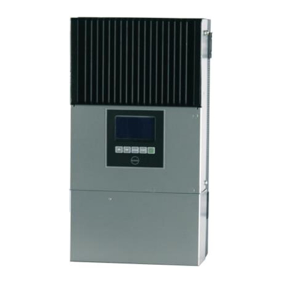
SP60/SP80 User Manual V1.3 3.0 Structure 3.1 Front Fig3-1 Charge controller structure in front view Heat sink Control button Connection compartment TBB Power Co.,Ltd... -
Page 16: Lcd And Control Panel
Decrease the value of the selected item Enter into this menu, displaying the next level Select and confirm the selection of a menu item Cancel the selection Display the previous level of menu Power On/Off TBB Power Co.,Ltd... -
Page 17: Connection Compartment
Tab3-4and Tab3-5 is PIN definition of PCB Connector E and Connector G. Definition Pin1 Auxiliary contact (Common terminal) Pin2 Auxiliary contact(Normally Open) Pin3 Auxiliary contact(Normally Closed) Pin4 HV input, Positive Pin5 HV input, Negative Definition Pin1,2 VCC_485(12VDC) Pin3,4 RS485 - B/CAN-L Pin5,6 RS485 - A/CAN-H Pin7,8 GND_485 TBB Power Co.,Ltd... -
Page 18: Dimension
SP60/SP80 User Manual V1.3 3.4 Dimension Fig3-4 Dimension of SP60/80 charge controller TBB Power Co.,Ltd... -
Page 19: Installation
Maximize the harvest of solar energy Charging SP shut down. Voc is often higher than Overvoltage Vmpp > 135Vdc 150VDC when Vmpp is higher than 135V fault DC. Unit might damage if Voc>150V Tab4-1 Effects of different PV array voltage TBB Power Co.,Ltd... -
Page 20: Location
Do not install SP in a sealed compartment containing batteries. Please always guarantee the enough clearance around SP upon installation. Please refer to following fig 4-1 for minimum clearance. AT LEAST 150mm(6inch) AT LEAST AT LEAST 50mm(2inch) 150mm(6inch) Fig 4-1 Requirement of minimum clearance TBB Power Co.,Ltd... -
Page 21: Cable Recommendation
The SP must be compliant with all local electrical guidelines. Installation of this equipment should be performed by a qualified electrician. Upon installation, please make sure SP was switched off and all circuit breaker was at OFF and fuse was open. TBB Power Co.,Ltd... -
Page 22: Preparation
Screw the four screw on the wall, leaving about 6mm (1/4”). Hanging the SP on the four screws and screw tight the four screws afterwards. Please double check the SP was securely mounted on the wall. TBB Power Co.,Ltd... -
Page 23: Wiring Diagram
SP60/SP80 User Manual V1.3 4.4.3 Wiring Diagram Please refer to following overall wiring diagram of SP60/80-150 TBB Power Co.,Ltd... -
Page 24: Battery Connection
Secure the battery cable on BAT+ and BAT- terminals respectively making sure it is tightly screwed Please double confirm the polarity of battery input. SP will not be able to switch on with reverse polarity connection. TBB Power Co.,Ltd... -
Page 25: Installing The Battery Temperature Sensor (Bts)
Adding diode between PV array and MPPT preventing reverse current at night to PV. An over current protection devices DC fuse or circuit breaker needs to be installed on positive cable, of which rated for 100% of the nominal rating. SP60-150: TBB Power Co.,Ltd... -
Page 26: Grounding Connection
Do not connect the PV negative and battery negative terminal together at any place of the system. They must be connected to corresponding terminal marked at connection compartment. Wrong connection might cause equipment damage which is out of warranty. TBB Power Co.,Ltd... -
Page 27: Connecting The Multiple Units
In a multiple unit installation, each SP charge controller need to be connected to a separate PV array. Please make sure each SP charge controller was connected with its own PV array. The mixing connection will cause damage which is out of warranty. TBB Power Co.,Ltd... -
Page 28: Auxiliary Output Connection
Recommend wait for a few minutes before opening the case. Switched off the SP charge controller Disconnecting the PV array. Disconnecting the battery You can remove the SP charge controller for necessary maintenance TBB Power Co.,Ltd... -
Page 29: Lcd Menu And Configuration
Month-12 2014/04/05 09:15:15 Monthly logs Notice #1999 Peak W 3280W Peak W 3280W 05020202 05020211 Clock set done 122.3KWH 122.4KWH 050103 050203 2013/11/02 19:13:22 Total Alarm #23 280.0KWH Over temperature 050204 Life 888.0KWH Fig 5-1Complete Menu Map TBB Power Co.,Ltd... -
Page 30: Status Page
Fig 5-2 Status page 5.2 Information Page This page contain basic information of this equipment. Press entering into next page. 0201 Information Type/mode: SP80A 48V 0202 Control firmware version: 00.01.0002 0203 LCD firmware version: 00.02.0004 Fig5-3 Information page TBB Power Co.,Ltd... -
Page 31: Setting Page And Configuration
Temperature compensation rate Charger Equalization voltage Charger Equalization timer It is important to finish the basic configurations listed below to assure the right performance and display of this equipment. Some setting such as battery type is compulsory to finish. TBB Power Co.,Ltd... -
Page 32: Entering Into Setting
When you enter into the Setting Page, the password was requested. Only with this password, you can enter into the advanced setting. (page 0312-0318) Without entering password or entering into wrong password, you can enter into basic setting only. (page 0301-0311) The default password is 1234 TBB Power Co.,Ltd... -
Page 33: Basic Configuration
Date and Time GMT+8 Please set your time zone Tab5-1 Content of Basic System Setting It was highly recommended changing password and keep in privacy. Only professional can enter into advanced setting. TBB Power Co.,Ltd... - Page 34 26.4 52.8 15.5 Flooded Tab5-3 Default Battery Type Please double check if the above charging voltage matching your battery manufacturer’s recommendation. If not, you can adjust the voltage in advanced configuration page after you make the choice. TBB Power Co.,Ltd...
- Page 35 Will send signal once EQ charging stage was triggered The figure can’t be reset. This can PV input high be used to trigger on an alarm or 135Vdc 135Vdc voltage disconnecting the PV array from the MPPT. Tab5-5 Auxiliary output setting TBB Power Co.,Ltd...
-
Page 36: Advanced Configuration
Charger Equalization voltage 15.0-16.5Vdc default Changing the max time of Charger Equalization timer 30mins-2hrs 30mins Equalization charging stage Tab5-6 Advanced Battery Configuration Notice For above default setting, please refer to chapter 5.3.2 Default battery types and charging voltage. TBB Power Co.,Ltd... -
Page 37: Control Page
After enter into this page, through pressing “ENTER” button, you can clear the history records. Only Daily logs, Monthly logs and Life can be cleared. Total record can’t be cleared. After enter into this page, through pressing “ENTER” button, you can reset the default factory setting values. TBB Power Co.,Ltd... -
Page 38: Event Log
After enter into this page, press “ENTER” button, you can read all alarm info by pressing “UP” and “DOWN” button. Equipment will record all alarm info with its date and time Max 200 records can be available from TBB Power Co.,Ltd... -
Page 39: History
Within this page, through pressing “UP” and “DOWN” button, you can approach various history records Daily logs Monthly logs Total: record of total output of this installation Life : record of total output of life performance TBB Power Co.,Ltd... - Page 40 It can’t be reset to zero 050204 Life 888.0KWH Fig5-13 Life Log Page It will show the accumulated KWH of this installation. It can be reset to zero if you want to start the log again. TBB Power Co.,Ltd...
-
Page 41: Operation
If system self-testing is OK, the MPPT will start deliver charging to battery connected and LCD will display system status page. 6.1 Viewing system status You will see first page which shows the system status. Input 120V 60A Alarm #25 Output 80V 60A PV voltage high Fig6-1System status page TBB Power Co.,Ltd... -
Page 42: Viewing Log Data
KWH recorded of this installation. This TOTAL can be reset. Press "Enter" to vew the LIFE logs. Total log contained accumulated KWH Life recorded of this unit since first use. This can not be reset. Tab6-1 Viewing Log Data TBB Power Co.,Ltd... -
Page 43: Equalization Charging (Eq Charging)
During equalization, the battery generates potentially flammable gases. Follow all the battery safety precautions listed in this guide. Ventilate the area around the battery thoroughly and ensure that there are no sources of flame or sparks in the vicinity TBB Power Co.,Ltd... - Page 44 Battery type As a protection, equalization charging can be performed if and ONLY if you set the battery to be semi traction or traction lead-acid/OPZS batteries. If you choose AGM or GEL, EQ charging can’t be performed. TBB Power Co.,Ltd...
-
Page 45: Specification
1800W 2300W 48Vdc 3500W 4600W Max efficiency (full load) 98%@48Vdc system Standby power consumption <2W Charging algorithum TBB II multiple stages Temperature compensation Automatic, -4mV/C/cell Equalization charging By manual Others RS485 Communication port Auxiliary contact 1 programmable 365days of history record - peak watts for every... -
Page 46: Trouble Shooting
Short-circuit fault occurs in PV input Check PV array. circuit, input voltage is zero voltage. LCD shows SP charge Overheat protection of the SP unit SP charger can resume charging over temperature automatically after the temperature fall into range. Fig8-1 Trouble Shooting TBB Power Co.,Ltd... - Page 47 SP60/SP80 User Manual V1.3 TBB Power Co.,Ltd...
- Page 48 SP60/SP80 User Manual V1.3 TBB Power Co.,Ltd...
Need help?
Do you have a question about the SP Series and is the answer not in the manual?
Questions and answers