Table of Contents
Advertisement
Quick Links
Advertisement
Table of Contents

Summary of Contents for ILX Lightwave LDM-4980 Series
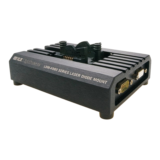
- Page 1 User’s Guide LDM-4980 Series Laser Diode Mount ILX Lightwave Corporation P. O. Box 6310 Bozeman, MT, U.S.A. 59771 · · · U.S. & Canada 1-800-459-9459 · International Inquiries: 406-586-1244 Fax 406-586-9405 · E-mail: support@ilxlightwave.com www.ilxlightwave.com 70022504_R01_05_05...
-
Page 3: Table Of Contents
LDM-4986 Wiring ..........9 LDM-4983 and LDM-4989 Hotplate and Laser Diode Case Potential Wiring ....11 07_04 LDM-4980 Series... - Page 4 Electrical Precautions ......... . 12 ILX Lightwave Current Source Interlock Feature ....12 ILX Lightwave Model CC305S Interconnect Cable .
-
Page 5: List Of Figures
Figure 2.3 Fujitsu “LK” Package Laser Diode ....10 Figure 2.4 LDM-4892M Pin 1 Location ..... . . 14 07_04 LDM-4980 Series... - Page 6 L I S T O F F I G U R E S LDM-4980 Series...
-
Page 7: List Of Tables
ABLES Table 1.1 ILX Lightwave Mount Types and Packages ... . . 2 Table 2.1 Laser Diode Pin Configuration with Internal TEC..7 Table 2.2 Butterfly Package Wiring Configuration . - Page 8 L I S T O F TA B L E S LDM-4980 Series...
-
Page 9: Safety And Warranty Information
• Prolonged storage under adverse conditions • Failure to perform intended measurements or functions If necessary, return the instrument to ILX Lightwave, or authorized local ILX Lightwave distributor, for service or repair to ensure that safety features are maintained (see the contact information on page All instruments returned to ILX Lightwave are required to have a Return Authorization Number assigned by an official representative of ILX Lightwave Corporation. -
Page 10: Safety Symbols
Technical specifications including electrical ratings and weight are included within the manual. See the Table of Contents to locate the specifications and other product information. The following classifications are standard across all ILX Lightwave products: • Indoor use only • Ordinary Protection: This product is NOT protected against the harmful ingress of moisture. -
Page 11: Warranty
Returning an Instrument If an instrument is to be shipped to ILX Lightwave for repair or service, be sure to: Obtain a Return Authorization number (RA) from ILX Customer Service. Attach a tag to the instrument identifying the owner and indicating the required service or repair. -
Page 12: Comments, Suggestions, And Problems
WA R R A N T Y Comments, Suggestions, and Problems To ensure that you get the most out of your ILX Lightwave product, we ask that you direct any product operation or service related questions or comments to ILX Lightwave Customer Support. -
Page 13: Introduction
Information is also provided to assist in customizing this mount to satisfy specific laser mounting needs. This chapter provides an overview of the LDM-4980 Series Laser Diode Mounts and contains general information and specifications important in their use. -
Page 14: Table 1.1 Ilx Lightwave Mount Types And Packages
25 input impedance to internal Bias-T modulation. The RF input on the mount is a 50 Ω SMA connector. 5. TE-550 External Case Temperature Control is standard on the LDM-4982M and LDM-4986 mount. The LDM-4980 mounts allow direct interfacing to all of ILX Lightwave's current sources and temperature controllers through standard ILX cables (except LDM- 4989). -
Page 15: Specifications
3. Colder temperatures must be in non-condensing environment. 4. Optional. See ordering information. Bias-T options allow user configuration of laser pins except for LD cathode and anode. (See table). Bandwidth measured at laser pin. Actual optical modulation BW is dependent upon laser used. 07_04 LDM-4980 Series... - Page 16 Our goal is to make the best laser diode instrumentation available anywhere. To achieve this, we need your ideas and comments on ways we can improve out products. We invite you to contact us at any time with your suggestions. LDM-4980 Series...
-
Page 17: Operation
Lightwave representative, or you can find it on our website www.ilxlightwave.com. LDM-4980 General Wiring Instructions The LDM-4980 Series Mounts are equipped with configurable pin headers which allow the mount to be configured for any appropriate laser diode pin-out. These headers are accessed by unscrewing the rubber feet on the bottom of the mount and removing the bottom cover or by removing the bottom plate if the mount is configured with the TE-550 case control option. - Page 18 9-pin connector to the corresponding pin on the configurable header. Insert the wire into the header and tighten the clamping screw. The connector pin designations and wire color codes for most LDM-4980 Series Laser Diode Mounts except the LDM-4986 are shown in Figure 2.2.
-
Page 19: Table 2.1 Laser Diode Pin Configuration With Internal Tec
Monitor Anode (-) Laser Anode (+) Monitor Cathode (+) Laser Cathode (-) Thermistor Not Connected Not Connected Case Ground Not Connected Peltier Cooler (-) Table 2.1 Laser Diode Pin Configuration with Internal TEC Note: Information Courtesy of Bookham Technology 07_04 LDM-4980 Series... -
Page 20: Table 2.2 Butterfly Package Wiring Configuration
Monitor Blue Laser Laser Brown Laser Cathode (+) current Cathode (-) current control control Thermistor Yellow Internal ------ laser temp control ------ ------ ------ TE Cooler (-) Black Internal laser temp control Table 2.2 Butterfly Package Wiring Configuration LDM-4980 Series... -
Page 21: Ldm-4986 Wiring
Color coded wires are soldered to the 9-pin D-connectors and un- terminated at the other end. These connectors mate with the current and temperature control cables from ILX Lightwave laser current sources and temperature controllers, therefore, the pin designations are pre-determined by the instrumentation. -
Page 22: Table 2.3 Ldm-4986 Connector Configuration And Wire Colors
For pin 3, laser anode, connect the white wire from the 9-pin Female Laser Current Control connector to pin 3 of the configurable header. For pin 4, laser cathode, connect the brown wire from the 9-pin Female Laser Current Control connector to pin 4 of the configurable header. LDM-4980 Series... -
Page 23: Ldm-4983 And Ldm-4989
The wire may be grounded or connected to a user- specified potential. Refer to the caution statement above regarding laser packages where the laser diode case is electrically connected to a pin. Re-attach the bottom cover. 07_04 LDM-4980 Series... -
Page 24: Electrical Precautions
CC-305S interconnect cable contains a jumper between these two pins; therefore, no special action is necessary if this cable is used. If a user-supplied cable is used with an ILX Lightwave current source, the interlock pins will have to be shorted in the cable. -
Page 25: Laser Diode Mounting
Prior to inserting the laser, connect the ILX Lightwave current source to the mount. At this time, also connect the temperature controller if the laser is equipped with an internal temperature control module. -
Page 26: Ldm-4982M Mini-Dil Laser Mounting
After installing the laser diode, replace the grounded laser cover. The cover improves thermal stability and helps provide shielding from radiated noise and transients. Make sure the cover is pushed completely down over the grounding pin. Fiber Pigtail Pin 1 Figure 2.4 LDM-4892M Pin 1 Location LDM-4980 Series... -
Page 27: Ldm-4984 And Ldm-4989, Two-Sided Butterfly Laser Mounting
Make sure that the cover is pushed completely down over the grounding pin. LDM-4983 Single-Side Butterfly Mounting The LDM-4983 mount allows single-side Butterfly-package clamping and electrical connection through the use of a single flat ZIF socket. Once installed in 07_04 LDM-4980 Series... -
Page 28: Ldm-4986, Connectorized Laser Mounting
The mounting flange of connectorized lasers may be in the horizontal or vertical plane. The mount comes with the clamps mounted on the heat sink for a horizontal-mounted LDM-4980 Series... -
Page 29: Bias-T Option
Current Sources and Current Measurements If it is necessary to measure the current to your laser during operation, follow these steps. Place a known resistance (1 Ω works well) in series with the laser diode drive circuit. 07_04 LDM-4980 Series... -
Page 30: Disassembly
These transients may damage or destroy the laser. ILX Lightwave current sources measure and display the actual current flowing through the laser. This information allows the user to read the output current during laser operation. -
Page 31: Chapter 3 Maintenance
For the butterfly-type mounts, leaving the contact arms in the down position will maintain contact reliability. It is recommended that the Bias-T SMA connector (if so equipped) be covered with an anti-static cap when not in use. Finally, always store the mount with the grounded laser cover installed. LDM-4980 Series... - Page 32 M A I N T E N A N C E C H A P T E R LDM-4980 Series...
-
Page 33: Chapter 4 Safety
C H A P T E R AFETY Laser diodes used with the LDM-4980 Series Laser Diode Mount may emit infrared radiation, which is invisible to the human eye. Extreme care must be taken to prevent the beam from being viewed either directly or through external optics or mirrors. - Page 34 S A F E T Y C H A P T E R LDM-4980 Series...
Need help?
Do you have a question about the LDM-4980 Series and is the answer not in the manual?
Questions and answers