Table of Contents
Advertisement
Advertisement
Table of Contents

Related Manuals for BRONKHORST E-7000 Series

Summary of Contents for BRONKHORST E-7000 Series
- Page 1 Instruction manual Temperature control system for CEM Doc. no.: 9.17.017F Date: 25-07-2011 ATTENTION Please read this instruction manual carefully before installing and operating the instrument. Not following the guidelines could result in personal injury and/or damage to the equipment.
- Page 2 BRONKHORST HIGH-TECH B.V.
- Page 3 However, if the product has been returned collect to Bronkhorst High-Tech B.V., these costs are added to the repair invoice. Import and/or export charges, foreign shipping methods/carriers are...
- Page 4 BRONKHORST HIGH-TECH B.V.
-
Page 5: Table Of Contents
BRONKHORST HIGH-TECH B.V. TABLE OF CONTENTS INTRODUCTION ..................... 7 General description..........................7 System configuration .......................... 7 Modul configuration ..........................9 In/Output signals..........................9 1.4.1 Rear panel connector ........................10 1.4.2 Connection to remote equipment, I/O....................10 1.4.2.1 Analog input/output signals....................... 10 1.4.2.2... - Page 6 BRONKHORST HIGH-TECH B.V.
-
Page 7: Introduction
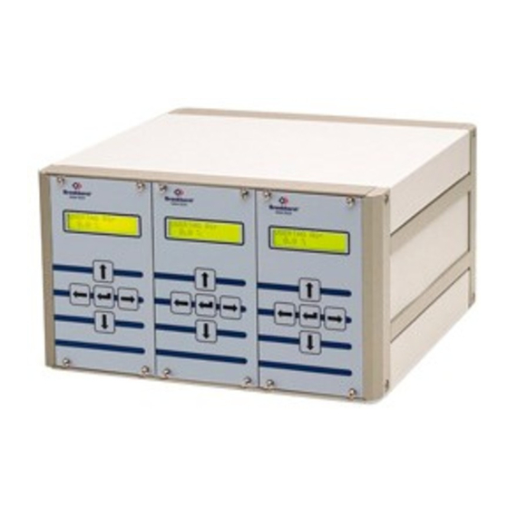
BRONKHORST HIGH-TECH B.V. 1 INTRODUCTION 1.1 General description The Bronkhorst High-Tech B.V. serie E-7000 is a modular built digital readout and control system for mass flow/pressure sensors and controllers. Basically a system consists of one or more (14TE) single channel readout/control units. - Page 8 BRONKHORST HIGH-TECH B.V. Modules with blind front (14 TE) Code Blind front only Blind front + power supply (linked to module with mains entr.) Blind front + power supply + mains entrance (incl. cable) + FLOW-BUS connection Blind front + power supply + RJ45 conn. for +15Vdc supply voltage + mains entrance (incl.
-
Page 9: Modul Configuration
BRONKHORST HIGH-TECH B.V. 1.3 Modul configuration Module X Sensor Output Input Module See table Modules, System configuration *Sensor output signal Code 0 - 5 Vdc 0 - 10 Vdc 0 - 20 mA dc (Sinking) 4 - 20 mA dc (Sinking) -
Page 10: Rear Panel Connector
Analog input signals should be connected to pin 2 (+) and 0 V/common. Analog output signals are available at pin 1 (+) and 0 V/common. Signals are according to one of the Bronkhorst HIGH-TECH B.V. standards. The model configuration contains a code, describing the input/output signals. -
Page 11: Reset Input
BRONKHORST HIGH-TECH B.V. 1.4.2.3 Reset input The reset input signal should be connected to pin 8 (+ V) and pin 3 (0 V/common). Reset can be achieved by either pulling the + V input (pin 8) to 0 V (pin 3) by means of a contact or a transistor, or by applying an active low logic signal to pin 8 (+ V) and pin 3 (0 V). -
Page 12: Connector Panel 1000 Watt Power Supply
However compliance with the EMC requirements is not possible without the use of proper cables and connector assemblies. For good results Bronkhorst HIGH-TECH B.V. can provide standard cables. Otherwise follow the guidelines as stated below. For cables with 9-pin sub D-connectors: page 12 9.17.017... -
Page 13: Readout And Control Unit Cem 120Vac / 230Vac Power Supply
BRONKHORST HIGH-TECH B.V. Fold the shield of the cable back over the cable (the shield must be around the cable). 20 mm Wind a copper tape around the shield 8 mm D-connector housing other wires Solder a black wire on the tape and... - Page 14 BRONKHORST HIGH-TECH B.V. page 14 9.17.017...
-
Page 15: Operation
BRONKHORST HIGH-TECH B.V. 2 OPERATION 2.1 Foreword This part describes the operation manual for an E7000 based R/C panel (module code 33,34,35,36 and 37). 2.2 General information Use 'cursor' keys to scroll through the menu-structure and to select the required menu level. -
Page 16: Startup And Menu Selection
BRONKHORST HIGH-TECH B.V. 2.3 Startup and menu selection page 16 9.17.017... - Page 17 BRONKHORST HIGH-TECH B.V. Menu descriptions 0001 0000 Startup screen showing company name 0002 0000 Startup screen showing communication check with FLOW-BUS in progress. Takes a short time (few seconds), depending on system size. If the FLOW-BUS address of the module is occupied, you can reinstall the module on a new address.
-
Page 18: Measure Menu
BRONKHORST HIGH-TECH B.V. 2.4 Measure menu page 18 9.17.017... - Page 19 BRONKHORST HIGH-TECH B.V. Menu descriptions 1100 0000 Stepsize editor for editing setpoint/slave-factor by a 0.1% step up or down. By holding down UP/DOWN key continuously, the step size will increase. Changes are used by the controller immediately. What is displayed here in this menu depends on the selection of the setpoint source.
-
Page 20: Operation Menu
BRONKHORST HIGH-TECH B.V. 2.5 Operation menu page 20 9.17.017... - Page 21 BRONKHORST HIGH-TECH B.V. Menu descriptions 2100 0000 Operation mode. Here you can change the source of the setpoint for the operating instrument 2110 0000 This option selects a setpoint change with the keyboard or by means of a FLOW-BUS device (operation module or Personal Computer).
-
Page 22: Reset Menu
BRONKHORST HIGH-TECH B.V. 2.6 Reset menu page 22 9.17.017... - Page 23 BRONKHORST HIGH-TECH B.V. Menu descriptions 3100 0000 Reset Alarm. Here you can reset an alarm if it is active. This will result in removing the alarm situation defined to take place at the potential free contact and/or at the (temporary) alarm setpoint. If the alarm condition is still present, the alarm will activate again after a few seconds until alarm condition is removed (temperature into save area again) or when alarm mode will be changed.
-
Page 24: Alarm Menu
BRONKHORST HIGH-TECH B.V. 2.7 Alarm menu page 24 9.17.017... - Page 25 BRONKHORST HIGH-TECH B.V. Menu descriptions 5100 0000 Alarm Reset Enable. Here you can enter which way the alarm may be reset. 5110 0000 Keyboard Reset. Here you can enable/disable an alarm reset by the keyboard. 5120 0000 External Reset. Here you can enable/disable an alarm reset by an external signal.
-
Page 26: Instrument Menu
BRONKHORST HIGH-TECH B.V. 2.8 Instrument menu page 26 9.17.017... - Page 27 BRONKHORST HIGH-TECH B.V. Menu descriptions 6100 0000 Instrument Type. Here you can change if the instrument will control or only measure temperature 6110 0000 This will only let you measure the process. You can not give setpoints. 6120 0000 This will let you control the process. You can edit the setpoint.
-
Page 28: Local Menu
BRONKHORST HIGH-TECH B.V. 2.9 Local menu page 28 9.17.017... - Page 29 7311 0000 Edit Tag. Here you can change the user tag. 7320 0000 Serial number. Here you can view the serial number of this single channel module. The Bronkhorst HIGH-TECH B.V. serial number is a unique identification for FLOW-BUS modules/ instruments.
-
Page 30: Flow-Bus Menu
BRONKHORST HIGH-TECH B.V. 2.10 FLOW-BUS menu page 30 9.17.017... - Page 31 Normally installation on the FLOW-BUS has to be performed only one time. Mostly this will be done at Bronkhorst High-Tech B.V. when your module has been built and tested. The address on the bus for this module will be stored when the module powers-off. At future power-on situations, it will be part of the FLOW- BUS on the same address each time.
-
Page 32: Calibration With Polynomial Functions
When you have 'n + 1' measure-points, they can be approximated by means of a 'n-N.D.' degree polynomial function. 2.11.3 Polynomial functions of sensor signal and setpoint By means of a calibration at Bronkhorst HIGH-TECH B.V. several measure points will be used to obtain a polynomial function. The form of this function is: = + ⋅... -
Page 33: Using Polynomial Functions At Readout/Control Unit
BRONKHORST HIGH-TECH B.V. 2.11.5 Using polynomial functions at readout/control unit The parameters for the polynomial function is stored at the readout and control-module and can be changed from the keyboard. Normally the transfer function of the sensor signal is linear Y = X. The connected device will have linearized transfer functions after (normal) calibration.The accuracy however, will be ≤...
Need help?
Do you have a question about the E-7000 Series and is the answer not in the manual?
Questions and answers