
Subscribe to Our Youtube Channel
Related Manuals for Baur Protrac


Summary of Contents for Baur Protrac
- Page 1 User manual Pin-pointing system protrac® BAUR GmbH · Raiffeisenstraße 8 · 6832 Sulz, Austria T +43 (0)5522 4941-0 · F +43 (0)5522 4941-3 · headoffice@baur.at · www.baur.eu...
-
Page 2: Table Of Contents
AGP acoustic ground probe AGP operating state indicator SVP step voltage probes Power supply Before commissioning ���������������������������������������������������������������������������������������������14 Pairing protrac® system components Pairing the AGP Pairing headphones (AGP must be switched on) Before commissioning Acoustic pin-pointing – general ����������������������������������������������������������������������������16 Basic principle... - Page 3 Pre-locating cable sheath faults more precisely Method settings Tracing – general �������������������������������������������������������������������������������������������������������27 Basic principle Required equipment User interface Performing tracing ���������������������������������������������������������������������������������������������������28 Procedure Tracing – tips, settings ���������������������������������������������������������������������������������������������30 Abrupt signal change during measurement Signal sequences Method settings Basic settings �������������������������������������������������������������������������������������������������������������32 822-186-4 protrac® pin-pointing system...
- Page 4 Why won’t the AGP or CU switch on? How do I see that a device is connected to the CU? Why are the date and time suddenly wrong? Software messages Transportation, storage, disposal ��������������������������������������������������������������������������36 Transportation Storage Disposal protrac® sets ��������������������������������������������������������������������������������������������������������������37 protrac® pin-pointing system 822-186-4...
-
Page 5: About This Manual
Applicable documents This user manual applies in conjunction with the following documents: • Data sheet of the protrac® pin-pointing system • User manuals for the cable fault location system used and for all other devices used Note on screenshots and graphics The screenshots and graphics used are intended for illustration and may differ from the actual state. -
Page 6: For Your Safety
Indicates information on the topic in the corre- sponding user manuals. Indicates required tools. Indicates required spare parts. Avoiding dangers, taking safety measures » When using protrac®, you must comply with the following regulations and guide- lines: • Local safety and accident prevention regulations •... -
Page 7: Dangers When Working With Electric Voltage
For your safety Dangers when working with electric voltage During measurements with protrac® in combination with a cable fault location system or a surge voltage generator, a dangerous – and sometimes very high – voltage is gen- erated that is fed into the test object via an HV connection cable and can produce a fatal voltage gradient near the fault location. -
Page 8: Intended Use
• Tracing If the protrac® system and its components are not used in accordance with this stipula- tion, safe operation cannot be guaranteed. The responsible body or operator is liable for any personal injury and damage to property resulting from incorrect operation. -
Page 9: After Sales Service
Intended use After Sales Service If you have any queries, please contact BAUR GmbH or your BAUR representative (http://www.baur.eu/baur-worldwide). BAUR GmbH Raiffeisenstraße 8 6832 Sulz / Austria service@baur.at www.baur.eu 822-186-4 protrac® pin-pointing system... -
Page 10: Product Information
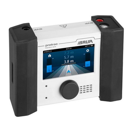
Product information System overview The protrac® system components CU control unit, AGP acoustic ground probe and headphones are wirelessly connected together via Bluetooth®. CU control unit Brightness sensor for the automatic adjustment of the touchscreen brightness LED for the operating state indicator [Ü... -
Page 11: Cu Control Unit
Bluetooth®, rechargeable and non-rechargeable battery status of the control unit Acoustic pin-pointing Sheath fault location Tracing Basic settings The CU is switched off automatically if there is no connection to an AGP or to the SVPs for 5 minutes. 822-186-4 protrac® pin-pointing system... -
Page 12: Cu Operating State Indicator
CU operating state indicator The LED on the CU indicates the following operating states: • (flashing): The CU is in pairing mode. [Ü “Pairing protrac® system components”] • (permanently on): The CU is switched on and paired to the Bluetooth® devices. •... -
Page 13: Agp Operating State Indicator
To adjust the height of the SVPs: » Press the button (1) in the recess on the handle and set the desired height. Power supply protrac® is supplied with power from rechargeable or non-rechargeable batteries: • Rechargeable battery type: NiMH Mignon 1.2 V IEC LR6 •... -
Page 14: Before Commissioning
Before commissioning Pairing protrac® system components If an AGP or headphones are subsequently integrated into a protrac® system, so-called pairing must be performed. To do this, the devices are paired with the CU via Blue- tooth® the first time they are used. This procedure need only be performed once, after which the connection is established automatically. -
Page 15: Before Commissioning
3. Verify absence of operating voltage. 4. Earth and short all phases. 5. Provide protection against adjacent live parts. 6. Shield all metal parts near the cable route. » Follow the user manuals for all devices used. 822-186-4 protrac® pin-pointing system... -
Page 16: Acoustic Pin-Pointing - General
The shorter the measured time, the closer is the acoustic ground probe to the fault. Required equipment • Surge voltage generator (e.g. BAUR SSG) • CU control unit, AGP acoustic ground probe, Bluetooth® headphones protrac® pin-pointing system... -
Page 17: User Interface
Indicates the strength of the acoustic signal (incl. last measured peak level) Shows the cable route (light stripe in the middle) and neighbouring zones, and where you are located in rela- tion to the cable route (blue directional arrow) 822-186-4 protrac® pin-pointing system... -
Page 18: Performing Acoustic Pin-Pointing
Settings > Sound > Volume [Ü “Basic settings”]. 10. If you wish to use the loudspeaker of the CU instead of the headphones, make the following selection on the home screen: Settings > Sound > Output [Ü “Basic settings”]. protrac® pin-pointing system 822-186-4... - Page 19 13. To change the settings, call up the method settings by tapping 14. Move along the cable route towards the fault with the AGP. 15. Once you have located the fault, mark the position. 16. Switch the devices off. 822-186-4 protrac® pin-pointing system...
-
Page 20: Acoustic Pin-Pointing - Tips, Settings
Tips Evaluation of the acoustic and electromagnetic signals For acoustic pin-pointing using protrac®, the propagation times of the acoustic and electromagnetic signals are compared (coincidence method). This is helpful, for exa- mple, for cables laid in pipes or under concrete: The acoustic signal is often loudest at the end of a pipe or concrete slab, which can be misleading. -
Page 21: Method Settings
Note: You can change the gain during pin-pointing by tapping the bar. Ambient noise sup- Is used to activate and deactivate the pression ambient noise suppression Basic settings Calls up the basic settings for protrac® 822-186-4 protrac® pin-pointing system... -
Page 22: Sheath Fault Location - General
The step voltage that can be measured on the earth sur- face, rises in the direction of the fault and changes the polarity directly above the fault. Required equipment • HV generator (e.g. BAUR shirla) • CU control unit, SVP step voltage probes •... -
Page 23: Performing Sheath Fault Location
Example: Connect HV source to 3-phase cable (no earthing strip laid) HV source 2. Switch on the HV source and set the output voltage. 3. Switch on the high voltage on the HV source. 822-186-4 protrac® pin-pointing system... - Page 24 Right above the fault, the polarity of the voltage changes. If the SVPs are inserted symmetrically above the fault, the deflection of the bar graph is zero. 14. Once you have located the fault, mark the position. 15. Switch the devices off. protrac® pin-pointing system 822-186-4...
-
Page 25: Sheath Fault Location - Tips, Settings
Two cable sheath faults Pre-locating cable sheath faults more precisely » To pre-locate the cable sheath faults more precisely, perform a Glaser measuring bridge measurement. Follow the instructions in the user manual for the bridge measuring unit. 822-186-4 protrac® pin-pointing system... -
Page 26: Method Settings
Voltage indicator Is used to set whether the voltage indi- cator is adjusted automatically ( ) or manually ( Basic settings Calls up the basic settings for protrac® protrac® pin-pointing system 822-186-4... -
Page 27: Tracing - General
Tip: for clear signal detection, use the active tracing method. Required equipment • Audio frequency transmitter (e.g. BAUR TG) • CU control unit, AGP acoustic ground probe, Bluetooth® headphones •... -
Page 28: Performing Tracing
3. Position the AGP on the ground with the directional arrow in the direction of the cable route. 4. Switch on the AGP, the headphones and the CU. The header of the touchscreen shows that the devices are connected. protrac® pin-pointing system 822-186-4... - Page 29 Minimum method: If the AGP is moved towards the cable route, the blue bar gets lower and, depending upon the setting, the acoustic signal either becomes quieter or lower. 11. Mark the course of the cable route with the markers. 12. Switch the devices off. 822-186-4 protrac® pin-pointing system...
-
Page 30: Tracing - Tips, Settings
• a nodal point at which the signal is distributed in several directions • a cable or screen break • a cable loop • a fault due to earth contact Signal sequences Maximum method Minimum method protrac® pin-pointing system 822-186-4... -
Page 31: Method Settings
• Automatic : The gain is automatically set to the optimal level in accordance with the selected method. • Manual : You can enter the gain for each AGP coil yourself. Basic settings Calls up the basic settings for protrac® 822-186-4 protrac® pin-pointing system... -
Page 32: Basic Settings
Is used to set the volume and whether output is via headphones or loudspeaker The volume can also be limited to 85 dB(A) (applies only for BAUR headphones from the standard delivery). AGP mute Is used to adjust how sensitive the automatic... - Page 33 Is used to set the date and time displayed on the CU About Displays the current software versions of the CU, the AGP and the Sheath fault location module. Factory set- Resets the CU back to factory settings tings 822-186-4 protrac® pin-pointing system...
-
Page 34: Questions And Answers
» Switch the device on. • The device has not yet been paired with the CU. » Pair the device with the CU [Ü “Pairing protrac® system components”]. • There is a Bluetooth® connection problem. » Re-establish the Bluetooth® connection [Ü... -
Page 35: Software Messages
No AGP The AGP is not switched on. connected » Switch on the AGP. The rechargeable or non-rechargeable batteries of the AGP are too weak. » Charge or replace the rechargeable batteries, or replace the non-rechargeable batteries. 822-186-4 protrac® pin-pointing system... -
Page 36: Transportation, Storage, Disposal
CU and AGP approximately every 2 months. Disposal BAUR devices do not belong in the domestic waste. » Dispose of the devices and rechargeable and non-rechargeable batteries in an environmentally friendly manner and in accordance with the applicable national regulations. -
Page 37: Protrac® Sets
Complete set "Acoustics" set “Step voltage” set 822-186-4 protrac® pin-pointing system... - Page 38 Notes protrac® pin-pointing system 822-186-4...
- Page 39 Notes 822-186-4 protrac® pin-pointing system...
- Page 40 BAUR GmbH Raiffeisenstraße 8 6832 Sulz / Austria headoffice@baur.at www.baur.eu 822-186-4-TR-21.02.2019...
Need help?
Do you have a question about the Protrac and is the answer not in the manual?
Questions and answers