Table of Contents
Advertisement
Quick Links
www.orioncontrols.com
VCM-X Controller Code: SS1026 & Y200920 Version 2.0 and up;
VCM-X WSHP Controller Code: SS1032 & SS1033
VCM Controller Code: SS1016, Y200409, Y200616, Y200822
PT-Link II N2-3
Technical Guide
www.orioncontrols.com
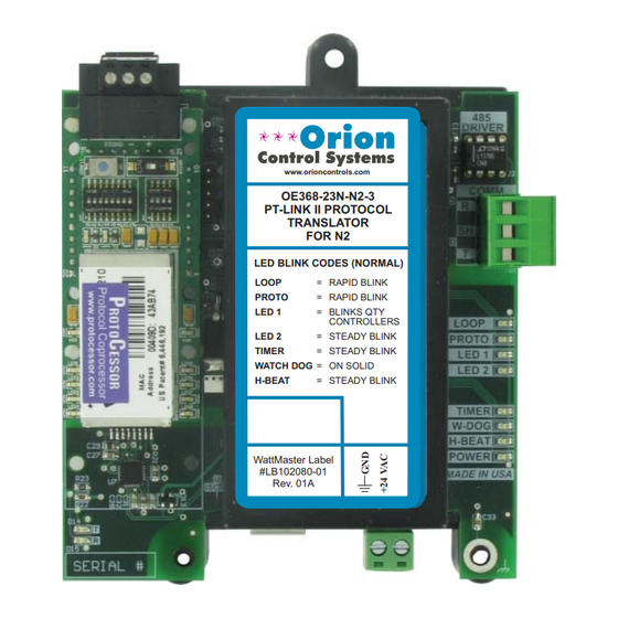
OE368-23N-N2-3
PT-LINK II PROTOCOL
TRANSLATOR
FOR N2
LED BLINK CODES (NORMAL)
LOOP
= RAPID BLINK
PROTO
= RAPID BLINK
LED 1
= BLINKS QTY
CONTROLLERS
LED 2
= STEADY BLINK
TIMER
= STEADY BLINK
WATCH DOG
= ON SOLID
H-BEAT
= STEADY BLINK
WattMaster Label
#LB102080-01
Rev. 01A
SA Controller Code: Y200921
®
Advertisement
Table of Contents

Summary of Contents for Orion Control Systems PT-Link II N2-3
- Page 1 PT-Link II N2-3 ® Technical Guide VCM-X Controller Code: SS1026 & Y200920 Version 2.0 and up; VCM-X WSHP Controller Code: SS1032 & SS1033 SA Controller Code: Y200921 VCM Controller Code: SS1016, Y200409, Y200616, Y200822 www.orioncontrols.com OE368-23N-N2-3 PT-LINK II PROTOCOL...
-
Page 2: Table Of Contents
Table of Contents General Information ............................3 Hardware Specifi cations ................................3 System Requirements ..................................3 Dimensions and Components ..............................4 Quick Start Guide ............................4 Connection and Wiring Information ........................ 5 Confi guring the PT-Link II Controller ....................... 6 PT-Link II Hardware Connection ..............................6 Computer IP Address Set-up for Windows NT &... -
Page 3: General Information
PT-Link II N2-3 Technical Guide ® General Information Scheduling ® The OE368-23N-N2-3, PT-Link II N2-3 provides bi-directional com- ® munication between your N2 MS/TP protocol network and up to four* of any of the following types of Orion controllers—VCM-X, SA, VCM, •... -
Page 4: Dimensions And Components
H-BEAT POWER Power Ethernet WattMaster Label MADE IN USA #LB102080-01 Port Rev. 01A 0.27 2.61 0.20 Dia. Mounting Hole Typ. 4 PL. 24 VAC Power Terminal Port ® Figure 1: PT-Link II N2 Dimensions and Components PT-Link II N2-3 Interface... -
Page 5: Connection And Wiring Information
Line Voltage Line Voltage electrical codes and specifications. 2.) All communication wiring to be 18 gauge minimum, 2 conductor twisted pair with shield. Use Belden #82760 or equivalent. ® Figure 2: PT-Link II N2 Interface Wiring PT-Link II N2-3 Interface... -
Page 6: Confi Guring The Pt-Link Ii Controller
LED 2 = STEADY BLINK TIMER = STEADY BLINK WATCH DOG = ON SOLID H-BEAT = STEADY BLINK WattMaster Label #LB102080-01 Rev. 01A Connect Ethernet Crossover Cable To PT-Link Ethernet Port Figure 3: Connecting With Crossover Cable PT-Link II N2-3 Interface... -
Page 7: Computer Ip Address Set-Up For Windows Nt & Xp
5). As shown in Figure 6, in the Connection Items list box, be sure the Internet Protocol (TCP/IP) is checked. Select the Internet Protocol (TCP/IP) item to highlight it and then click <Properties> . The Internet Protocol Properties Window will appear. PT-Link II N2-3 Interface... -
Page 8: Computer Ip Address Set-Up For Windows Vista, 7, Or 8
You may have to reboot the computer windows are closed. You may have to reboot the computer before the new values are valid. before the new values are valid. PT-Link II N2-3 Interface... -
Page 9: Connecting To The Pt-Link Ii Using Field Server's Graphical User Interface
So, although technical functionality is operational, the looks might be slightly different FS-GUI Reference Guide An FS-GUI Reference Guide can be found in Appendix A, page 22. Figure 9: Navigation Window - File Transfer PT-Link II N2-3 Interface... - Page 10 Only edit the confi g.csv fi le using Notepad. DO NOT use Excel. Using Excel to edit the confi g.csv fi le will corrupt its contents! Figure 11: Confi g.csv File Figure 13: Update Confi guration PT-Link II N2-3 Interface...
- Page 11 1. ) In the Navigation Window on the left of the FS-GUI Main Screen, <View> <Data Arrays> controller type. These tables can be found on pages 19-21. click and then click . See Figure 14. Figure 14: Navigation Window - View Data Arrays PT-Link II N2-3 Interface...
-
Page 12: Troubleshooting The Pt-Link Ii Controller
AHU Controller Address Node_ID Virtual N2 Device Address NOTE: To simplify the calculation, we recommend that the Watt- Master controls be addressed in sequential order from one to the last control without any unused address(es) in between. PT-Link II N2-3 Interface... -
Page 13: Pt-Link Ii Board Leds
Protocessor is installed correctly and fi rmly connected to the Base Board. The “PWR” LED should also be lit on the Protocessor Module. TIMER LED The “TIMER” is used for troubleshooting by WattMaster Controls Technical Support. The “TIMER” LED should always have a steady blink. PT-Link II N2-3 Interface... -
Page 14: Protocessor Module Leds - Oe368-23N-N2-3
NOTE: If all of these tests are made and the controller still doesn’t operate, please contact WattMaster Controls Technical Support at our Toll Free number—866-918-1100—for assistance. Figure 17: PT-Link II N2-3 ® LED Locations ® Figure 18: PT-Link II N2-3... -
Page 15: Updating The Pt-Link Ii Controller
Prism program. <Job-Site> 7.) Click on the icon. The Job-Sites Window will appear. In the Type of CommLink Dialog Box, select “Hi Speed CommLink.” PT-Link II N2-3 Interface... - Page 16 Now, cycle power to the PT-Link II once again and within 5 <Program HEX> seconds click on the button (shown above). If suc- cessful, you should see the Progress Application HEX bar showing the progress percentage. PT-Link II N2-3 Interface...
- Page 17 You will need to know this when setting up the Prism software. If the COM port number is 10 or greater, go to “Changing the USB COM Port Number” on page 18. <Hardware> Click the tab. <Device Manager> Click the button. PT-Link II N2-3 Interface...
- Page 18 Once you select the correct COM port number, click <Port Settings> tab. <OK> and close any windows opened in the process of changing the port number. Make note of this number because you will need it for your Prism setup. PT-Link II N2-3 Interface...
-
Page 19: Data Arrays
RaDmp RfPr OaDwpt CoilTp SaTpStM PreHtSp OaCFM EtCFM SaCFM OACfmSt OACfmRs OACfmStM MdCmp2 HdPr1 HdPr2 CdFan1 CdFan2 WaterTpA A1LSPAlm A1LktAlm B1LSPAlm B1LktAlm LWT1Alm POWF1Alm ComMAlm RmVFDPos Table 3: VCM-X WSHP (Coil) Data Array For Field Server PT-Link II N2-3 Interface... - Page 20 EaTp EwTp EaRH HdPr1 HdPr2 CoilTp2 EaDpt WSEByp WSEByp2 MdCmp2 CoilTpSt CdPos1 CdPos2 EaTpAlm EmerAlm PoWFAlm DrnAlm EaTpOst EwTpOst – – – – – – – – Table 5: SA Controller Data Array For Field Server PT-Link II N2-3 Interface...
- Page 21 ExRly5 ExRly6 ExRly7 ExRly8 ExRly9 ExRly10 ExRly11 ExRly12 ExRly13 ExRly14 ExRly15 ExRly16 CO2St MinEcoSt CO2Level ByPasDmp RaDmp RfPr OaDwpt CoilTp SaTpStM PreHtSp – – – – – – Table 6: VCM Data Array For Field Server PT-Link II N2-3 Interface...
-
Page 22: Appendix A - Fieldserver's Graphical User Interface Reference Guide
Press this button to return to FS-GUI Main Screen. displayed on this screen. These messages convey protocol specifi c information that can be useful for fi eld integration purposes. Combined Screen —This screen contains all messages chronologi- cally from all the above message screens. PT-Link II N2-3 Interface... - Page 23 . See Figure 23. The Passwords Settings> Window will appear. NOTE: The only time you should change the IP address is during the initial confi guration and/or during trouble- shooting. Figure 23: Setup - Passwords Figure 22: Network Settings Window PT-Link II N2-3 Interface...
- Page 24 Admin Password fi eld and leaving the last two fi elds Figure 28: Changing the User Password <Update Password> blank. Then click See Figure 26. 7.) If the user password update is successful, a message will pop up confi rming the password update. PT-Link II N2-3 Interface...
-
Page 25: Appendix B - Vcm-X Wshp N2 Parameters
Compressor A1 A1LktAlm BI: 223 Alarm that Proof of Water 1 POWF1Alm BI: 232 Alarm that indi- Lockout Alarm indicates Flow Alarm cates no Proof of Compressor A1 Water Flow for is locked out. System A (A1/ PT-Link II N2-3 Interface... - Page 26 Low Suction indicates Pressure Alarm Suction Pressure for Circuit A is below the Low Suction Pres- sure Cooling (Heating) Setpoint. Compressor A A1LktAlm BI: 223 Alarm that Lockout Alarm indicates Circuit A Com- pressors are locked out. PT-Link II N2-3 Interface...
-
Page 27: Appendix C - Vcm-X N2 Parameters
ExRlys12 AI: 111 Needed only in Outdoor Air OaWtbl AI: 55 Current calculated Relays 1-2 legacy application. Wetbulb value of the out- door wetbulb External ExRlys34 AI: 112 Needed only in temperature. Relays 3-4 legacy application. PT-Link II N2-3 Interface... - Page 28 Setpoint will activate the this option to enter cooling demand. an offset If the control temperature to temperature is the adjust the Sensor’s Supply Air Sensor, Temperature. then the cooling demand is always active. PT-Link II N2-3 Interface...
- Page 29 200 K amount. If you do CFM Reset Outdoor Air CFM not want Cooling to Limit when CO reaches operate during the its reset limit. Unoccupied Mode, use the default setting of 30°F for these setpoints. PT-Link II N2-3 Interface...
- Page 30 REHEAT II Rt2Ins BI: 58 Status that indicates Connected the MHGRV Space SpcTpAlm BI: 101 Alarm that indicates controllers is Temperature a failure in the connected to the Sensor Lost space temperature system. sensor. PT-Link II N2-3 Interface...
- Page 31 VcmxOnBoardRelaysBits ::= BIT STRING { Expansion ExRly15 BI: 147 Current status of OnBoardRelay1 (0), Relay 15 relay 20. OnBoardRelay2 (1), Expansion ExRly16 BI: 148 Current status of OnBoardRelay3 (2), Relay 16 relay 21. OnBoardRelay4 (3), OnBoardRelay5 PT-Link II N2-3 Interface...
- Page 32 VcmxAlarmGroup3Bits ::= BIT STRING { ExpansionBoard3Relay3 (2), LowSupplyAirTempAlarm (0), ExpansionBoard3Relay4 (3), HighSupplyAirTempAlarm (1), ExpansionBoard4Relay1 (4), LowControlTempAlarm (2), ExpansionBoard4Relay2 (5), HighControlTempAlarm ExpansionBoard4Relay3 (6), ExpansionBoard4Relay4 VcmxAlarmStatusBits ::= BIT STRING { Alarm Group1 (0), Alarm Group2 (1), Alarm Group3 PT-Link II N2-3 Interface...
- Page 33 Humidity the Entering Air. Current calculated SAT setpoint with Coil CoilTp2 AI: 240 Current Coil Reset Source. Temperature Temperature for 2nd unit. Supply Air SaTp AI: 83 Current value of the Temperature supply air temperature sensor. PT-Link II N2-3 Interface...
-
Page 34: Appendix D - Sa Controller N2 Parameters
Sensor’s Temperature. SaClSt AO: 77 Supply Air Setpoint Cooling in Cooling Mode. Setpoint SaHtSt AO: 78 Supply Air Setpoint Heating in Heating Mode. Setpoint PT-Link II N2-3 Interface... - Page 35 Supply Air Temperature temperature to Alarm has not fallen 5°F w/in a user- adjust the adjustable time period. This does Sensor’s not indicate compressors are Temperature. active and will not shut the unit down. PT-Link II N2-3 Interface...
- Page 36 Current status of relay 12. Relay 7 Expansion ExRly8 BI: 140 Current status of relay 13. Relay 8 Expansion ExRly9 BI: 141 Current status of relay 14. Relay 9 Expansion ExRly10 BI: 142 Current status of relay 15. Relay 10 PT-Link II N2-3 Interface...
-
Page 37: Appendix E - Vcm N2 Parameters
Outdoor Air OaWtbl AI: 55 Current calculated value Position heating signal Wetbulb of the outdoor wetbulb (hot water or SCR temperature. heat). Relief RfPr AI: 62 Current value of the Pressure building pressure sensor. PT-Link II N2-3 Interface... - Page 38 Supply Air setpoint Setpoint the control will Source or Reset Source activate the cooling Heating target temperature demand. If the Setpoint in Heating Mode. control temperature is the Supply Air Sensor, then the cooling demand is always active. PT-Link II N2-3 Interface...
- Page 39 HtDmnd BI: 29 Status that indicates mode. Produces Demand a demand for dewpoint in the heating. supply air Heating HtEnbl BI: 30 Status that approximately Enabled indicates that 10°F above this mechanical heating setpoint. is enabled. PT-Link II N2-3 Interface...
- Page 40 Relay 2 relay 7. shut the unit down. Expansion ExRly3 BI: 135 Current status of Dirty Filter DrtFlAlm BI: 96 Alarm that indicates Relay 3 relay 8. Detected the fi lters are dirty. PT-Link II N2-3 Interface...
- Page 41 PurgeModeActive (10) Relay 15 relay 20. Expansion ExRly16 BI: 148 Current status of Relay 16 relay 21. VcmControlStatusBits ::= BIT STRING { AhuControlEconomizer (0), NoOutdoorAirTempSensor (1), CarbonDioxideSensorPresent (2), HeatCoolStagingDisabled (3), Dehumidifi cationMode (4), ModGasIIConnected (5), ReheatIIConnected PT-Link II N2-3 Interface...
- Page 42 DirtyFilterDetected (3), ExpansionBoard2Relay4 SmokeDetected VcmExternal Relays2-4Bits::= BIT STRING { VcmAlarmGroup3Bits ::= BIT STRING { ExpansionBoard3Relay1 (0), LowSupplyAirTempAlarm (0), ExpansionBoard3Relay2 (1), HighSupplyAirTempAlarm (1), ExpansionBoard3Relay3 (2), LowControlTempAlarm (2), ExpansionBoard3Relay4 (3), HighControlTempAlarm ExpansionBoard4Relay1 (4), ExpansionBoard4Relay2 (5), ExpansionBoard4Relay3 (6), ExpansionBoard4Relay4 PT-Link II N2-3 Interface...
- Page 43 PT-Link II N2-3 Technical Guide ® Notes PT-Link II N2-3 Interface...
- Page 44 Form: OR-PTLNK3N2-TGD-01E Printed in the USA October 2016 All rights reserved. Copyright 2016 WattMaster Controls, Inc. 8500 NW River Park Drive Parkville, MO 64152 Phone (816) 505-1100 www.orioncontrols.com Fax (816) 505-1101...
Need help?
Do you have a question about the PT-Link II N2-3 and is the answer not in the manual?
Questions and answers