Table of Contents
Advertisement
Quick Links
ChipBLASTER, Inc
HIGH PRESSURE / HIGH VOLUME COOLANT DELIVERY SYSTEM
INSTALLATION, OPERATION and SERVICE
ChipBLASTER, Inc.
13605 South Mosiertown Road
Meadville, PA 16335
USA
www.chipblaster.com
Telephone
814-724-6278
Fax
814-724-6287
For your records please list serial number from nameplate ______________
D30-80-1
FIXED VOLUME MODELS
STANDARD AND
STATEMENT NUMBER 00-10-005
MANUAL
P/N: MAN-D3001
CERTIFIED
.
REV K
Advertisement
Table of Contents
Troubleshooting

Summary of Contents for ChipBLASTER STANDARD UNIT D30-80-1
- Page 1 P/N: MAN-D3001 ChipBLASTER, Inc D30-80-1 FIXED VOLUME MODELS HIGH PRESSURE / HIGH VOLUME COOLANT DELIVERY SYSTEM STANDARD AND CERTIFIED STATEMENT NUMBER 00-10-005 INSTALLATION, OPERATION and SERVICE MANUAL ChipBLASTER, Inc. 13605 South Mosiertown Road Meadville, PA 16335 www.chipblaster.com Telephone 814-724-6278 814-724-6287...
- Page 2 ChipBLASTER Inc REVISION RECORD REVISION DATE PERSON DESCRIPTION OF CHANGE 02 MAR 2006 NEW RELEASE 17MAR06 ADDED MORI CABLES 31 MAR 2006 DWG REV SECT 21.0. 5 APR. 06 R.B. DWG. REV. PAGE 42 19 MAY 2006 R.B. ADDED PAGE 25 (CHECKING...
- Page 3 ChipBLASTER Inc GENERAL: This manual covers the following ChipBLASTER model: D30-80-1 - STANDARD UNIT (60Hz) For the model number of your unit refer to the data nameplate located on the enclosure door. UNIT MODEL NUMBER UNIT SERIAL NUMBER DATA NAME PLATE...
- Page 4 ChipBLASTER Inc GENERAL: This manual covers the following ChipBLASTER model: D30-80-1 - CE CERTIFIED UNIT (50Hz) For the model number of your unit refer to the data nameplate located on the enclosure door. DATA NAME PLATE UNIT MODEL NUMBER UNIT SERIAL NUMBER...
-
Page 5: General Warnings
ChipBLASTER Inc 1.0. GENERAL WARNINGS: Thank you for purchasing a ChipBLASTER high-pressure coolant system. For reliable, safe and long term operation of your ChipBLASTER: Machine must be installed and connected to electric service per the installation portion of this manual. -
Page 6: Table Of Contents
Page 9 Explanation of markings Section 4.1 Page 9 Storage Section 5.0 Page 14 Moving machine Section 6.0 Page 14 Placing a ChipBLASTER Section 7.0 Page 15 Mechanical installation Section 8.0 Page 16 Electrical installation Section 9.0 Page 17 Power Interface Section 9.1... - Page 7 ChipBLASTER Inc 2.0. Table of Contents (Cont.): Return pump - Check for leaks Section 14.30 Page 33 Return pump - Check inlet and outlet Section 14.31 Page 33 Troubleshooting Section 15.0 Page 34 Troubleshooting flow chart (Figure 3) Section 15.1...
-
Page 8: Specifications
ChipBLASTER Inc. also reserves the right to change the contents of this manual without notice. If you have any questions please contact... -
Page 9: Safety Precautions
The items described in these instructions are very important, so that you can use the ChipBLASTER safely, prevent injury to yourself and other people around you as well as prevent damage to property in the area. Thoroughly familiarize yourself with the symbols and indications shown below and then continue to read the manual. - Page 10 ChipBLASTER Inc 4.1. EXPLANATION of MARKINGS (Cont.): Symbols (Cont.) Meaning of Symbols Mandatory Indicates something mandatory (must be done). What is mandatory will be described in or near the symbol in either text or picture form. PINCH POINT Any point where lids or covers may pinch fingers.
- Page 11 When removing filter bags or working on equipment, safety glasses must be worn to prevent injury from splashing fluid or from other hazards. MACHINE STARTS AUTOMATICALLY ChipBLASTER equipment will start without operator input. Do not remove any guards or covers until disconnect switches are shut off, locked out and tagged.
- Page 12 ChipBLASTER Inc 4.1. EXPLANATION of MARKINGS (Cont.): Symbols (Cont.) Meaning of Symbols (Cont.) NO ACCESS FOR UNAUTHORIZED PERSONS Do not open electrical enclosures or remove any guards if you have not been trained or do not have knowledge of the equipment.
- Page 13 ChipBLASTER Inc 4.1. EXPLANATION of MARKINGS (Cont.): Meaning of Symbols (Cont.) Symbols (Cont.) WEAR SAFETY GLOVES When changing filter bags it is recommended to wear safety gloves to protect hands from metal chips and the coolant that may be used in the machine.
-
Page 14: Storage
ChipBLASTER Inc 5.0. STORAGE: If the ChipBLASTER is to be stored for any period of time it must be keep in an area that is protected from freezing. Freezing temperatures will damage the pumps and the valves. Keep ChipBLASTER covered until ready to move to site. If MistBLASTER is also supplied keep covered. -
Page 15: Placing A Chipblaster
7.2.1. Remove the lumber that is used to hold the unit in place during transporation using a phillips screw driver or an electric screw gun. 7.2.2. Before you remove the ChipBLASTER from the skid take a moment to locate the bags containing the casters. -
Page 16: Mechanical Installation
ChipBLASTER Inc 7.0. PLACING A ChipBLASTER (Cont.): After ChipBLASTER is in place and level, locate all ship loose items. Ship loose items include: high pressure hose with adapter fitting, low pressure hose and low pressure hose clamps. Place all hoses at the front of the unit (same end as enclosure). -
Page 17: Electrical Installation
DISCONNECT AND LOCKOUT / TAGOUT ALL ELECTRICAL ENERGY SOURCES *NOTE-The ChipBLASTER is equipped to accept control interface voltages of 120vac or 24vdc. Please make sure the appropriate control voltage relay is installed in CR1 & CR3 of the unit. The unit is shipped from the factory with 120vac relays installed in CR1 &... -
Page 18: Start Up
Or (if using the 12 pin power & control interface plug) wire to pins 10/11 or 10/12. ES is the ChipBLASTER error signal. NOTE: Machine tool damage could result if the ES signal is not properly interfaced! *NOTE - THE ES RELAY IS DE-ENERGIZED WHEN THE ChipBLASTER IS OPERATING WITHOUT ERROR. - Page 19 Close the thumb screws. 11.1.3 Start the Chipblaster and check for any coolant leaks. 11.1.4 Insure that all electrical circuits are operating correctly. 11.1.5 The coolant outlet pressure is factory preset to run at 1000 PSIG (69 bar), or a...
-
Page 20: Operation
“M” code from the machine tool. The low pressure, as supplied from the factory, is available at coolant outlet number 1 and/or 2, depending on ChipBLASTER model. The low pressure flood is used to flush parts, tool plates and general chip clearing. -
Page 21: Coolant Flow Diagram (Figure 1)
ChipBLASTER Inc 12.0. OPERATION (Cont.): 12.3. COOLANT FLOW DIAGRAM (Figure 1): Figure 1 12.3... -
Page 22: Alarms
(switch selector valve to clean filter or replace dirty filter cartridge). Note: power to unit must be cycled off/on to reset the ES relay circuit. Re-energize the required “M” code to start the ChipBLASTER. 14.0. PREVENTATIVE MAINTENANCE: DO NOT ATTEMPT ANY SERVICE ON ChipBLASTER UNIT WITH POWER ENERGIZED. - Page 23 ChipBLASTER Inc 14.0. PREVENTATIVE MAINTENANCE (Cont.): 14.1. PREVENTATIVE MAINTENANCE SCHEDULE (Figure 2): 14.1...
-
Page 24: High-Pressure Pump
Oil Fill Cap/Dipstick “ADD” Mark “FULL” Mark FAILURE TO USE MOBIL 1 FULLY-SYNTHETIC 15W-50 WILL VOID YOUR WARRANTY DO NOT ATTEMPT ANY SERVICE ON ChipBLASTER UNIT WITH POWER ENERGIZED. REMOVE ALL ENERGY SOURCES AND LOCK OUT / TAG OUT. 14.2... - Page 25 14.3.2. The oil level must be maintained between the full and add marks. If required add oil (refer to Section 14.3.6.). FAILURE TO USE MOBIL 1 FULLY-SYNTHETIC 15W-50 WILL VOID YOUR WARRANTY DO NOT ATTEMPT ANY SERVICE ON ChipBLASTER UNIT WITH POWER ENERGIZED. REMOVE ALL ENERGY SOURCES AND LOCK OUT / TAG OUT. 14.2...
-
Page 26: Oil Change Procedure
IT IS EXTREMELY IMPORTANT TO DISCONNECT AND LOCKOUT ANY AND ALL POWER SOURCES BEFORE ANY WORK IS TO BE PERFORMED ON the ChipBLASTER UNIT. 14.3.1. ChipBLASTER High-Pressure Pump: Change the crankcase oil after every 2000 hours of operation. USE: Mobil 1 fully synthetic 15W-50 oil. - Page 27 ChipBLASTER Inc 14.0. PREVENTATIVE MAINTENANCE (Cont.): 14.3. OIL CHANGE PROCEDURE (Cont.): 14.3.5. After oil is drained from pump reinstall the plug in back of pump. Torque to 20 Nm (180 In LB). PROPERLY DISPOSE OF OIL PER LOCAL REGULATIONS. DO NOT REUSE OIL.
- Page 28 14.3.11. Reinstall right side panel. Tighten BHCS to 12 Nm (106 In Lb). DO NOT RUN HIGH PRESSURE PUMP WITHOUT OIL AS DAMAGE WILL RESULT AND VOID YOUR WARRANTY. DO NOT ATTEMPT ANY SERVICE ON ChipBLASTER UNIT WITH POWER ENERGIZED. REMOVE ALL ENERGY SOURCES AND LOCK OUT / TAG OUT.
-
Page 29: High Pressure Pump - Check Belt
RGA number for the pump to be replaced. 14.6.2. When the old pump is received at ChipBLASTER, the pump will be inspected for any damage. If no damage is noted a core charge credit will be issued. - Page 30 DUE TO THE CHIPS THAT MAY BE IN THE FILTERS. 14.14. DUAL MANUAL FILTER: (CHIPBLASTER SHUT DOWN) The preferred method is to shut down the ChipBLASTER. 14.14.1. A dirty filter error signal to alarm horn/machine center or a 1 bar (15 psi), or less, pressure reading on the filter outlet pressure gauge will indicate when the cartridge filter is dirty.
- Page 31 ChipBLASTER Inc 14.0. PREVENTATIVE MAINTENANCE (Cont.): 14.15. DUAL MANUAL FILTER: (CHIPBLASTER OPERATING) EXERCISE EXTREME CAUTION WHEN CHANGING THE FILTER CARTRIDGE WHILE THE MACHINE IS IN OPERATION. ENSURE THAT THE SELECTOR BALL VALVE IS POSITIONED TO DESIRED FILTER TO PREVENT COOLANT FROM FLOWING THROUGH THE FILTER THAT IS BEING SERVICED.
-
Page 32: Filter Replacement Form
ChipBLASTER Inc 14.0. PREVENTATIVE MAINTENANCE (Cont.): 14.16. FILTER REPLACEMENT FORM PLEASE MAKE A COPY OF THE FILTER REPLACEMENT FORM BEFORE ORDERING. 14.16... -
Page 33: Filter Assemblies - Check For Leaks
14.29.2. An indication the return pump may be clogged will be constant low pressure at the filter inlet 14.29.3. The ChipBLASTER must be powered down and the disconnect placed in the OFF position and locked out. 14.29.4. Remove the inlet and outlet hoses by loosening the hose clamps. Inspect the inlet and outlet for chips that may have accumulated. -
Page 34: Troubleshooting
ChipBLASTER Inc 15.0. TROUBLESHOOTING: Fault Symptom Cure ChipBLASTER has no power Disconnect switch is off Turn on disconnect 1DS Control Relay CR1 not energizing No command voltage from machining center Check command voltage Faulty relay Replace relay Main pump motor not operating... -
Page 35: Troubleshooting Flow Chart (Figure 3)
DETERMINE THE CAUSE AND CORRECT! FOR ADDITIONAL INFORMATION PLEASE CONTACT ChipBLASTER SERVICE DEPARTMENT AT (814) 724-6278. WHEN CONTACTING ChipBLASTER SERVICE DEPARTMENT PLEASE HAVE MODEL AND SERIAL NUMBER OF YOUR ChipBLASTER UNIT. 15.1. TROUBLESHOOTING FLOW CHART (Figure 3): DO YOU HAVE CORRECT PRESSURE AT... -
Page 36: Pressure Adjustment Procedure
69 Bar (1000 psi), unless otherwise specified by the end user. This pressure can be read from the high pressure gauge located on the top of the ChipBLASTER unit. Check the machine tool specifications for a maximum operating pressure before proceeding with this procedure. -
Page 37: High Pressure Pump Replacement
ChipBLASTER Inc 17.0. HIGH PRESSURE PUMP REPLACEMENT: IT IS EXTREMELY IMPORTANT TO DISCONNECT AND LOCKOUT ANY AND ALL POWER SOURCES BEFORE ANY WORK IS TO BE PERFORMED ON THE ChipBLASTER UNIT! 17.1. LUBRICATION After pump replacement procedure, check to ensure that the replacement pump crankcase contains oil, and is at the proper level. -
Page 38: Belt Installation
ChipBLASTER Inc 18.0. BELT INSTALLATION: 18.1. Align Sprockets: 18.1.1. Sprocket alignment and parallelism of the shafts is very important. Proper alignment helps to equalize the load across the entire belt width, thereby reducing wear and extending belt life. The sketches below show how to align a Synchronous drive properly. - Page 39 ChipBLASTER Inc 18.0. BELT INSTALLATION (Cont.): 18.3.1.2. Increase the belt tension until the belt feels snug or taut. Avoid over tensioning the belt. 18.3.1.3. Start the drive and apply the most severe load condition. This may be either the motor starting torque or during the work cycle. A belt that is too loose will “jump teeth"...
-
Page 40: Deflection Force Chart
ChipBLASTER Inc 18.0. BELT INSTALLATION (Cont.): Figure 16 Maximum Force= 4000 x DHP RPM x Pitch Diameter Minimum Force = 5000 x BHP RPM x Pitch Diameter DHP = Belt Horsepower or Motor Horsepower x Recommended Service Factor BHP = Brake Horsepower Or Motor Horsepower... -
Page 41: System Contamination Purging Procedure
PERSONNEL TO RELIEVE PRESSURE. 19.3 Install Purge Hose: 19.3.1. Remove right side access panel from ChipBLASTER unit using 4mm hex head wrench (Panel on right side as viewed from enclosure end). 19.3.2. Locate & remove ½” NPT plug from end of manifold block using 3/8” hex head wrench. - Page 42 19.4.1. Manually energize CR1 three (3) times for three (3) seconds. 19.5. REPLACE ALL PLUMBING FITTINGS AND PANELS TO THEIR ORIGINAL CONFIGURATION. REPLACE ALL GUARDS BEFORE OPERATING ChipBLASTER Any questions on the Contamination Purging Procedures, please contact the ChipBLASTER Service Department at (814) 724-6278 Have the model and serial number of your ChipBLASTER unit.
- Page 43 ChipBLASTER Inc 20.0. ELECTRICAL DRAWINGS (POWER SCHEMATIC USA): 230 VAC 460 VAC 3 Ø 60 HZ MR 1 1 DS MAIN PUMP 1 MTR SEE CHART SEE CHART MR 3 RETURN PUMP 3 MTR SEE CHART SEE CHART 3 CB...
- Page 44 ChipBLASTER Inc 20.0. ELECTRICAL DRAWINGS (POWER SCHEMATIC CE): 380 VAC 3 Ø 50 HZ MR 1 1 DS MAIN PUMP 1 MTR SEE CHART SEE CHART MR 3 RETURN PUMP 3 MTR SEE CHART SEE CHART 3 CB 115 VAC...
- Page 45 ChipBLASTER Inc 20.0. ELECTRICAL DRAWINGS (Cont.): TB1-100 TB1-COM POWER ON LIGHT MR1 OL MR3 OL READY SIGNAL ON = OKAY 100A MAIN PUMP 100A ON DELAY TIMER (SET @ 6 SEC.) SOL "C" CR31 100A DUMP SOLENOID BLACK WHITE N.O.
- Page 46 ChipBLASTER Inc 20.0. ELECTRICAL DRAWINGS (Cont.): TB1-100 TB1-COM POWER ON LIGHT MAIN PUMP RETURN PUMP ON DELAY TIMER (SET @ 6 SEC.) SOL "C" DUMP SOLENOID BLACK WHITE N.O. MR1 OL MR3 OL READY SIGNAL ON = OKAY DIRTY FILTER DETECT...
- Page 47 ChipBLASTER Inc 20.0. ELECTRICAL DRAWINGS (Cont.): STANDARD POWER INTERFACE PLUG (12 PIN) ChipBLASTER MACHINING CENTER 3 PHASE SUPPLY INPUT REFER TO POWER 3 PHASE SUPPLY WIRING FOR CURRENT DRAW. NOTE: GND (PE) GND (PE) 1. CR1 & CR3 COIL VOLTAGE IS DEPENDENT ON THE MACHINE TOOL OUTPUT VOLTAGE.
- Page 48 ChipBLASTER Inc 20.0. ELECTRICAL DRAWINGS (Cont.): STANDARD POWER INTERFACE PLUG (12 PIN) ChipBLASTER MACHINING CENTER 3 PHASE SUPPLY INPUT REFER TO POWER 3 PHASE SUPPLY WIRING FOR CURRENT DRAW. GND (PE) GND (PE) COOLANT #1 ON COMMON INDEX COMMON INSTALL JUMPERS...
- Page 49 ChipBLASTER Inc 20.0. ELECTRICAL DRAWINGS (Cont.):...
- Page 50 ChipBLASTER Inc 20.0. ELECTRICAL DRAWINGS (Cont.): 1 0 F T 1 5 F T...
- Page 51 ChipBLASTER Inc 20.0. ELECTRICAL DRAWINGS (Cont.): 1 5 F T 20.0...
- Page 52 ChipBLASTER Inc 20.0. ELECTRICAL DRAWINGS (Cont.): 1 5 FT 20.0...
-
Page 53: Electrical Drawings
ChipBLASTER Inc 20.0. ELECTRICAL DRAWINGS (Cont.): Daewoo/Doosan Interface – Lathe STANDARD POWER INTERFACE PLUG (12 PIN) ChipBLASTER MACHINING CENTER L1 TO PIN D 3 PHASE SUPPLY INPUT REFER TO POWER NOTE 6 WIRING FOR L2 TO PIN E 3 PHASE SUPPLY CURRENT DRAW. - Page 54 20.0. ELECTRICAL DRAWINGS (Cont.):...
-
Page 55: Kiwa Interface
ChipBLASTER Inc 20.0. ELECTRICAL DRAWINGS (Cont.): Kiwa Interface 1 5 F T 20.0... - Page 56 ChipBLASTER Inc 20.0. ELECTRICAL DRAWINGS (Cont.): Kiwa Interface 1 5 F T 20.0...
- Page 57 ChipBLASTER Inc 20.0. ELECTRICAL DRAWINGS (Cont.): M R1 M R3 M R3 M R1...
- Page 58 ChipBLASTER Inc 20.0. ELECTRICAL DRAWINGS (Cont.): 2 C B 1 C B 1 D S 1 T X 4 C B 3 C B M R 1 M R 3 M R 3 M R 1...
-
Page 59: Schematic Piping Drawing
ChipBLASTER Inc 21.0. SCHEMATIC PIPING DRAWING: 21.0... -
Page 60: Mechanical Assembly
ChipBLASTER Inc 22.0. MECHANICAL ASSEMBLY: 22.1. GAUGE PANEL - TOP ITEM No. DESCRIPTION PART No. FILTER OUTLET GAUGE 4077 FILTER INLET GAUGE 4077 FILTER SELECTOR BALL VALVE 9526 HIGH PRESSURE GAUGE 4025 FILTER LID “B” 3208A FILTER LID “A” 3208A... -
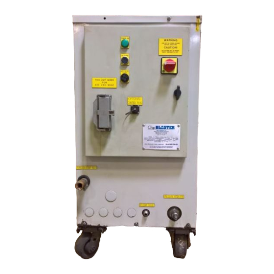
Page 61: Control Panel - Front
5753 + 5997 DIRTY FILTER ALARM HORN 2650 12 PIN P & C INTERFACE RECEPTACLE 5808 + 5809 ChipBLASTER DATA NAMEPLATE – STD ChipBLASTER DATA NAMEPLATE – CE OPTIONAL 9 PIN CONTROL INTERFACE 5146 RECEPTACLE + 5149 + 5150 DISCONNECT SWITCH... -
Page 62: Control Panel - Inside Enclosure
ChipBLASTER Inc 22.0. MECHANICAL ASSEMBLY (Cont.): 22.3. CONTROL PANEL – INSIDE ENCLOSURE ITEM No. DESCRIPTION PART No. TRANSFORMER 250VA (STD) 6076 TRANSFORMER 250VA (CE) 5911 ES RELAY 5706-CSA CONTROL RELAY CR1 & CR3 (120VAC) 5909 CONTROL RELAY CR1 & CR3 (24VDC) -
Page 63: Sub Plate Elevation - Left Side
ChipBLASTER Inc 22.0. MECHANICAL ASSEMBLY (Cont.): 22.4. SUB PLATE ELEVATION – LEFT SIDE ITEM No. DESCRIPTION PART No. FILTER HOUSING 3207 FILTER INLET FILTER OUTLET CHECK VALVE 9527 MAIN PUMP MOTOR 2007 TRANSFER PUMP 60Hz – WATER 2072A TRANSFER PUMP 60Hz – OIL 4251A TRANSFER PUMP 50Hz –... -
Page 64: Sub Plate Elevation - Right Side
ChipBLASTER Inc 22.0. MECHANICAL ASSEMBLY (Cont.): 22.5. SUB PLATE ELEVATION – RIGHT SIDE ITEM No. DESCRIPTION PART No. FILTER HOUSING 3207 HIGH PRESSURE GAUGE FEED HOSE TRANSFER PUMP 60Hz – WATER 2072A TRANSFER PUMP 60Hz – OIL 4251A TRANSFER PUMP 50Hz – WATER 2073A TRANSFER PUMP 50Hz –... -
Page 65: Manifold Block Assembly
ChipBLASTER Inc 22.0. MECHANICAL ASSEMBLY (Cont.): 22.6. MANIFOLD BLOCK ASSEMBLY (PLAN VIEW) ITEM No. DESCRIPTION PART No. RETURN (TRANSFER) PUMP 3510 RETURN (TRANSFER) PUMP INLET (HOSE BARB) 6022 MANIFOLD BLOCK 8308 HIGH PRESSURE COOLANT OUTLET RELIEF VALVE (REGULATOR) 4546 DUMP LINE HIGH PRESSURE COOLANT MANIFOLD INLET SOLENOID (DUMP) VALVE “C”... -
Page 66: Filter Assembly
ChipBLASTER Inc 22.0 MECHANICAL ASSEMBLY (Cont.): 22.7. FILTER ASSEMBLY: ITEM No. DESCRIPTION PART No. FILTER LID WITH HOLD DOWN ASSEMBLY 3208A FILTER CARTRIDGE (10 µM) 3015-10 O-RING SEAL (DISPLACED FROM GROOVE) O-RING GROOVE FILTER HOUSING 3207 FILTER INLET VENT VALVE (INCL W/ LID ASSY) 5543 22.7... -
Page 67: Ship Loose Items
HIGH PRESSURE HOSE ASSEMBLY 4801 FITTING, ½ JIS MALE x ½” BSPT MALE STRAIGHT 4214 CASTERS - SWIVELING 9070 FITTING, #8 JIC (37°) FEMALE SWIVEL x ½” NPT 4004 STRAIGHT (CONNECT TO ChipBLASTER) VALVE, CHECK ½” NPT FEMALE IN-LINE HP 4171 4214 22.8... -
Page 68: Spare Parts
ChipBLASTER Inc 22.0. MECHANICAL ASSEMBLY (Cont.): 22.13. SPARE PARTS: REFER TO DATA NAMEPLATE ON ENCLOSURE FOR CORRECT MODEL OF YOUR UNIT SPARE PARTS ITEM DESCRIPTION PART No. KIT PART KIT PART KIT PART 36807 36867 36837 QT'Y. / KIT QT'Y. / KIT QT'Y. -
Page 69: Footprint Drawing
ChipBLASTER Inc 23.0. FOOTPRINT DRAWING: 32.57 [827.4] 36.00 [914.4] 19.69 [500.0] 76.53 [1943.9] 42.43 [1077.6] 12.00 [304.8] 31.69 [804.8] 14.96 [379.9] 41.87 [1063.5] 23.0... -
Page 70: Warranty
4160 hours of operation from the date of original installation, subject to the conditions set forth below. During this warranty period, ChipBLASTER will repair or replace, at its sole option, defective products or parts without charge to the purchaser. - Page 71 This warranty specifically excludes reimbursement or liability for “downtime,” loss of income and/or consequential damages. In no event will ChipBLASTER’s liability to the purchaser resulting from any claim or loss arising out of a purchaser’s purchase of ChipBLASTER™ equipment or the operation thereof exceed the purchase price of the product manufactured or sold by ChipBLASTER.
-
Page 72: Warranty (Limited) - Used Equipment
90 days or 1040 hours from the date of installation, subject to the conditions set forth below. During this warranty period, ChipBLASTER will repair or replace, at its sole option, defective products or parts without charge to the purchaser. - Page 73 This warranty specifically excludes reimbursement or liability for “downtime,” loss of income and/or consequential damages. In no event will ChipBLASTER’s liability to the purchaser resulting from any claim or loss arising out of a purchaser’s purchase of ChipBLASTER™ equipment or the operation thereof exceed the purchase price of the product manufactured or sold by ChipBLASTER.
-
Page 74: Warranty (Limited) - Retrofits
During this warranty period, ChipBLASTER will repair or replace, at its sole option, defective products or parts without charge to the purchaser. ChipBLASTER, Inc. further warrants that its ChipBLASTER™ high-pressure retrofit systems will not adversely affect or damage the cutting equipment on which ChipBLASTER installs such systems. - Page 75 ChipBLASTER™ retrofits covered by this limited warranty, and are in lieu of any or all other remedies, whether based on statements or promises which are oral, written, express or implied, and whether in contract, tort, equity or otherwise.
-
Page 76: Warranty Claim Form
ChipBLASTER Inc 24.0. WARRANTY (Cont.): 24.4.WARRANTY CLAIM FORM WARRANTY CLAIM FORM Unit Serial # ___________________ Unit Description _________________________________ Purchased From ________________________________ Invoice # ___________________ Invoice Date ____________________ Installation Date ______________________ Nature of Problem (including date of occurrence) ________________________________________________________________________ ________________________________________________________________________ ________________________________________________________________________ ____________________________ 24.4... -
Page 77: Warranty Registration Card
ChipBLASTER Inc 24.0. WARRANTY (Cont.): 24.5. WARRANTY REGISTRATION CARD: ---------------------------------------------------------------------------------------------------------------- Detach this part of the sheet and mail to ChipBLASTER to activate your warranty. This form MUST be filled out completely to be a valid warranty registration. WARRANTY REGISTRATION CARD... -
Page 78: Warranty Validation Card
______________________ according machine model to ChipBlaster procedures (Note: ChipBlaster Standard Warranty will commence with the above signed date if all conditions of the procedures are met). SEND TO: ChipBLASTER (Office Use Only) -
Page 79: Optional Equipment
ChipBLASTER Inc 27.0. OPTIONAL EQUIPMENT: 27.1. MACHINE SUMP STANDPIPE ASSEMBLY (P/N 30011): Ø7.1 (180MM) 1.0 (25MM) RECOMMENDED PLACEMENT Ø6.3 (160MM) B.C. (4) Ø0.28 (7MM) HOLES EQ SP 27.1... -
Page 80: Supplement Data
ChipBLASTER Inc 28.0. SUPPLEMENT DATA: 28.1. Orifice Reference Chart for 1000 PSI Orifice Dia. Outlet Area Velocity (Ft./Sec.) Volume Horsepower Machine maximum (Sq. Inches) (GPM) Required outputs 0.010 0.0001 1000 0.015 0.0002 1000 0.020 0.0003 1000 0.025 0.0005 1000 0.030 0.0007...
Need help?
Do you have a question about the STANDARD UNIT D30-80-1 and is the answer not in the manual?
Questions and answers
Need part list for adjustable pump mount
Based on the provided context, the part list related to the adjustable pump mount (referred to as the HP Pump Mounting) for the ChipBLASTER STANDARD UNIT D30-80-1 includes:
- HP Pump Mounting Rail (Part No. 8286)
- HP Pump Slide Base (Part No. 2618)
- Pump Pulley (56T) (Part No. 2544)
- Timing (Drive) Belt (no part number provided)
This assembly is mentioned under the Mechanical Assembly section.
This answer is automatically generated