Table of Contents
Advertisement
DARE!!
DARE!! Products B.V.
CoC number: 30138672
VAT number: NL8056.13.390.B01
Eori number: NL805613390
Rabobank Utrechtse Waarden e.o.
IBAN: NL31RABO0158313585 ● SWIFT code RABONL2U
DARE!! Instruments
EMC & RF Measurement equipment
Vijzelmolenlaan 3
3447 GX, Woerden
The Netherlands
RadiSense
Product Manual
Electric Field Sensors
With RadiSupply plug-in card for the RadiCentre
Sensor Model:
RSS2010B
RSS2010H
RSS2010I
RSS2010S
Card Model:
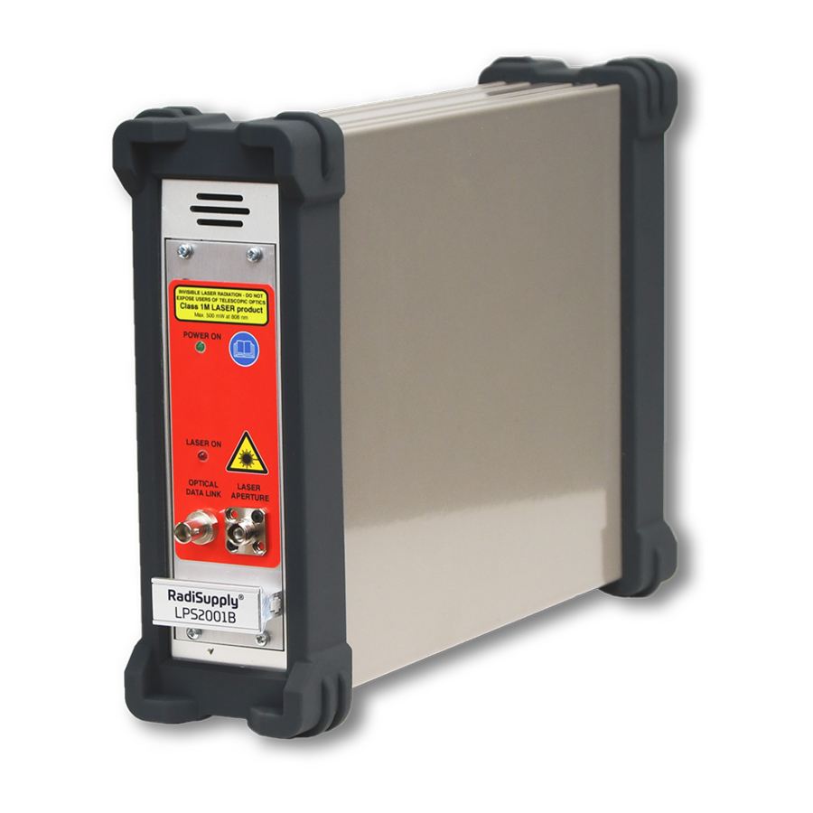
LPS2001B
Tel. +31 348 416 592
www.dare.eu
instruments@dare.eu
Advertisement
Table of Contents

Related Manuals for Dare RadiSense Series

Summary of Contents for Dare RadiSense Series
- Page 1 DARE!! Instruments DARE!! EMC & RF Measurement equipment Vijzelmolenlaan 3 Tel. +31 348 416 592 3447 GX, Woerden www.dare.eu The Netherlands instruments@dare.eu RadiSense Product Manual Electric Field Sensors With RadiSupply plug-in card for the RadiCentre Sensor Model: Card Model: RSS2010B RSS2010H LPS2001B RSS2010I...
- Page 2 RadiSense Product Manual This service and operating manual pertains to the RadiSupply plug-in card and the RadiSense electric field sensors. Card model: LPS2001B Sensor models: RSS2010B, RSS2010H, RSS2010I, RSS2010S Made by DARE!! Instruments. The RadiSense electric field sensors are used in combination with the RadiCentre modular EMC test systems.
-
Page 3: Table Of Contents
Table of Content WARNINGS & PRECAUTIONS ....................4 Introduction ....................... 6 Product Introduction ....................6 Related Products ....................... 6 The RadiSense ......................7 Product Characteristics .................... 7 RadiSense models ..................... 8 Fibre Optic Cables ..................... 9 RadiSupply Plug-In Card, Rear Panel ............... 9 LASER Safety Measures .................. -
Page 4: Warnings & Precautions
WARNINGS & PRECAUTIONS Read the contents of the product manual (including the manual for the RadiCentre system) and become familiar with the safety markings, instructions, operation and handling of the system. Only qualified service personnel is allowed to carry out adjustments, maintenance or repairs on the equipment. - Page 5 WARNINGS & PRECAUTIONS The RadiSense system is a closed loop fibre system and therefore classified as a Class 1M laser system according to EN60825-1:2014 and EN60825-2:2005. In order to provide laser safety in case of a fibre failure or accidental disconnection of the fibres, the RadiSense system is provided with an Automatic Laser Shutdown (ALS) as described in the EN60825-2:2005.
-
Page 6: Introduction
1. Introduction 1.1 Product Introduction The RadiSense 10 E-field sensor is the most accurate ultra-wideband sensor designed for electric field strength measurements. The sensor is small and fully optically isolated to minimize field perturbation. Applications for the E-field sensor are: Radiated immunity field monitoring ... -
Page 7: The Radisense
2. The RadiSense 2.1 Product Characteristics LASER Powered - The sensor is LASER powered without the need for batteries. This allows 24-7 continuous testing at maximum performance without the need to change or recharge batteries. Superb Measurement Accuracy – To perform accurate field measurements, the E-field sensor dimensions must be as small as possible compared to the wavelength of the measured signal. -
Page 8: Radisense Models
2.2 RadiSense models The RadiSense 10 sensor is available in four models: RSS2010B 9 kHz to 10 GHz, high speed / 1000 measurements/second RSS2010H 20 MHz to 10 GHz, high speed / 1000 measurements/second RSS2010I 9 kHz to 10 GHz, best isotropy / 100 measurements/second RSS2010S 20 MHz to 10 GHz, best isotropy / 100 measurements/second The RadiSense sensor can be delivered as single item or as SET. -
Page 9: Fibre Optic Cables
2.3 Fibre Optic Cables Use an extension fibre to connect the sensors to the plug-in card mounted in the RadiCentre. This extension fibre is a robust duplex fibre cable and uses dissimilar connectors to avoid misconnections. The fibre optic cable with FC connectors feeds LASER light to the field sensor. The fibre optic cable with ST connectors is used for bi-directional data communication between the field sensor and the plug-in card. -
Page 10: Laser Safety Measures
2.5 LASER Safety Measures The RadiSense uses a high-power LASER to supply energy to a remote measuring device. The wavelength of this LASER is approximately 808nm. This infrared laser is invisible to the human eye. During normal operation, exposure to LASER radiation is not possible because the RadiSense uses a fibre-coupled closed loop system with Automatic Laser Shutdown (ALS). - Page 11 RadiCentre 2-slot and 7-slot specific: A ‘LASER Code’ is required to activate the RadiCentre 2-slot and 7-slot systems. This LASER code enables the power supply to all installed (LASER) modules. (Please refer to Chapter 3.2 for the default laser code). ...
-
Page 12: Fibre Handling And Maintenance
2.6 Fibre Handling and Maintenance The fibre optic cables in the RadiSense are a crucial part of the system. Improper handling and poor maintenance can cause deterioration or permanent damage. Please read the following handling and maintenance guidelines to ensure both your safety and the quality of the product. 2.6.1 Handling guidelines Always place the plastic end-caps on the fibre connectors when they are not in use. - Page 13 2.6.3 Fibre conditions Use the examples and instructions in the following figure as a guideline for further fibre maintenance. If you have doubts about the condition of the fibre optic cables, please contact your local reseller or DARE!! Instruments for assistance and/or advise. Copyright ©...
-
Page 14: Probe Stand
2.7 Probe stand The RadiSense 10 is supplied with a PST2000A probe stand consisting of the following parts: Base Feet (3 pcs) Pole (3 pcs) Angle mount The probe stand parts can be easily assembled together. The 3 feet can be screwed into the side of the base. - Page 15 The use of the mounting angle is optional. For isotropic measurements of an electrical field of which the polarization is unknown (for example in reverb chamber / mode-stir chambers) the mounting angle is not needed, see left picture. For accurate measurements of electrical field with a known polarization, the mounting angle can be used to position one axis of the RadiSense parallel to the field.
-
Page 16: Installation
3. Installation 3.1 Hardware Configuration The hardware configuration is carried out in the following 7 steps: 1. Choose the slot of the RadiCentre system in which you want to install the plug-in card. 2. Remove the blind panel from this slot by removing the four screws of the panel (two on top and two at the bottom). -
Page 17: Laser Code
5. Connect the plug-in card to the desired device(s). Place the RadiSense E-field sensor where the field strength is to be measured. Clean the ends of the fibres and connect the cables to both the sensor and the plug-in card. Make sure the latching pin (notch) of the FC and ST connector fits correctly in the slot of the chassis connector (in line coupling). - Page 18 The default LASER code is: 3447 This code can be changed by the customer in the main configuration screen (see below)). To change the laser code, the user will be asked to enter the current code once and the new code twice (for confirmation).
-
Page 19: Software Configuration
3.3 Software Configuration To control the RadiSense from a computer, one can use either custom made software or the RadiMation EMC software package from DARE!! Instruments, which can be downloaded from the DARE!! Instruments website. If the RadiSense is operated manually, this chapter can be skipped. If RadiMation software is used;... - Page 20 4. The new driver can be configured by double clicking the driver and press the ‘Advanced’ button. Another window opens, where you can select the communication tab and choose the control interface. In this example, we use USB. 5. To enable the USB communication, make sure the RadiSense probe is connected to the PC USB port and press the ‘Detect’...
- Page 21 7. For controlling the RadiSense probe from a RadiCentre 2-slot or 7-slot system (CTR1004B or CTR1009B) select under the tab “RadiCentre” the “RadiCentre Multi- slot’ and define the corresponding slot number in which the RadiSense probe is installed. In this example the probe is installed in slot number 8.
- Page 22 10. Under the “RadiSense’ tab the RadiSense 10 can be configured to provide isotropic field strength measurements of all three axes or if individual (single) axis measurements are being performed. Furthermore, the filter settings can be configured. 11. Upon completion of the settings click on ‘OK’. 12.
-
Page 23: Using The Radisense
4. Using the RadiSense 4.1 Manual Control Once the RadiCentre is switched on, the RadiSense can be activated from the ‘main’ screen on the RadiCentre touchscreen. 4.1.1 Starting the LASER powered sensor The LASER of the RadiSense 10 field sensor can be started from the ‘main’ window of the RadiCentre. - Page 24 As soon as the probe is zeroed, the ‘STATUS’ box will display the measured field strength of the probe (see below). The E-field sensor is now powered on and will return optical data to the RadiCentre system. As long as the probe returns optical data, the LASER will continue to power the sensor. If the loop is interrupted, the LASER will switch off immediately.
- Page 25 The ‘Instrument’-screen will display the isotropic field strength in a large font, together with the field strength data of each separate axis. In addition; probe information and LASER information are also displayed in the ‘Instrument’-screen The calculation of the isotropic field strength, is done according to the following formula: + Ey + Ez With the ‘Frequency’...
-
Page 26: Radisense 10 User Correction Calibration Data
5. RadiSense 10 User correction calibration data The RadiSense 10 probe has the feature to store external (IS017025 accredited) calibration data as “user correction factors” inside the probe. This means that the correction data will be applied to the measured field in run time. Due to this, there is no longer a need to apply correction factors inside a measuring application, like RadiMation. -
Page 27: Manually Create And Upload Of User Correction File
5.1 Manually create and upload of user correction file In case the RadiSense 10 field sensor has been calibrated at DARE!! Calibrations, the frequency response correction factors are provided in Microsoft® Excel file format. Use the following steps to create a correction file text string in the right format: 5.1.1 Modify Excel file In the Excel file with the calibration correction factors place the correction data with the... - Page 28 As an example, this will result into the following Excel table: 5.1.3 Create the text string per frequency This can be done using the following formula: “=CONCAT(AD14;",";AE14;",";AF14;",";AG14;";")”. “AD14” must be the cell where the frequency is stored “AE14” must be the cell where the CF of the X-axis is stored “AF14”...
- Page 29 5.1.4 Combine the text strings of the frequencies to one text string This can be done by applying the following formula: “=CONCAT(AI14:AI106)” “AI14” must be the cell which is the top of the list with text strings per frequency. “AI106” must be the last cell of the list with text strings per frequency. The result will be one cell with a long string.
- Page 30 Start the program “Putty” - Select the USB com port where the CTR1001S is connected to; - Set the baudrate to 115200 baud; - Select connection type: Serial Then click on “Open” to open the serial port to the RadiSense 10 probe. Type “*IDN?”...
- Page 31 Send the “CALSTORE” command. The response should be: “OK”. Send the correction table, which is the text string we have created in Excel Copy the text sting in Excel. With a right mouse click in “Putty” the text string can be pasted. After pasting, press ENTER.
- Page 32 Wait for the “OK” response. Verify that the table is programmed correctly into the RadiSense 10 probe by dumping the table. Send the “CALDUMP” command. The response should be the table which is programmed by the “CALSTORE” command. Turn the correction factors ON. This can be done by using the “CAL ON” command. The response should be: “OK”...
-
Page 33: Create And Upload User Correction With Radimation
5.2 Create and upload user correction with RadiMation In case the RadiSense 10 field sensor has been calibrated at DARE!! Calibrations, the frequency response correction factors are provided in Microsoft® Excel file format. Use the following steps to create a correction file in RadiMation: 5.2.1 Create a User correction file To create a new correction file, first start RadiMation. - Page 34 By individually selecting the X, Y and Z axis correction and pressing the ‘Add’ button, the requested column type shall be added to the list of columns in the correction file. When you are done adding the required columns, press ‘close’. 5.2.2 Add calibration data into the correction file After adding the required column types the User correction data can be filled into the correction...
- Page 35 5.2.3 Add calibration data into the correction file When opening the device driver settings for the RadiSense 10 probe in RadiMation the following screen shall be presented. Click on the Advanced button to open the advanced configuration dialog for the RadiSense 10 device driver.
- Page 36 5.2.4 Store calibration data into the correction file Select ‘Browse’ to open a file picker and browse to the location of the RadiMation correction file and Select the file. After selecting the file, the file location shall be displayed in the text field. When the file has been added, press the ‘Program calibration table’...
-
Page 37: Error Codes - User Correction Table
5.3 Error codes - user correction table During uploading of the correction file the following error messages might be returned. Error message Cause Incorrect column amount A wrong number of columns is used in the correction file. Incorrect precision A value in the correction file has a too high precision. Correction factor out of range A value in the correction file is greater than 3.00. -
Page 38: Radisense Remote Control And Error Codes
6. RadiSense remote control and error codes 6.1 General The RadiSense can be controlled remotely through the interfaces of the RadiCentre. The exact communication protocol, including the specific commands for the RadiSense probe and a listing of all error codes can be found in the RadiCentre manual. Please note that every command must be terminated with a carriage return (CR). -
Page 39: Radisense Specifications
7. RadiSense Specifications RadiSense 10 Model RSS2010B Electric Field Field measurement 1 to 750 V/m range Max input level before 1000 V/m damage Frequency range 9 kHz to 10 GHz (usable to 12 GHz) Accuracy Frequency response 9 kHz to 10 MHz - 3 dB to + 1 dB 10 MHz to 1 GHz - 1 dB to + 1,5 dB... - Page 40 RadiSense 10 Model RSS2010H Electric Field Field measurement 1 to 750 V/m range Max input level before 1000 V/m damage Frequency range 20 MHz to 10 GHz (usable to 12 GHz) Accuracy Frequency response 20 MHz to 1 GHz - 1 dB to + 1,5 dB 1 GHz to 10 GHz - 3 dB to + 3,5 dB <...
- Page 41 RadiSense 10 Model RSS2010I Electric Field Field measurement 1 to 750 V/m range Max input level before 1000 V/m damage Frequency range 9 kHz to 10 GHz (usable to 12 GHz) Accuracy Frequency response 9 kHz to 10 GHz 1 dB <...
- Page 42 RadiSense 10 Model RSS2010S Electric Field Field measurement 1 to 750 V/m range Max input level before 1000 V/m damage Frequency range 20 MHz to 10 GHz (usable to 12 GHz) Accuracy Frequency response 20 MHz to 10 GHz 1 dB <...
- Page 43 RadiSense Specifications, part 2 Model RadiSense 10 Optical LASER power Max. 0,5 Watt output at aperture Wavelength 808 nm LASER connector FC/PC Data connector ST/PC Fibres 200/230 µm HCS, duplex 1,5 m fixed to sensor, 10 m extension with couplings Standard Fibre length Other lengths available on request Safety...
-
Page 44: Warranty Conditions
7.1 WARRANTY CONDITIONS DARE!! Instruments offers a standard warranty term of three years on their products, starting from the shipping date. This warranty is applicable to all EMC test & measurement products, such as: RadiCentre modular / multifunctional EMC test systems •... -
Page 45: European Declaration Of Conformity
7.2 EUROPEAN DECLARATION OF CONFORMITY We, DARE!! Instruments declare under our sole responsibility that the product; RadiSense Plug-in card model LPS2001B, with Electric field sensor models RSS2010B, RSS2010H, RSS2010I, RSS2010S to which this declaration relates, is in accordance with the following Directives: EMC-Directive 2014/30/EU Low Voltage Directive 2015/35/EU RoHS-Directive: 2011/65/EG...
Need help?
Do you have a question about the RadiSense Series and is the answer not in the manual?
Questions and answers