Advertisement
Quick Links
Operation Manual
Thank you very much for purchasing FY series printer
In order to use FY series printer correctly and safely and understand this product's capability,
please read this manual carefully.
This manual includes equipment structure, description, technical parameters, operation manual,
safety information, application of software, etc.
This manual is subject to change without notice.
Contents herein contained are believed to be correct, however, please contact us if you find any
error or something not clear enough.
Copyright 2010 Fei Yeung Union. All rights reserved.
FY‐3266J
1
th
14
Oct. 2010
Version : 1.0
Advertisement

Summary of Contents for Fei Yeung Union FY Series
- Page 1 Thank you very much for purchasing FY series printer FY‐3266J In order to use FY series printer correctly and safely and understand this product’s capability, please read this manual carefully. This manual includes equipment structure, description, technical parameters, operation manual, safety information, application of software, etc.
-
Page 2: Table Of Contents
Table of Contents Chapter 1: Safety Precaution…………………………………….… 3 Chapter 2: Preparation and Procedures for Assembling………5 Chapter 3: Machine Structure and Accessories…………………9 Chapter 4: Basic Operation………………………………….,,,…...14 Chapter 5: Maintenance Guide……………………………………..37 Chapter 6: Troubleshoot …………..……………………………..…..42 Chapter 7: Technical Specification………………………………..44 ... -
Page 3: Chapter 1: Safety Precaution
Chapter 1 Safety Precaution 1.1 Important Safety Measures Please read the following instructions before using the printer. Follow cautions and instructions which are labeled on the printer. - Page 4 Chapter 1 Safety Precaution 1.2 Handling Printer Caution Do NOT move the carriage when the power is on. Always use the power switch to turn on or off the printer.
-
Page 5: Chapter 2: Preparation And Procedures For Assembling
Chapter 2 Preparation and Procedures for Assembling 2.1 Environment requirement ℃ Keep the room temperature between 20—30 , and the humidity between 40 —60%. Air conditioner and humidifier may require. Keep a distance from strong radiation field. The floor must be level. - Page 6 Chapter 2 Preparation and Procedures for Assembling 2.2 Electrical requirement The printer only supports AC 220V. A transformer is needed if the area is using AC110V. The printer must be well grounded ( the grounded voltage should be less than 0.3V, and the grounded resistance should be less than 4 Ω...
- Page 7 Chapter 2 Preparation and Procedures for Assembling 2.4 Procedures of Assembling Move the packing box to the working site and avoid strong shaking. Disassemble the wooden packing box from top to bottom. Check whether the parts are complete or not according to the packing list. Lift the printer out by a forklift, and move it to the installation site.
- Page 8 Chapter 2 Preparation and Procedures for Assembling Figure 2-1 Attention A: When assemble the aluminous cap, you should screw on the aluminous cap perpendicularly avoiding to damage the screw thread of the damper. Attention B: When assemble new printhead, it’s unnecessary that you flush the printhead additionally with solvent.
-
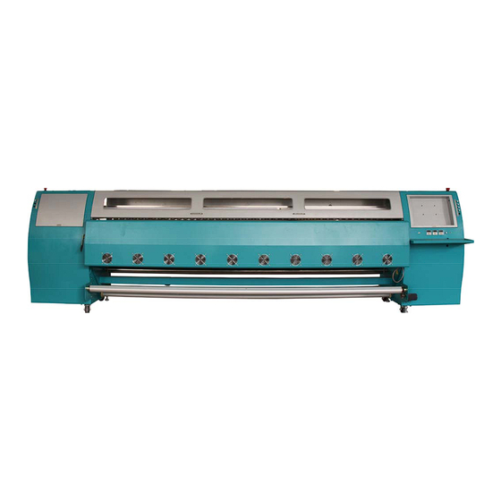
Page 9: Chapter 3: Machine Structure And Accessories
Chapter 3 Machine Structure and Accessories 3.1 Machine Structure: (3) (2) (1) (4) (1)Left Emergency Stop (2)Cover (3)Girder (4)Right Emergency Stop (5)Left Machine Box (6)Right Machine Box (7)LCD Monitor Installing Position (5) (6) (7) (8)Cooling Fan (9)Take-up Bar (10)Balancing Bar... - Page 10 Chapter 3 Machine Structure and Accessories (18) (14)Electronic Board (15)Single Feeding Bar (16)Double Feeding Bar (17)Media Pulling Bar (18)Ventilation Outlet ...
- Page 11 Chapter 3 Machine Structure and Accessories (8) (9) (8) Printhead voltage (9) Media suction (10) Take-up main switch (10) (11) Take-up auto/manual switch (11) (12) Direction switch (12) Take‐up Control: Power OFF ON Auto/Manual Auto Manual Direction Stop ...
- Page 12 Chapter 3 Machine Structure and Accessories (19) (19) Printhead light (20) (20) & (21) Solvent cleaning (21) (22) Feeding system switch (23) Auto/manual switch (24) Direction switch Feeding Control: (22) Power OFF ON (23) Auto/Manual Manual Auto ...
- Page 13 Chapter 3 Machine Structure and Accessories 3.3 Ink Supply System (8) ( 9) (10) (12) (13) (14) (1)K ink pump (2)C ink pump (3)M ink pump (4)Y ink pump (5)Lc ink pump ...
- Page 14 Chapter 4 Basic Operation 4.1 Feeding Instruction 1) Load the material to the media support bar Platen ...
- Page 15 Chapter 4 Basic Operation 3) Press the motor drive pinch roller button to press the pinch roller. Pinch roller pressed!...
- Page 16 Chapter 4 Basic Operation 5) Press the pressure bar to the pulling bar Pressure bar Pulling bar ...
- Page 17 Chapter 4 Basic Operation 4.2 Characteristics SPT 1020_35pl printheads x 6; Resolution: X direction 720\360\240 DPI; Y direction 1080\720\360 DPI;...
- Page 18 Chapter 4 Basic Operation 4.3 Software Installation This software consist of printer driver, printing adjustment and picture printing functions. Running this software requires a certain hardware and software condition.
- Page 19 Chapter 4 Basic Operation 3) Click “Next”, installation path is available to choose. Choose the directory to install.
- Page 20 Chapter 4 Basic Operation 4.4 Software Interface 1) Control panel introduction: ,double-click the icon to open the software. Let us Find the following shortcut icon take a look at the main interface first.
-
Page 21: Chapter 4: Basic Operation
Chapter 4 Basic Operation Server IP address: Display Local IP address,the IP address of the printer is 127.0.0.1 when online printing is taken place. - Page 22 Chapter 4 Basic Operation Then,click “OK” to finish testing. 1. 3 Y motor gear ratio setting: "Test" --> "Y motor Test" First of all, we marked a sign (1) on a certain place of the printer platform, then click “Test Begin”, the media will be fed a bit, then mark a sign (2) on the same position.
- Page 23 Chapter 4 Basic Operation Click "OK" to quit the software. Restart the software and redo the "Y motor Param Setting" until the actual feeding distance is 10mm.
- Page 24 Chapter 4 Basic Operation Noted:Speed calculation method:(Print head frequence/Print mode)*25.4 = carriage speed 240 mode:normal=(6460Hz/240dpi)*25.4mm=684mm/s, high=(8000Hz/240dpi)*25.4mm=847mm/s;...
- Page 25 Chapter 4 Basic Operation 2.2 Printhead order printhead board: ...
- Page 26 Chapter 4 Basic Operation 2.3 HVert: Printhead angle alignment. Observe the physical alignment of printheads. )...
- Page 27 Chapter 4 Basic Operation Situation 2:The second line is at the left of the first line: ...
- Page 28 Chapter 4 Basic Operation B) Check whether the horizontal lines are aligned (When the vertical alignment is done, the horizontal should be aligned as well.
- Page 29 Chapter 4 Basic Operation Default Setting of Uniclr: ;C:1‐2= ‐9 ;M:1‐2= ‐9 ;Y:1‐2= ‐9 ;Lc:1‐2=‐9 ;Lm:1‐2=‐9 K:1‐2= ‐9 Please click the “Save Parameters” after inputing values, then print the adjusting picture of the same color again.
- Page 30 Chapter 4 Basic Operation Enter “Setting\Option”, showed as the below picture: Based parameter Choose “Head Adjustment” ...
- Page 31 Chapter 4 Basic Operation 2.6 Bidir (Bi-direction adjustment) “Bidir” shortcut is shown in the following: Bidirectional Adjustment will be done while the printing speed changed.
- Page 32 Chapter 4 Basic Operation 2.7 Step Adjustment The location for button of “Step” on the menu of shortcut is showed as the below picture: Print the below adjusting picture by clicking the button of “Step” Add ‐4 Make the two lines at “0” as the standard. If the two lines at “0” are not in complete superposition, ...
- Page 33 Chapter 4 Basic Operation 4.6 Other Functions 1. Network Printing Setup (enter “Setting\Setting”) Setup of Network Printing Port Setup of Buffer ...
- Page 34 Chapter 4 Basic Operation Input Adjustment of Printhead Printhead Voltage Offset Default Voltage Actual Printhead Voltage Actual Printhead Temperature Options of Printhead Group ...
- Page 35 Chapter 4 Basic Operation 3.1 Printing Mode There are two options for unidirection and bidirection. 3.2 X Direction Mode This is an option which is used for adjusting printheads alignment.
- Page 36 Chapter 4 Basic Operation 3.8 Feather Setting To blur the pass line,feather pass edge. 1) Option: Enable/Disable the feather function. 2) Nozzle: Setup for nozzle number of feather.
- Page 37 Chapter 5 Maintenance Guide 5.1 Normal Cleaning: Positive Pressure Cleaning Press the cleaning button, and then use sponge stick or soft fabric to wipe the surface ...
- Page 38 Chapter 5 Maintenance Guide Daily maintenance 1) Please print the “Nozzles Checking” to make sure all the nozzles are firing fine before switching off the printer.
- Page 39 Chapter 5 Maintenance Guide 5) Place the cap in the waste tank, and move the carriage back to home. (Figure 5-5) Figure5-5 ...
- Page 40 Chapter 5 Maintenance Guide 5.7 Cleaning procedures for nozzle clogging 1) Disconnect the tube connector for the tube from the Subtank to the printhead.
-
Page 41: Chapter 5: Maintenance Guide
Chapter 5 Maintenance Guide Step 1 Step 2 Step 3 Ink inlet PE film Close the cap.Ensure the Cut the PE film into 30cm x30cm Place ... -
Page 42: Chapter 6: Troubleshoot
Chapter 6 Troubleshoot After turning on the printer, the 12V, 24V, and 35V LED on the connecting board are lit on. - Page 43 Chapter 6 Troubleshoot 6) Flash jetting is normal when turning on. After printing for awhile, does not flash jetting, but printing normally:...
-
Page 44: Chapter 7: Technical Specification
Chapter 7 Technical Specification Specification FY-3266J Model Printhead SPT1020-35PL Number of printhead 6Heads Max. printing width 3200mm Max. media width 3300mm Printing Mode Output(m Draft 2pass...