Table of Contents
Advertisement
Advertisement
Table of Contents

Subscribe to Our Youtube Channel
Related Manuals for INCOE MICROCOM

Summary of Contents for INCOE MICROCOM
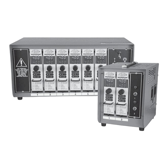
- Page 1 MICROCOM ® I Temperature Controller Instruction Manual...
-
Page 2: Table Of Contents
MICROCOM TEMPERATURE CONTROLLER ® INSTRUCTION MANUAL TABLE OF CONTENTS 1 INTRODUCTION Main Function Pg. 2 Controller Specifications Pg. 2 Technical Features Pg. 2 1.3.1 Temperature Measurement Pg. 2 1.3.2 Temperature Control Pg. 2 1.3.3 Power Output Pg. 3 1.3.4 Other Functions Pg. -
Page 3: Introduction
INTRODUCTION 1.1 MAIN FUNCTION: • Broken Thermocouple detection automatically switches to manual mode by applying the last stored percentage of power to the heater The MICROCOM ® temperature controller is (adjustable through software). designed to control hot runner systems. 1.2 CONTROLLER SPECIFICATIONS: •... -
Page 4: Power Output
• Double protection of the load via fuse (Ref : FA15 or ABC-15). 1.3.4 OTHER FUNCTIONS : • Protection against over voltages (overvoltage • Voltage correction (INCOE Patent 6,107,610): ® switch calibrated to 275V). the system uses a second closed loop control, •... -
Page 5: Operation
MICROCOM TEMPERATURE CONTROLLER ® INSTRUCTION MANUAL OPERATION 2.1 REQUIREMENTS FOR INSTALLING AND USING: • The controller type (World). The control module is designed to operate in a dry industrial environment. Operating Temperature range : from 14°F to +158°... -
Page 6: Controller Operating Mode
MICROCOM TEMPERATURE CONTROLLER ® INSTRUCTION MANUAL OPERATION 2.5 CONTROLLER OPERATING MODE: 2.5.2 STANDBY DISPLAY: 2.5.1 DESCRIPTION: In normal operating mode, the upper digits display the temperature whereas the lower ones display This controller consists of the following: the setpoint. A “CLICK & ROTATE” switch for data entry If an alarm or a fault, occurs it will be displayed on and viewing. -
Page 7: Click & Rotate" Switch Locking Procedure
MICROCOM TEMPERATURE CONTROLLER ® INSTRUCTION MANUAL OPERATION 2.5.4 “CLICK & ROTATE” SWITCH Heating element load resistance fault: LOCKING PROCEDURE: • This fault displays alternately with temperature. Automatic detection If the LOC parameter is set to ON (in the of load nominal power variation. -
Page 8: Main Menu
MICROCOM TEMPERATURE CONTROLLER ® INSTRUCTION MANUAL OPERATION CFG 1 Menu (Double click to Exit). Display of the percentage of power applied to load (Heater) : High Alarm user select In manual mode, the value in the display corresponds to the manual output setting. -
Page 9: Configuration Menu
MICROCOM TEMPERATURE CONTROLLER ® INSTRUCTION MANUAL OPERATION Minimum setpoint : 2.6.1 CONFIGURATION 1 MENU: Adjustable parameter to limit the setpoint to a minimum value (by default 0°C). The configuration 1 menu is as follows : Navigation via “Click & Rotate” switch:... - Page 10 MICROCOM TEMPERATURE CONTROLLER ® INSTRUCTION MANUAL OPERATION When temperature reaches setpoint, the ramp is Thermocouple type: complete. Its duration depends on the variation Parameter allows the selection of the type of between setpoint and temperature and on the thermocouple used. Either a type J, or type K increase per minute selected.
- Page 11 MICROCOM TEMPERATURE CONTROLLER ® INSTRUCTION MANUAL OPERATION If this parameter is set at “OFF”, the Navigation via “Click & Rotate” switch: controller displays an “otc” alarm and does not apply any voltage to the heater when a If “Increase”display thermocouple failure occurs.
-
Page 12: Trouble Shooting
Heater overheating. The standby screen displays TRIAC disconnected and Send the controller to the message “Str” alternately stops heating. INCOE for repair. with temperature. Tempera- ture increasesing no control even in Manual Mode. Fuses blowing 16A The heater The standby screen displays Change the faulty fuse. -
Page 13: Wiring Schematics & Plug Diagrams
MICROCOM TEMPERATURE CONTROLLER ® INSTRUCTION MANUAL WIRING SCHEMATICS & PLUG DIAGRAMS 4.1 DIAGRAM LABEL 4.2 1 & 2 ZONE ENCLOSURES S15405DB PIN 13 PIN 14 HEATER HEATER PIN 15 PIN 16 - T/C + T/C www.incoe.com ©INCOE ® CORPORATION 3/2011... -
Page 14: Zone Enclosures Utilizing 1614-Bra
MICROCOM TEMPERATURE CONTROLLER ® INSTRUCTION MANUAL WIRING SCHEMATICS & PLUG DIAGRAMS 4.3 4 ZONE ENCLOSURES UTILIZING 1614-BRA 4 ZONE ENCLOSURES UTILIZING 1614-BRA ENCLOSURE ZONES + THERMOCOUPLE - THERMOCOUPLE NOT USED POWER OUT POWER OUT POWER IN POWER IN GROUND 10 11 12... -
Page 15: Zone/8 Zone Enclosures Utilizing 3214-Bra
MICROCOM TEMPERATURE CONTROLLER ® INSTRUCTION MANUAL WIRING SCHEMATICS & PLUG DIAGRAMS 4.4 6 ZONE/8 ZONE ENCLOSURES UTILIZING 3214-BRA 6 ZONE/8 ZONE ENCLOSURES UTILIZING 3214-BRA ENCLOSURE ZONES 1 + THERMOCOUPLE 1 2 - THERMOCOUPLE 2 3 NOT USED 4 POWER OUT... -
Page 16: Zone Enclosures Utilizing 4814-Bra
MICROCOM TEMPERATURE CONTROLLER ® INSTRUCTION MANUAL WIRING SCHEMATICS & PLUG DIAGRAMS 4.5 12 ZONE ENCLOSURES UTILIZING 4814-BRA 12 ZONE ENCLOSURES UTILIZING 4814-BRA ENCLOSURE ZONES + THERMOCOUPLE - THERMOCOUPLE NOT USED POWER OUT POWER OUT POWER IN POWER IN GROUND 10 11 12... -
Page 17: General Terms & Conditions Of Sale
MICROCOM TEMPERATURE CONTROLLER ® INSTRUCTION MANUAL WARRANTY 5.1 GENERAL TERMS & CONDITIONS OF SALE 5 Delay of Shipment or Performance Excused for Various Reasons 1 Applicable Law and Jurisdiction A. If shipment of any item or other performance by Seller is delayed at the request of or due... - Page 18 MICROCOM TEMPERATURE CONTROLLER ® INSTRUCTION MANUAL WARRANTY C. Seller‘s warranties shall apply only if the Goods: (i) have been installed, maintained, and under any duty to inspect the Goods for any defects or any improper use or modification used in conformity with instructions furnished by Seller from time to time, if any; (ii) have of the Goods nor to correct or advise the Buyer of any such condition, use or modification, been subjected to normal use for the purpose for which Goods were designed;...
-
Page 19: Global Service Contacts
® following Patents: USA 5,269,677; 5,660,369; Canada 2,062,903; Germany 4028660; 4324275; Japan 2,093,613; and other Sales & Support: foreign patents pending. T: + 852 2790-8840 F: + 852 2790-8411 © INCOE Corporation 4/2010 E: info.hk@incoe.cn www.incoe.com ©INCOE ® CORPORATION 4/2010... -
Page 20: Global Offices
MICROCOM TEMPERATURE CONTROLLER ® INSTRUCTION MANUAL GLOBAL OFFICES 6.2 GLOBAL OFFICES INCOE NORTH AMERICA ® INCOE CHINA | SHANGHAI ® INCOE Corporation ® INCOE Hotrunners (Shanghai) Co., Ltd. ® 1740 East Maple Road 399 Xuanzhong Road, Building 16 Troy, Michigan 48083... - Page 21 MICROCOM TEMPERATURE CONTROLLER ® INSTRUCTION MANUAL NOTES www.incoe.com ©INCOE ® CORPORATION 4/2010...
- Page 22 ©INCOE® CORPORATION 5/2009 rev. 3/11 reprinted 4/11...
Need help?
Do you have a question about the MICROCOM and is the answer not in the manual?
Questions and answers