Table of Contents
Advertisement
Quick Links
Advertisement
Table of Contents

Summary of Contents for Ratmon RAT-2
- Page 1 USER MANUAL...
-
Page 2: Table Of Contents
Description of the device ......................4 Connection of the device to the pipe ......................5 Configuration of the device before connecting to the pipe ............... 10 Configuration of the device to work with RATMON system ............... 11 RATMON system ..........................12 Front panel ............................13 Description of LEDs .......................... -
Page 3: Content Of The Box
The current version of the manual is available at www.ratmon.com INTENDED USE OF THE DEVICE RAT-2 is the detector of leaks and faults in pre-insulated pipe network Leak / Fault detection is done by measuring of 2 below parameters: Rc - measurement of alarm loop continuity. -
Page 4: Description Of The Device
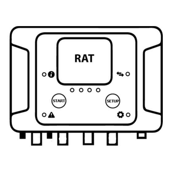
DESCRIPTION OF THE DEVICE 1. Button „Start” 11. Antenna socket 2. Button „Setup” 12. Connection channel 1 „CH1” 3. Status LED „ i ” 13. Connection channel 2 „CH2” 4. Alarm LED 14. Connection channel 3 „CH3” 5. Communication LED „Arrows” 15. -
Page 5: Connection Of The Device To The Pipe
CONNECTION OF DETECTOR TO THE PIPE WARNING! All connections of the detector to alarm wires and exchange of SIM card must be carried out with switched off power supply!! CONNECTION OF RAT-2 DETECTOR TO ALARM WIRES WITHOUT CONNECTION BOXES. - Page 6 CONNECTION OF RAT-2 DETECTOR TO ALARM WIRES USING BOX-1...
- Page 7 CONNECTION OF RAT-2 DETECTOR TO ALARM WIRES USING BOX-2...
- Page 8 CONNECTION OF RATCOMBO TO ALARM WIRES WITHOUT CONNECTION BOXES.
- Page 9 CONNECTION OF RATCOMBO TO ALARM WIRES USING BOX-3...
-
Page 10: Configuration Of The Device Before Connecting To The Pipe
To change the settings, use the RAT Manager 2 software, available at www.ratmon.com (see RAT Manager 2 manual, settings). If the device is equipped with a GSM module and is configured to work with the RATMON system, all parameters can be also changed by remote from RATMON system. Settings of operating parameters... -
Page 11: Configuration Of The Device To Work With Ratmon System
CONFIGURATION OF DEVICE TO WORK WITH RATMON SYSTEM 1. Download and install on your tablet / computer with Windows 7/10the current version of RATManager 2 (www.ratmon.com -> Download -> RATManager 2). 2. Connect the RAT device to the power supply. -
Page 12: Ratmon System
In order to view the results and manage the device, log in to the RATMON system at: www.app.ratmon.com The first step is to add the device to RATMON system and assign it to pipe loop. A detailed description is available in the "Help" of the RATMON system in Chapter 1 "First steps". -
Page 13: Front Panel
FRONT PANEL Colours of LEDs - dark blue - light blue - green - red - orange - purple - white LEDs and buttons on front panel Status Alarm Communication Functions channel 1 channel 2 channel 3 channel 4 „Setup” Button to select function „Start”... -
Page 14: Description Of Leds
3 x flashing - successful connection with server (RATMON) slow flashing - lack of SIM card or problem with SIM card fast flashing - problem with connection with server/RATMON. Next attempt to connect will be done by next measurement. constant flashing - problem GSM communication, device continues attempts to connect... -
Page 15: Led Operation After Starting Of The Device
LEDs CH1..CH4 warning - exceeding the warning threshold on channel CH X alarm - exceeding the alarm threshold on channel CH X resistance measurement on CH X TDR measurement on channel CH X flashing – firmware update in progress level of GSM signal strength LED OPERATION AFTER STARTING THE DEVICE 1. -
Page 16: Disposal
3. Manual checking of GSM signal strength In order to check current GSM signal strength, press once button „Setup” until LED starts flashing purple and next press button „Start”. The level of GSM signal strength will be presented on LEDs CH1 to CH4 in purple. 4.
Need help?
Do you have a question about the RAT-2 and is the answer not in the manual?
Questions and answers