
Summary of Contents for D.A.C.E SOLO
- Page 1 INSTALLATION & INSTALLATION & INSTALLATION & INSTALLATION & OWNERS MANUAL OWNERS MANUAL OWNERS MANUAL OWNERS MANUAL SOLO and SPRINT Incorporating the: DIGITAL BUSINESS CARD...
-
Page 2: Table Of Contents
SITE INFORMATION GATE MASS, START UP & RUNNING FORCE REMOVING THE LID MANUAL OVERRIDE PC BOARD LAYOUT ELECTRICAL WIRING (SOLO 500; CONDO) ELECTRICAL WIRING CONDO AC/DC ONLY ANCHORING THE OPERATOR SECURING THE OPERATOR TO THE FOUNDATION PLATE MOUNTING THE MAGNET MOUNTING THE RACK FILLING THE GEARBOX WITH OIL (CONDO &... -
Page 3: Introduction; Recommendations & Legal Requirements P3
D.A.C.E has taken all reasonable steps to ensure that the gate operator is safe to install and use. However it must be remembered that a gate is a heavy piece of moving equipment and may cause serious damage or injury if the gate strikes an object or person. -
Page 4: Recommended Tools P4
• Do not open, tamper or modify any of the electrical components of this equipment in any way. • Do not attempt to repair the equipment, this should only be done by a qualified D.A.C.E. tech- nician. • D.A.C.E will not be held liable for any accident / incident resulting in damage, injury or death ensuing from the installation of the automatic gate operator. -
Page 5: General Information P5
The gate will close on the next trigger that it receives or after the auto-close time has expired. It should be noted that D.A.C.E. recommends the use of DuraOptics safety beams on all installa- tions to minimise the chance of the gate closing while there is an object in its path. -
Page 6: General Site Layout P6
GENERAL INFORMATION cont. • End stop: a physical stopper preventing the gate from running off the end of the rail and causing injury or damage. • Intercom: equipment that allows communication between the gate and the house. • LCD Screen: indicates information regarding the operator status. •... -
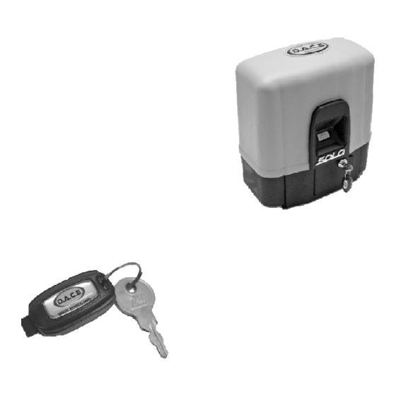
Page 7: Operator Layout P7
12V DC Electric Motor Manual override access door with lock Override access key Transformer Cable risers SOLO/SPRINT OPERATOR A. Conduit entry holes. B. 4 Holes for bolting the plate to the concrete plinth. C. Jacking bolts to secure the operator to the plate and for height adjustment. -
Page 8: Site Information P8
SITE INFORMATION The site should be evaluated before the installation begins. The following items should be checked. • The operator should be installed above flood level to avoid any water damage to the operator. • To avoid the operator from malfunctioning the rail should be level and above ground level. This will help to keep debris out of the path of the wheels. - Page 9 At no stage while moving the gate must the reading exceed the force shown in the table below. The D.A.C.E warranty will be void if the gate mass, start up force or running force exceeds the specifications as per the table below MAX.
-
Page 10: Removing The Lid P10
REMOVING THE LID SOLO/CONDO OPERATORS STEP 2 STEP 1 Pull out the pin (the pin will move about 5 mm). Open the access door The lid can now be removed PLACING THE OPERATOR IN MANUAL OVERRIDE Step 1: Unlock and open the access door (as in step 1 above). -
Page 11: Pc Board Layout P11
PC BOARD LAYOUT The PC Board is a sensitive piece of electronic equipment and should be handled with care. • Never connect or remove wires on a PC Board while there is power on the board as this may lead to damage. •... - Page 12 ELECTRICAL WIRING (SOLO & SPRINT OPERATORS ONLY) • Ensure that ALL power is switched off or isolated before any connections are made. • The transformer must be plugged into a normal plug socket in the house. 16 VAC is then run directly to the PC board 16V AC connection •...
-
Page 13: Anchoring The Operator P14
Trim the conduit and the cable to the correct length foundation plate onto the concrete plinth before placing the operator onto the foundation plate. Top view Gate SOLO/SPRINT NOTE: measurement is Foundation Plate dependant on the type of rack used. 25mm... -
Page 14: Securing The Operator To The Foundation Plate P15
SECURING THE OPERATOR TO THE FOUNDATION PLATE When anchoring the operator, it is important to ensure that the following points are checked: • The electrical cable is in place. • The concrete is fully set. • The operator foundation mountings are secure and can not move or become loose. •... -
Page 15: Mounting The Rack P16
MOUNTING THE RACK The rack is attached to the gate by means of self drilling TEK screws. These TEK screws have a built in drill bit at the tip of the screw. The rack meshes with the pinion gear on the operator which then drives the gate. -
Page 16: Filling The Gearbox With Oil
FILLING THE GEARBOX OIL VERY IMPORTANT: GEARBOX MUST BE FILLED WITH THE SUPPLIED OIL BEFORE COMMISSIONING THE OPERATOR. The gearbox oil level needs to be topped up Fill the gearbox as shown bellow. The entire periodically. Remove the oil level screw and bottle (70ml) needs to be emptied into the add oil until the oil just starts to run out of the gearbox. -
Page 17: Digital Business Card P18
For the installer to load his company details the following steps must be followed: Step 1: Acquire a D.B.C. Step 2: Installer details to be loaded onto D.B.C by dealer, merchant or agent of D.A.C.E products. Step 3: Keep D.B.C at all times for future installations. - Page 18 LCD SCREEN cont. Some of the messages below have been shortened to show the main message. Certain messages will LCD Screen also show the action needed. MESSAGE MEANING / ACTION THIS MESSAGE WILL SHOW AFTER INITIAL START UP, IF THE LOW BATTERY MESSAGE REMAINS AFTER THE LOW BATTERY OPERATOR IS TRIGGERED,CHECK BATTERY VOLTAGE / CHECK CHARGER VOLTAGE...
-
Page 19: Led Indications On Main Pc Board P20
LED INDICATIONS ON MAIN PC BOARD STATUS LED . gate open or in motion. OFF : mains power off FLASHING: this LED will flash once every 2 seconds when the gate is closed and the mains power is on. OPEN LED gate open. -
Page 20: Setting Party Mode P21
SETTING PARTY MODE (AUTO-CLOSE OVERRIDE) This function is normally used when the gate is required to stay open but Auto-close function is active. • To set the party mode, push and hold the gate’s trigger button until the gate starts to open. Release the trigger. -
Page 21: Connecting An External Status Led P22
CONNECTING AN EXTERNAL STATUS LED An external status LED can be connected to the main PC Board. This LED will indicate the status of the gate. The LED can be fitted to the intercom or any other convenient place. CONNECTOR BLOCK ON MAIN PC BOARD 5mm leaded TRIG LOOP... -
Page 22: Connecting An External Receiver P23
CONNECTING AN EXTERNAL RECEIVER When connecting any auxiliary equipment to the PC Board ensure that all power is removed from the PC Board. A DuraTronic external receiver can be connected to the PC Board. This will be necessary if there are more than 15 remotes to be used or if the range of the on-board receiver is not sufficient. -
Page 23: Connecting A Vehicle Detector P24
CONNECTING A VEHICLE DETECTOR A vehicle detection loop is used to automatically open the gates when a vehicle approaches (most commonly in the exit direction). The following instructions are for a DuraLoop Vehicle Detector. Note that whatever product is used it is important to follow the manufacturers installation instructions as these may differ from one product to another. -
Page 24: Connecting A Solar Panel P25
CONNECTING A SOLAR PANEL A REGULATOR IS NOT REQUIRED WHEN SOLAR PANEL CONNECTING A SOLAR (min 20 Watts) PANEL An external regulator is NOT required when connecting a solar panel. Ensure that the panel does NOT exceed the min and max specifications. Negative wire Solar Panel Specifications: •... -
Page 25: Dipswitch Settings P26
DIPSWITCH SETTINGS PROGRAM MODE Refer to page 17 & 18 for program sequence. No. 1: USED DURING PROGRAMMING SEQUENCE. INFRARED SAFETY BEAMS Number 2 dipswitch is used to activate the safety beams. If no safety beams are used, number 2 dip- switch must be in the ON position. - Page 26 MULTI-USER MODE To set multi-user mode, place number 5 dipswitch in the ON position. NOTE !!! If Multi-user is selected, an auto-close time must also be selected. If an auto-close time is not selected, the gate will immediately close after opening. No.5: ON FOR MULTI-USER PROGRAMMING THE REMOTES To program remotes to the on-board receiver complete the following steps.
-
Page 27: Technical Specifications P28
D.A.C.E. offers a Factory Warranty on this equipment. The following terms and conditions apply to all warranty claims. • D.A.C.E. warrants the original purchaser, at the point of sale, that the product is in good working order and is free from any defect. •... - Page 28 • The transport cost is for the end users account. • If the equipment was purchased at a dealer, merchant or agent of D.A.C.E. the claim must be directed to said merchant, dealer etc. • The warranty will become void if any of the following apply in any way: 1.
- Page 29 Digital Business Card by your supplier. Having completed an installation of a COMPACT 300/500; SOLO; CONDO; CONDO AC/DC or any of the LAZER Garage Door Operators, plug your Digital Business Card into the PC Board and, VOILÄ, in 5 seconds your details are stored safely on the operator’s...
- Page 30 PROUD MANUFACTURERS & SUPPLIERS OF: SLIDE GATE OPERATORS: • SOLO • CONDO • CONDO AC/DC SWING GATE OPERATORS: • DURASWING GARAGE DOOR OPERATORS: • LAZER SECTIONAL • LAZER ROLL UP • LAZER VERTICAL ROLL UP • LAZER TIP UP TRANSMITTER & RECEIVERS: •...
Need help?
Do you have a question about the SOLO and is the answer not in the manual?
Questions and answers
what is volt out put from charge unit tocharge gate motor batery
The D.A.C.E SOLO charge unit delivers approximately 13.4 VDC to charge the gate motor battery.
This answer is automatically generated
@Mr. Anderson I have tested the voltage output at 5.98 volts. I put in a brand new battery yesterday, it has gone flat, the gate will not shut. What do I need to do to solve the problem? It is flashing red light "low battery" If there is a part I need to order it ASAP to get the gate operational. I looked for 12 volt fuses, but I could not find any fuses.
I have tested the voltage output at 5.98 volts. I put in a brand new battery yesterday, it has gone flat, the gate will not shut. What do I need to do to solve the problem? It is flashing red light "low battery" If there is a part I need to order it ASAP to get the gate operational. I looked for 12 volt fuses, but I could not find any fuses.
To resolve the low battery issue with the D.A.C.E SOLO gate that is flashing a red light and not shutting, take the following steps:
1. Check battery voltage – Ensure the battery has sufficient charge.
2. Check charger voltage – Verify that the charger is supplying the correct voltage.
3. Check mains power – Confirm that the main power supply is present and functioning.
4. Check transformer – Make sure the transformer is supplying the correct voltage (16 VAC).
5. Check charger – Inspect the charger for faults or damage.
If the issue persists after checking these components, further inspection of the PC board and connections may be needed.
This answer is automatically generated