
Summary of Contents for GEFRAN-SIEI ARTDrive Vector V2 Series
- Page 1 Vector AC Drives V2 series 400Vac Class 575Vac Class ARTDrive Instruction Manual ..
- Page 2 Thank you for choosing this SIEI product. We will be glad to receive any possible information which could help us improving this manual. The e-mail address is the following: techdoc@siei.it. Before using the product, read the safety instruction section carefully. Keep the manual in a safe place and available to engineering and installation personnel during the product functioning period.
-
Page 3: Table Of Contents
Table of Contents Safety Symbol Legend - Légende des Signes de Sécurité ...... 7 Chapter 0 - Safety Precautions / Precautions de Sécurité ..... 8 Chapter 1 - Function and Feature (Overview) ........15 Chapter 2 - Inspection Procedure, Component Identification and Standard Specification ............ - Page 4 4.4.2 RS 485 Serial Interface Connector Description ........ 53 4.5 Standard Connection Diagram .............. 54 4.5.1 ARTDrive Connections ..............54 4.5.2 Parallel Connection on the AC (Input) and DC (Intermediate Circuit) Side of Several Inverters ..............57 4.6 Circuit Protection .................. 58 4.6.1 External Fuses of the Power Section ..........
- Page 5 INTERFACE .................... 125 REF&RAMP .................... 173 REG PARAM ................... 193 SPEED REG .................... 207 TORQUE ....................227 FLUX ...................... 235 FUNCTION ....................239 ALARM CFG ................... 249 APC CARD ..................... 277 APPL CFG ....................285 CUSTOM ....................305 SERVICE ....................315 Chapter 7 - Appendix ................
- Page 6 Chapter 10 - Preventive Maintenance ..........377 10.1 Introduction ..................377 10.2 Maintenance Schedule ..............377 10.3 Maintenance Record ................. 377 10.4 Equipment/Material Needed ............. 377 10.5 Safety Equipment ................377 10.6 Typical Maintenance Tools ..............378 10.7 Power-On Checks ................378 10.8 Power-Off Checks ................
-
Page 7: Safety Symbol Legend - Légende Des Signes De Sécurité
Safety Symbol Legend - Légende des Signes de Sécurité Commands attention to an operating procedure, practice, condition, or statement which, if not strictly observed, could result in personal injury or death. Attire l’attention sur les modes d’utilisation et les procédés et conditions d’exploitation qui, en cas d’inobservation, pourraient entraîner des blessures corporelles ou la mort. -
Page 8: Chapter 0 - Safety Precautions / Precautions De Sécurité
Chapter 0 - Safety Precautions / Precautions de Sécurité The terms “Inverter”, “Controller” and “Drive” are sometimes used interchangably throughout the industry. We will use the term “Drive” in this document. Les mots “Inverter”, “Controller” et “Drive” sont interchangeables dans le domaine industriel. - Page 9 Electrical Shock and Burn Hazard: When using instruments such as oscilloscopes to work on live equipment, the oscilloscope’s chassis should be grounded and a differential amplifier input should be used. Care should be used in the selection of probes and leads and in the adjustment of the oscilloscope so that accurate readings may be made.
- Page 10 Les variateurs GEFRAN-SIEI sont prévus pour être alimentés par un réseau triphasé équilibré avec un régime de neutre standard (TN ou TT). Si le régime de neutre est IT, nous vous recommendons d'utiliser un tranformateur triangle/étoile avec point milieu ramené...
- Page 11 Do not connect power supply voltage that exceeds the standard specification voltage fluctuation permissible. If excessive voltage is applied to the Drive, damage to the internal components will result. Do not operate the Drive without the ground wire connected. The motor chassis should be grounded to earth through a ground lead separate from all other equipment ground leads to prevent noise coupling.
- Page 12 Ne pas faire fonctionner le drive sans prise de terre. Le chassis du moteur doit être mis à la terre à l’aide d’un connecteur de terre separé des autres pour éviter le couplage des perturbations. Le connecteur de terre devrait être dimensionné...
- Page 13 If the Drives have been stored for longer than two years, the operation of the DC link capacitors may be impaired. Before commissioning devices that have been stored for long periods, connect them to a power supply for two hours with no load connected in order to regenerate the capacitors, (the input voltage has to be applied without enabling the inverter).
- Page 14 0-14 • Chapter 0 Safety Precautions ARTDrive V2 series - Instruction manual...
-
Page 15: Chapter 1 - Function And Feature (Overview)
Chapter 1 - Function and Feature (Overview) The ARTDrive is a field-oriented vector Drive with excellent speed control properties and a high torque. Available control modes are: Field oriented with speed sensor Field oriented without speed sensor (Sensorless vect mode) V/f control Space vector modulation keeps the noise level to a minimum. -
Page 16: Chapter 2 - Inspection Procedure, Component Identification And Standard Specification
Chapter 2 - Inspection Procedure, Component Identification and Standard Specification 2.1 Upon Delivery Inspection Procedures 2.1.1 General A high degree of care is taken in packing the AVy Drives and preparing them for delivery. They should only be transported with suitable transport equipment (see weight data on tables 3.1.1 and 3.1.2). -
Page 17: Nameplate
specifications given by the manufacturer losses (bearings, unbalance etc.). This also applies to temperature specifications for continuous operation under 20 Hz (poor motor ventilation, not applicable to motors with external ventilation). 2.1.3 Nameplate Check that all the data stated in the nameplate enclosed to the inverter correspond to what has been ordered. -
Page 18: Component Identification
2.2 Component Identification An AVy Drive converts the constant voltage and frequency of a three-phase power supply into a direct voltage and then converts this direct voltage into a new three-phase power supply with a variable voltage and frequency. This variable three-phase power supply can be used for the infinitely variable adjustment of the speed of three-phase asynchronous motors. -
Page 19: Standard Specifications
2.3 Standard Specifications 2.3.1 Permissible Environmental Conditions ENVIRONMENT Ambient temperature [°C] ________ 0 … +40; +40…+50 with derating Ambient temperature [°F] ________ 32 … +104; +104…+122 with derating Installation location ______________ Pollution degree 2 or better (free from direct sunlight, vibration, dust, corrosive or inflammable gases, fog, vapour oil and dripped water, avoid saline environment) Degree of protection ______________ IP20... -
Page 20: Disposal Of The Device
Disposal of the Device The AVy Drive can be disposed as electronic scraps in accordance with the currently valid national regulations for the disposal of electronic parts. The plastic covering of the Drives, up to sizes 3150 (230/480Vac series) and 2002 to 3020 (575Vac series), are recyclable: the material used is >ABS+PC<. - Page 21 Table 2.3.2.1-A: AC Input/Output Specifications for 230/480Vac series ARTDrive V2 series - Instruction Manual Chapter 2 Inspection Procedure,... • 21...
- Page 22 Table 2.3.2.1-B: AC Input/Output Specifications for 575Vac series 22 • Chapter 2 Inspection Procedure,... ARTDrive V2 series - Instruction Manual...
-
Page 23: Ac Input Current
2.3.3 AC Input Current The Input current of the Drive depends on the operating state and the service conditions of the connected motor, and the use of input reactors. The table 2.3.2.1 shows the values corresponding to rated continuous service (IEC 146 class 1), taking into account typical output power factor for each size. - Page 24 Table 2.3.4.1: Nominal Drive Current 24 • Chapter 2 Inspection Procedure,... ARTDrive V2 series - Instruction Manual...
-
Page 25: I/O And Encoder Specifications
2.3.5 I/O and Encoder Specifications Enable inputs ____________________ 0 / 15...30 V 3.2...6.4 mA (5 mA @ 24 V) Analog inputs ____________________ Selectable 0... ± 10 V 0.25mA max 0...20 mA 10V max 4...20 mA 10 V max Max common mode voltage: 0...± 10 V Analog outputs ___________________ 0...±... -
Page 26: Performance
2.3.6 Performance Table 2.3.6.1: Maximum Output Frequency Output frequency (Hz) Minimum (*) Resolution Maximum Regulation mode Switching frequency (kHz) Field oriented 0.005 Sensorless vect 6 Hz V/f control 2 x motor slip freq (*) 1,5 x Rated motor torque capability Table 2.3.6.2: Speed Feedback Resolution Speed Limit... -
Page 27: Chapter 3 - Installation Guidelines
Chapter 3 - Installation Guidelines 3.1 Mechanical Specification Figure 3.1.1: Drive Dimensions, Sizes 1007 up to 3150(230...480Vac) and 2002 up to 3020 (575Vac) Table 3.1.1: Drive Dimensions and Weights Sizes 1007 up to 3150(230...480Vac) and 2002 up to 3020 (575Vac) Drive dimensions: mm (inch) Weight Type... - Page 28 Figure 3.1.2: Mounting Methods, Sizes 1007 up to 3150(230...480Vac) and 2002 up to 3020 (575Vac) Ø d E2 E4 Mounting with external dissipator (E) Mounting wall (D) Table 3.1.2: Mounting Methods, Sizes 1007 up to 3150(230...480Vac) and 2002 up to 3020 (575Vac) Drive dimensions: mm (inch) Type Ø...
- Page 29 Figure 3.1.4: Mounting Methods, Sizes 4220 up to 81600 (230...480Vac) and 4025 up to 8200 (575Vac) Mounting wall (D) D3 D3 D3 Table 3.1.2: Drive Dimensions and Weights Sizes 4220 up to 81600 (230...480Vac) and 4025 up to 8200 (575Vac) Drive dimensions: mm (inch) Weight Type...
-
Page 30: Watts Loss, Heat Dissipation, Internal Fans And Minimum Cabinet Opening Suggested For Cooling
3.2 Watts Loss, Heat Dissipation, Internal Fans and Minimum Cabinet Opening Suggested for Cooling The heat dissipation of the Drives depends on the operating state of the connected motor. The table below shows values that refer to operation at default switching frequency (see section 2.3.4, “AC Output”), Tamb ≤40°C, typ. - Page 31 Table 3.2.2: Minimum Cabinet Opening Suggested for the Cooling AVy…-4 Minimum cooling opening (cm ) [sq.inch] (230…480Vac) Control section Heatsink 1007 1015 36 (5.6) 1022 31 (4.8) 1030 2040 72 (11.1) 2055 2075 3110 36 (5.6) 128 (19.8) 3150 2x150 (2x 23.5) 4220 4300 2x200 (2x31)
-
Page 32: Cooling Fans Power Supply
3.2.1 Cooling Fans Power Supply Sizes 1007 to 5550 (230...480Vac) and 2002 to 5075 (575Vac) Power supply (+24VAC) for these fans are provided from the internal drive power supply unit. Sizes 6750 to 81600 (230...480Vac) and 6100 to 8200 ( 575Vac) Power supply for these fans have to be provided as follow: - AVy6750 (230...480Vac) and AVy6100 (575Vac): 0.8A@115V/60Hz, 0.45A@230V / 50Hz... -
Page 33: Installation Mounting Clearance
3.3 Installation Mounting Clearance The dimensions and weights specifed in this manual should be taken into consideration when the device is mounted. The technical equipment required (carriage or crane for large weights) should be used. Improper handling and the use of unsuitable tools may cause damage. Figure 3.3.1: Max. -
Page 34: Motors And Encoders
3.4 Motors and Encoders The AVy Drives are designed for the field oriented regulation of standard three- phase induction AC motors. A sinusoidal encoder or digital encoder can be used for feedback in proportion to speed. 3.4.1 Motors 3.4.1.1 AC Induction Motors FOR BEST RESULTS: Select a inverter duty single cage induction motor with a minimum slip of 3-5%. - Page 35 Motor rated frequency Motor rated speed at full load Power factor The other data required for vector control is calculated inside the inverter. Motor protection Thermistors PTC thermistors according to DIN 44081 or 44082 fitted in the motor can be connected directly to the frequency inverter via terminals 78 and 79.
-
Page 36: Encoders
3.4.2 Encoders One of four types of encoder may be connected to the XE connector (high density 15-pole socket, fitted on device), see the table 3.4.2.2 for the jumper settings DE: 5V digital incremental encoder with A / A, B / B, C / C SE: 5V sinusoidal incremental encoder with A / A, B / B, C / C DEHS: 5V digital incremental encoder with... - Page 37 Table 3.4.2.3: Encoders Connections XE CONNECTOR PIN Encoder Shielded 10 11 12 13 14 15 type cable B- +8V C+ C- A+ A- 0V B+ +5V E+ E- F+ F- G+ G- Internal +5V Encoder Power Supply 8 pole 8 pole SESC 12 pole DEHS...
- Page 38 Requirements: Sinusoidal encoders (XE connector on Regulation card) max. frequency __________________ 80 KHz ( select the appropriate number of pulses depending on required max. speed ) Number of pulses per revolution _____ min 512, max 9999 (see table below) Channels _______________________ two-channel, differential Input Voltage ____________________ 1 V pp Power supply ___________________ + 5 V / +8V (Internal supply) * Load capacity ___________________ >...
- Page 39 Encoder power supply test (if the internal supply +5V is used) During the start up of the drive: verify the encoder power supply to the encoders terminals with all the encoders channels connected via B0G.02 - Std enc supply parameter set the appropriate voltage if the encoder supply characteristic (example: +5V, ±5%) is out of range.
- Page 40 40 • Chapter 3 Installation Guidelines ARTDrive V2 series - Instruction Manual...
-
Page 41: Chapter 4 - Wiring Procedure
Chapter 4 - Wiring Procedure 4.1 Accessing the Connectors 4.1.1 Removing the Covers Observe the safety instructions and warnings given in this manual. The devices can be opened without the use of force. Only use the tools specified. Figure 4.1.1: Removing the Coversfrom 1007 to 3150 (230...480Vac) and 2002 to 3020 (575Vac) No. -
Page 42: Power Section
Figure 4.1.2: Removing the Covers for sizes 4220...81600 (230...480Vac) and 4025...8200 (575Vac) Sizes 4220...81600 (230...480Vac) and 4025...8200 (575Vac) The terminal cover of the device must be removed in order to fit the electrical connections: unscrews the two screws (2) and remove the cover (1) The top cover must be removed in order to mount the option card and change the internal jumper settings: unscrew the two screws (3) and remove the top cover by lifting it as indicated on figure (4) -
Page 43: Terminal Assignment On Power Section / Cable Cross-Section
4.2.1 Terminal Assignment on Power Section / Cable Cross-Section Table 4.2.1.1: Power Section Terminals from 1007 to 3150 (230...480Vac) and 2002 to 3020 (575Vac) Function (max) U1/L1 AC mains voltage 3Ph~ V1/L2 (see tables 2.3.2.1-A and B) W1/L3 Braking unit resistor circuit (braking resistor must be connected between BR1 and C) DC link circuit connection Braking resistor... - Page 44 Sizes 4220 to 81600 (230...480Vac) and 4025 to 8200 (575Vac): the terminals of the devices are made accessible by removing the cover (see section 4.1, “Accessing to the connectors”). Maximum Cable Cross Section for Power Terminals AC input wiring is connected to a disconnected switch, which limits the size to the following ranges: AVy…-4 (230…480Vac) type 1007...
-
Page 45: Regulation Section
4.3 Regulation Section 4.3.1 RV33 Regulation Card Figure 4.3.1.1: RV33-1 Regulation Card Switch & Jumpers FRONT SIDE BACK SIDE 1 2 3 4 5 6 7 8 9 12 13 14 15 16 18 19 21 22 23 26 27 28 29 36 37 38 39 41 42 46 78 79 80 82 83 85 Table 4.3.1.1: LEDs on Regulation Card Designation... - Page 46 Table 4.3.1.3: Jumpers on Regulation Card RV33 Designation Function Factory setting The setting must not be changed The setting must not be changed Factory use, the setting must not be changed S5 - S6 Terminating resistor for the serial interface RS485 ON (*) ON= Termination resistor IN OFF= No termination resistor...
- Page 47 Table 4.3.1.4: Amps/Volts Ratio on Current Test Point XY4 / XY5 Drive size Hall CT ratio / (n. turns x burden resistor ohms x ampl.gain) AVy (230…480Vac) 1007 500 / (1 x 154 x 1) = 3.24 4300 1000 / (1 x 13 x 1) = 76.92 1015 500 / (1 x 95.3 x 1)
-
Page 48: Terminal Assignments On Regulation Section
4.3.2 Terminal Assignments on Regulation Section Table 4.3.2.1: Plug-in Terminal Strip Assignments Analog input 1 Analog input 2 Analog input 3 +10V -10V Enable / Digital input 0 Digital input 1 Digital input 2 Digital input 3 COM D I/O 0 V 24 +24V OUT Analog output 1... - Page 49 Strip X1 Function Programmable/configurable analog differential input. Signal: terminal 1. 1 - 2 Analog input 1 Reference point: terminal 2. D00.00 - Ramp ref 1 src = 001 - AI 1 output (default) ±10V / 0.25mA Programmable/configurable analog differential input. Signal: (20mA when current 3 - 4 Analog input 2...
-
Page 50: Potentials Of The Control Section
+24Vdc voltage, which is used to externally supply the regulation card has to be stabilized and with a maximum ±10% tolerance. The maximum absorption is 1A. It is not suitable to power supply the regulation card only through a unique rectifier and capacitive filter. - Page 51 Figure 4.3.3.1: Potentials of the Control Section To Expansion Cards Analog input 1 Analog output 1 Analog input 2 Analog output 2 Analog input 3 +10V Enable (Digital input 0) - 10V Digital input 1 Digital input 2 Digital output 1 (Relay 2 ) Digital input 3 Digital output 0 (OK relay) Digital input 4...
-
Page 52: Serial Interface
4.4 Serial Interface 4.4.1 Serial Interface Description The RS 485 serial interface enables data transfer via a loop made of two symmetrical, twisted conductors with a common shield. The maximum transmission distance is 1200 m (3936 feet) with a transfer rate of 9.6 KBaud. The transmission is carried out via a differential signal. -
Page 53: Rs 485 Serial Interface Connector Description
A connection point to point can be done using “PCI” option interface , without jumper setting. For multidrop connection (two or more drives) use an external power supply is necessary (pin 5 / 0V and pin 9 / +5V). Pins 6 and 8 are reserved for use with the “service”... -
Page 54: Standard Connection Diagram
4.5 Standard Connection Diagram 4.5.1 ARTDrive Connections Figure 4.5.1.1: Example Relay Logic Using C00.00 - Term strstp src Command and a Contactor Stop ON / Start Mains contactor EMERGENCY-OFF ON / OFF t = 1 s Start / Stop C19.00 - DO0 src parameter must be configured as “Drive OK” for this circuit (Factory configuration). - Page 55 Figure 4.5.1.2: Example for Relay Interface 115 VAC from CPT fed from AC incoming System Not Fault EXTERNAL EXTERNAL ESTOPS PERMISSIVES Reset Drive OK Drive Healthy picks up if OK FAST STOP P .B. FAST STOP + 24V latched on push, pull to reset after the process has stopped FAST STOP (Digital input 2)
- Page 56 Figure 4.5.1.3: Typical Connection + 30 V Dig. Out.2 Dig. Out.3 + 24V The circuit diagram is for the standard configuration 0 V24 of the drive as delivered. EMC installation and wiring techniques are not COM ID shown. For this see appropriate chapter.
-
Page 57: Parallel Connection On The Ac (Input) And Dc (Intermediate Circuit) Side Of Several Inverters
4.5.2 Parallel Connection on the AC (Input) and DC (Intermediate Circuit) Side of Several Inverters Features and Limits: The inverters used have to be all the same size. AC input chokes (see chapter 5.7.1) have to be the same (provided by the same supplier). -
Page 58: Circuit Protection
4.6 Circuit Protection 4.6.1 External Fuses of the Power Section The inverter must be fused on the AC Input side. Fuses, using Semiconductor grade fuses as per table 4.6.1.1. Use fast fuses only. Connections with three-phase inductance on AC input will improve the DC link capacitors life time. -
Page 59: External Fuses Of The Power Section Dc Input Side
The technical data of the fuses, e.g. dimensions, weights, heat dissipation, auxiliary contactors, are reported in the corresponding data sheets. Use specified fuse or CSA certified equivalent 4.6.2 External Fuses of the Power Section DC Input Side Use the following fuses when the drive is powered from a common DC bus. Table 4.6.2.1: External Fuses Type for DC Input Side Europe America... -
Page 60: Internal Fuses
4.6.3 Internal Fuses Table 4.6.3.1: Internal Fuses Drive type Designation Protection of Fuse (source) Fitted on: AVy…-4 (230…480Vac): 2A fast 5 x 20 mm (Bussmann: Power card PV33-4-D and higher 4220 to 81600 +24V SF523220 or Schurter: FSF0034.1519 Power card PV33-5-B and higher or Littlefuse: 217002) 1007 to 81600 +24V... -
Page 61: Ac Input Chokes
4.7.1 AC Input Chokes Table 4.7.1.1: 3-Phase AC Input Chokes Three-phases main chokes Mains Rated Saturation Freq. Drive type Dimensions : mm (inch) Weight inductance current current Model code kg (lbs) [mH] [Hz] 1007 50/60 LR3y-1007 S7AAD 1.8 (3.9) 1015 3.69 50/60 LR3y-1015 S7AAE... -
Page 62: Interference Suppression Filters
150 (5.9) 84 (3.3) S7FL4 6100 0.14 LU3-5-100 7125 0.11 LU3-5-150 S7FL5 please contact the nearest GEFRAN-SIEI office S7FL5 7150 0.11 LU3-5-150 8200 0.070 LU3-5-200 S7FL6 avy0704 When the Drive is operated at the rated current and at 50 Hz, the output chokes OTES cause a voltage drop of approx. -
Page 63: Braking Units
4.8 Braking Units In oversynchronous or regenerative operation, the frequency-controlled three- phase motor feeds energy back to the DC link circuit via the Drive. This leads to an increase in the intermediate circuit voltage. Braking units (BU) are therefore used in order to prevent the DC voltage rising to an impermissible value. When used, these activate a braking resistor that is connected in parallel to the capacitors of the intermediate circuit. -
Page 64: Internal Braking Unit
4.8.1 Internal Braking Unit An external braking resistor is required (not included). For parameter setting refer to STARTUP / Drv & Mot config / BUconfig menu (chapter 7). The figure below shows the configuration for internal brake unit operation. Figure 4.8.1.1: Connection with Internal Braking Unit and External Braking Resistor Braking Unit AC Motor... - Page 65 Maximum braking time in condition of limit operating cycle (braking power = P with typical triangular profile*) T = 2 = [s] triangular power profile occurs when stopping an inertia load on a speed ramp profile Figure 4.8.2.1: Limit Operating Braking Cycle with Typical Triangular Power Profile Minimum cycle time in condition of limit operating cycle (braking power = P with typical triangular profile)
- Page 66 Figure 4.8.2.2: Braking Cycle with T = 20% The standard resistor can be used for couplings, different from the ones above. The peak over load which is applied when the braking chopper is in steady state =[w] PB R [ohm] Where: = braking unit threshold (see table 4.8.2.2) With reference to the figure 4.8.2.3, where the power profile is the typical...
- Page 67 If T that is to say, in case of very long braking time, it CASE B) > E must be dimensioned P ≤ ≤ ≤ ≤ ≤ P Figure 4.8.2.3: Generic Braking Cycle with Triangular Profile If none of the rules are met, it is necessary to increase the rated power of the resistor, respecting the limit of the internal braking unit (reported in table 4.8.2.3), or an external BU if necessary.
- Page 68 Table 4.8.2.3: Technical Data of the Internal Braking Units Inverter Minimum type [ohm] 1007 … 2040 2055 … 2075 3110 3150 4220 4300 4370 5450 … 5550 External braking unit (optional) 6750 … 81600 2002 2003 2005 3007 3010 3015 3020 10.3 4025...
-
Page 69: Buffering The Regulator Supply
4.9 Buffering the Regulator Supply The power supply of the control section is provided by a switched mode power supply unit (SMPS) from the DC Link circuit. The Drive is disabled as soon as the voltage of the DC Link circuit is below the threshold value (U ). - Page 70 AVy... (230...480Vac) Figure 4.9.1-A: Buffering the Regulator Supply by Means of Additional Intermediate Circuit Capacitors (for 230...480Vac) C1 x C2 x C3 x 47kohm 400V C 1000 V 47kohm 400 V 3Ph~ 400 V 47kohm When connecting the intermediate circuit terminals C and D the AC Input side must be protected with superfast semiconductor fuses! Formula for calculating the size of the external capacitors: SMPS...
- Page 71 AVy...-5 (575Vac) Figure 4.9.1-B: Buffering the Regulator Supply by Means of Additional Intermediate Circuit Capacitors (for 575Vac) C1 x C2 x C3 x 47kohm 400V C 1000 V 47kohm 400 V 3Ph~ 400 V 47kohm When connecting the intermediate circuit terminals C and D the AC Input side must be protected with superfast semiconductor fuses! Formula for calculating the size of the external capacitors: SMPS...
-
Page 72: Power Dip Ride Through Data And Restart Setup
4.10 Power Dip Ride Through Data and Restart Setup The ARTDrive has a 3-phase full-wave rectifier feeding the DC link. If the DC link reaches the Undervoltage threshold for its voltage input (see table 4.10.1), the ARTDrive will disable the Drive, and generate an undervoltage alarm. The undervoltage alarm can latch &... - Page 73 motor rated efficiency η at no load, it depends on the iron losses, on mechanical losses, and stator joule losses. The sum of these terms is about 50% of the full load losses. 1 - h Full load losses P are: Maximum power supply drop out time (Buffer time/voltage failure buffer) of ARTDrive is achieved by adding the maximum recommended capacitance to...
- Page 74 Table 4.10.2: Drive Trip Times, 400-V Threshold Size Psmps [W] [µF] max [µF] [sec.] buff buff 0.165 1007 0.25 1015 0.24 1022 0.24 1030 0.62 2040 0.62 2055 2075 0.62 1500 1500 2.25 3110 1500 1500 2.25 3150 4220 4500 1800 4300 4500...
- Page 75 Table 4.10.4: Drive Trip Time, 575-V Threshold Size Psmps [W] C [µF] C max [µF] U [V] U [V] T [sec.] buff buff 2002 0.31 2003 0.31 2005 0.62 3007 1.32 3010 1.32 3015 1000 1000 1.97 3020 1000 1000 1.97 4025 1300...
-
Page 76: Discharge Time Of The Dc-Link
4.11 Discharge Time of the DC-Link Table 4.11.1: DC Link Discharge Times Type Time (seconds) Type Time (seconds) 1007 2002 1015 2003 2005 1022 3007 1030 10.8 2040 3010 13.8 2055 3015 18.7 2075 15.4 3020 24.2 3110 21.6 4025 3150 28.7 4030... -
Page 77: Chapter 5 - Quick Start Up Guide
Chapter 5 - Quick Start Up Guide 5.1 Functional Connection Diagram AC Mains AC Drive Cabinet Mounting panel Contactor AC fuses Power Supply Mains choke (Up to 20 Hp sizes) U1 V1 W1 U2 V2 W2 PE2 PE1 EMI filter Motor cable Ground... -
Page 78: Pre-Power Checks
of operation and dozens of combinations of configurations, this guide will cover most applications that are not being started up by a service engineer. The instruction book can be used to make more complex changes to standard configuration beyond this set up. Standard Wiring scheme: see chapter 4, Wiring Procedure. -
Page 79: Keypad Operation
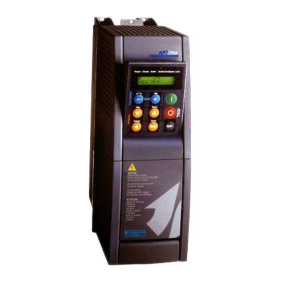
5.4 Keypad Operation The keypad (Fig. 5.4.1) is made of a LCD display with two 16-digit lines, seven LEDs and nine function keys. It is used: to start and stop the drive (this function can be disabled) to increase/decrease speed and jog to display the speed, voltage, diagnostics etc. - Page 80 Control [Text reference] - Function keys [START] Start key command used to start the drive via keypad; C00.20 - Commands select = [4] I/ O keys parameter setting and +24V between 12 & 13 terminals are always required to initiate a start/stop command from keypad. [STOP] Stop key command used to stop the drive via keypad;...
-
Page 81: Power Up
5.4.2 Power Up Power up the drive. The drive will begin a self test and initialization procedure which will take approximately 10 seconds. During this period, the display will cycle through various indications. During this process, the below message will appear on the display and all LED’s will simultaneously blink one time: -Torque +Torque Alarm Enable ZeroSpeed Limit AC DRIVE... -
Page 82: Menu & Parameter Index Displaying
5.4.3 Menu & Parameter Index Displaying Main menu Main menu index STARTUP Enter Index submenu 1st level STARTUP Submenu 1st level Drv & Mot config Enter Index submenu 2nd level STARTUP Submenu 2nd level Drv data Enter Parameter index STARTUP B0B.00 Parameter Mains voltage... -
Page 83: Using Keypad Help
5.4.5 Using Keypad Help (Help is not avaible for some menu entries SHIFT + HELP Help max value DISPLAY A00.00 0.000 DISPLAY Output freq DISPLAY A00.01 Help min value 0.000 START UP Ramp ref Help mode ZUSWR ---11 ARTDrive V2 series - Instruction Manual Chapter 5 Quick Start Up Guide •... -
Page 84: Drive Menu - Main Level
5.4.6 Drive Menu - Main Level The menu visualisation is available in two mode set by B05.00 - Access level parameter (STARTUP menu): - Easy (default) only main parameters are shown - Full include all parameters DISPLAY Drive display variables STARTUP Initial commissioning configurations Commands and... -
Page 85: Quick Start-Up Procedure
5.5 Quick Start-up Procedure Step Operation Description Go to the menu B STARTUP Scroll drive menus using t key, until STARTUP menu. If required: B STARTUP / B00 Drv & Mot config set drive regulation Enter the B0A.00 - Regulation mode parameter mode (defult is to set a different regulation mode: [1] V/f control, [2] FOC control and [3] SLS control . - Page 86 Step Operation Operation B STARTUP / B00 Drv & Mot config / B0E Autotune Run Motor autotune Select one of two Autotune procedures available: (Motor parameters • B0E.00 - Complete rot : complete self-tuning of drive measurement) current and flux loops with moving motor shaft. •...
- Page 87 Step Operation Operation B STARTUP / B02 Ref src Set the drive main Enter the B02.00 - Ramp ref 1 src parameter to select reference from the list displayed the source of drive speed reference; selection example: • 004 - AI 1 output Analog input 1 reference (default) •...
-
Page 88: Motor Potentiometer And Jog
5.5.1 Motor Potentiometer and Jog Run the motor using Motopot function This function is enabled in the standard settings with a Speed Reference value = 1000rpm. Verify B STARTUP / B01 Main cmds / B01.00 - Command select = [4] I/O keys. -
Page 89: Additional Information (Configuration Of The Ok Relay)
5.6 Additional Information (Configuration of the OK Relay) 5.6.1 Analog Input Tuning On the regulation card, the following configuration can be set: Input signal Analog inputs -10V…+10V 0-20mA 0-10V 4-20 mA Analog input 1 S8 = OFF S8 = ON Analog input 2 S9 = OFF S9 = ON... -
Page 90: Configuration Of The Ok Relay
Tune Analog input 1 gain C INTERFACE / C01 An Inp 1 Refer to maximum the position of the potentiometer connected to Analog input 1 terminals. Enter the C01.19 - AI 1 gain tune parameter: "Start…" message will be displayed, than press [Enter] key to run the procedure. -
Page 91: Encoder Verification
5.7 Encoder Verification Set the Drive in V/f control and run the motor, enable and start the drive and set a positive reference. The motor should be turning clockwise, looking at the driving shaft pointing at you. Monitor the encoder measurement in the following menu path: Encoder speed displaying A DISPLAY / A13 Adv Dsply Enter A13.02 - Act Std enc spd parameter to read encoder speed... - Page 92 92 • Chapter 5 Quick Start Up Guide ARTDrive V2 series - Instruction Manual...
-
Page 93: Chapter 6 - Parameter Description
Chapter 6 - Parameter Description 6.1 General Considerations The menu visualization is available in two mode set by Access level parameter (STARTUP menu): Easy (default) only main parameters are shown include all parameters (Easy + Full) Full See Level column on chapter X, Parameters: MENU MENU MENU... - Page 94 Example Block: Parameter An out 1 hi lim Input selected Variable An out 1 src An out 1 mon Parameter Parameter An out 1 scale An out 1 lo lim This chapter describes: • Variable connection methods • Block functions •...
-
Page 95: Block Functions
* -1 Terminal input Analog input 1 Block Ai1 output * +1 AI 1 alt value NULL AI 1 sgn src NULL AI 1 alt sel src Ramp ref 1 src Ramp setpoint Ramp Setpoint Block NULL Ramp ref inv src C01.00 - AI 1 alt sel src source allows you to select the signal to enable an alternative output reference. - Page 96 it connects the signal to Zero, Non-active 000-Null it connects the signal to One, Active 001-One ………… ………… it connects the signal to the standard digital input 003-DI 1 mon 1, being active or non-active is a function of the digital input state …………...
- Page 97 Analog signal Let’s consider a section of the Speed Block. In SPEED REG / Speed ref menu the source F00.00 - Speed ref 1 src selects the signal origin to the Speed block input. Creating the Speed reference. By editing the source the pick-list of the signal possible sources is displayed.
- Page 98 Speed setpoint Block example Dig speed ref 1 [rpm] Dig speed ref 1 Speed setpoint Ramp out Pick List 09 ....Speed ref 1 mon 000-DigSpd Ref 1 ....Speed ref 1 src 001-NULL 002-ONE 003-Gen output 004-AI 1 output 005-AI 2 output 006-AI 3 output ......
-
Page 99: Signal Normalization
6.1.3 Signal Normalization This paragraph describes the relationship between the physical units (rpm, Nm, A etc) and the Drive internal values. The different values which can be read via process channels are stated through an internal value (Count value) and the corresponding physical unit or parameter containing the reference value (Parameter name or Physical unit value). - Page 100 Parameter Name Normalized Normalized Physical value W0 comp out 2116 W1 comp out 9356 Ramp setpoint 7034 16384 Full scale speed Ramp out mon 8022 16384 Full scale speed Speed setpoint 7047 16384 Full scale speed Speed Draw out 7099 16384 Full scale speed Jog output...
- Page 101 Table 2 : Voltage Scale values (Volts = 16384 count) Mains voltage Voltage = 16384 count 230 V 217.5 V 380 V 378.3 V 400 V 378.3 V 415 V 378.3 V 440 V 435.1 V 460 V 435.1 V 575 V (only for 575V series) 543.91 V Table 3: Speed Reference...
-
Page 102: Parameter Legend
6.2 Parameter Legend MENU MENU MENU MENU MENU Index [Unit] Access Default Min/Max Format Reg.Mode Level Ipa Parameter Name Description DISPLAY This menu displays a series of variables useful to check the Drive state. The variable function is clearly explained by the variable name. Some of them are not applicable to all the different regulation modes. -
Page 103: Adisplay
MENU MENU MENU MENU MENU Index [Unit] Access Default Min/Max Format Reg.Mode Level Ipa Parameter Name Description DISPLAY This menu displays a series of variables useful to check the Drive state. The variable function is clearly explained by the variable name. Some of them are not applicable to all the different regulation modes. - Page 104 MENU MENU MENU MENU MENU Index [Unit] Access Default Min/Max Format Reg.Mode Level Ipa Parameter Name Description A10.00 Start SM mon V-F-S Full Drive Start status. 0 OFF 1 ON A11.00 FStop SM mon V-F-S Full Drive FastStop status 0 OFF 1 ON A12 DISPLAY / IO Dsply A12.00 DI 7654321E...
- Page 105 MENU MENU MENU MENU MENU Index [Unit] Access Default Min/Max Format Reg.Mode Level Ipa Parameter Name Description A13.05 RG sensor temp [°C] 0.00 0.00/0.00 V-F-S Easy 9073 Temperature on the RV33 regulation card A13.06 IA sensor temp [°C] 0.00 0.00/0.00 V-F-S Easy 9095...
- Page 106 MENU MENU MENU MENU MENU Index [Unit] Access Default Min/Max Format Reg.Mode Level Ipa Parameter Name Description generated. A13.14 Drv OL accum % 0.00 0.00/0.00 V-F-S Full 1540 Drive Unit I2t overload accumulator. When 100% is reached Drv overload alarm is generated and output inverter current is reduced to drive continuous current.
- Page 107 MENU MENU MENU MENU MENU Index [Unit] Access Default Min/Max Format Reg.Mode Level Ipa Parameter Name Description [8] 15kW - 20Hp [10] 575V - 30Hp [9] 22kW - 25Hp [11] 575V - 40Hp [10] 30kW - 30Hp [12] 575V - 50Hp [11] 37kW - 40Hp [13] 575V - 60Hp [12] 45kW - 50Hp...
- Page 108 MENU MENU MENU MENU MENU Index [Unit] Access Default Min/Max Format Reg.Mode Level Ipa Parameter Name Description DISPLAY / Alarm log This function provides a list of last 30 drive trips or various system error messages. Together with cause indications also time and data information is provided. Alarm log message is referred to “Sys time - dd mm yy”...
-
Page 109: Bstartup
MENU MENU MENU MENU MENU Index [Unit] Access Default Min/Max Format Reg.Mode Level Ipa Parameter Name Description STARTUP The drive can control the motor in three different ways: V/f (VF), Field Oriented (FOC) and Sensorless vect (SLS). Start the process for the motor data automatic measuring. Automatic calculation of the flux and current loop gains according to the performed •... - Page 110 MENU Index [Unit] Access Default Min/Max Format Reg.Mode Level Ipa Parameter Name Description STARTUP / Drv & Mot config / Drv data B0B.00 Mains voltage V-F-S-B Easy The Voltage selections available are: [0] 230 V [1] 380 V [2] 400 V (*) Default for 400V Europe [3] 415 V [4] 440 V...
- Page 111 MENU MENU MENU MENU MENU Index [Unit] Access Default Min/Max Format Reg.Mode Level Ipa Parameter Name Description Example: if Full scale speed parameter changes from 1500rpm to 3000 rpm, Autotune must be repated. Interval Range 0 ... 2048 2049 ... 4096 4097 ...
- Page 112 MENU Index [Unit] Access Default Min/Max Format Reg.Mode Level Ipa Parameter Name Description For AVy... (230...480Vac): [0] Standard 400V [1] Standard 460V For AVy...-5 (575Vac): [0] Standard 575V [1] Standard 575V ! By selecting one of the two options, the motor standard parameters with 400V (or 460V) are loaded making reference to the used Drive size.
- Page 113 MENU MENU MENU MENU MENU Index [Unit] Access Default Min/Max Format Reg.Mode Level Ipa Parameter Name Description BOE.05 Autotune Result B0E.5A Measured Rs [ohm] RW Calc Calc/Calc V-F-S-B Full 2780 Value of the phase resistance detected on the stator of the motor. BOE.5B Measured DTL Calc 0/50...
- Page 114 MENU Index [Unit] Access Default Min/Max Format Reg.Mode Level Ipa Parameter Name Description B0E.5M Measured Flux Max [Wb] Calc 0.00 - V-F-S Full 2900 Value of the maximum Flux. STARTUP / Drv & Mot config / V/f cfg B0F.00 V/f voltage Motr Calc/Calc Easy...
- Page 115 MENU MENU MENU MENU MENU Index [Unit] Access Default Min/Max Format Reg.Mode Level Ipa Parameter Name Description STARTUP / Drv & Mot config / Encoders Motor Encoder Setup Encoder 1 Std Encoder XE1 connector Std enc type [1]Digital Std dig enc mode [0]FP mode Std Enc Spd Std enc pulses...
- Page 116 MENU Index [Unit] Access Default Min/Max Format Reg.Mode Level Ipa Parameter Name Description B0G.02 Std enc supply V-F-S-B Easy 1927 [0] 5.41 / 8.16 V [1] 5.68 / 8.62 V [2] 5.91 / 9.00 V [3] 6.16 / 9.46 V Selection between 5V / 8V range is done through dip-switch S28.
- Page 117 MENU MENU MENU MENU MENU Index [Unit] Access Default Min/Max Format Reg.Mode Level Ipa Parameter Name Description setting: B0G.07 - Dig spd Fbk Sel (Ipa 1940). Pick List 22 B0G.09 Rep/Sim enc sel Full 1962 Selection of the encoder to be repeated using the optional card EXP-F2E: [0] Repeat StdEnc Repeat standard encoder [1] Repeat ExpEnc...
- Page 118 MENU Index [Unit] Access Default Min/Max Format Reg.Mode Level Ipa Parameter Name Description ! Digital inputs 6 and 7 (terminals 38 and 39) are dedicated to the use of the “Index Qualifier” (home position switch) when Index storing is enabled. In the next table are showed the values of B0G.12 - IS ctrl src from SBI word, APC word or B0G.12 - Int IS ctrl if: B0G.12 - IS ctrl src = B0G.11 - Int IS ctrl (Ipa 9551) Access...
- Page 119 MENU MENU MENU MENU MENU Index [Unit] Access Default Min/Max Format Reg.Mode Level Ipa Parameter Name Description STARTUP / Drv & Mot config / Mot ovld B0H.00 Mot service fact 0.5/1.5 V-F-S-B Easy 1611 Service factor. Some motors have a motor continuous current (Ic) higher than the rated current (In).
- Page 120 MENU Index [Unit] Access Default Min/Max Format Reg.Mode Level Ipa Parameter Name Description STARTUP / Drv & Mot config / BU olvd The function protects braking resistor by monitoring current in the resistor according to I2t characteristic. When the protection becomes active, it is possible to generate an alarm condition.
- Page 121 MENU MENU MENU MENU MENU Index [Unit] Access Default Min/Max Format Reg.Mode Level Ipa Parameter Name Description Resistor short time overload rating = 5 time quarter minute (5 time continuous amps for 15 secs) Set parameters: Bu resistance Bu res cont pwr 11.25 kW (15 * 50) Bu res OL time...
- Page 122 MENU Index [Unit] Access Default Min/Max Format Reg.Mode Level Ipa Parameter Name Description STARTUP / Main cmds B01.00 Commands select V-F-S-B Easy 4002 [0] TerminalLevel The drive is controlled via terminal strip using Level sensitive signals [1] TerminalEdge The drive is controlled via terminal strip using Edge sensitive signals [2] DigitalLevel The drive is controlled from a communication or application card using level sensitive signals...
- Page 123 MENU MENU MENU MENU MENU Index [Unit] Access Default Min/Max Format Reg.Mode Level Ipa Parameter Name Description B01.02 Stop key mode V-F-S-B Easy 3998 Stop key configuration: [0] Inactive (*): Default for Europe Standard configuration, where main commands are coming from keypad. Therefore, the STOP key will cause a normal stop of the motor.
- Page 124 MENU Index [Unit] Access Default Min/Max Format Reg.Mode Level Ipa Parameter Name Description B05.00 B05.00 Access level V-F-S Easy It allows the Easy or Full parameter inverter menu/parameters visualization: [0] Easy Partially inverter menu/parameters visualization [1] Full Totally inverter menu/parameters visualization Chapter 6 Parameter •...
-
Page 125: Cinterface
MENU MENU MENU MENU MENU Index [Unit] Access Default Min/Max Format Reg.Mode Level Ipa Parameter Name Description INTERFACE INTERFACE / Commands For starting, the drive always requires the Enable command, Start command and Fast stop when enabled. The above different commands affect the drive rotation: This command unlocks power converter firing. - Page 126 MENU MENU MENU MENU MENU Index [Unit] Access Default Min/Max Format Reg.Mode Level Ipa Parameter Name Description Usage of this command is optional. This command is used when the drive Fast stop is operated with Ramp and speed regulation. When the command is active, the Ramp input reference is zeroed and the ramp operates on a specific deceleration slope that can be set independently from the standard deceleration slope.
- Page 127 MENU MENU MENU MENU MENU Index [Unit] Access Default Min/Max Format Reg.Mode Level Ipa Parameter Name Description Spd 0 dis dly Term Local src 1000 ms Terminals NULL DI 0 En mon En/Disable mode [1]Stop/FSSpd=0 Digital Dig Enable src NULL I O Keys Press O IOKeys...
- Page 128 MENU MENU MENU MENU MENU Index [Unit] Access Default Min/Max Format Reg.Mode Level Ipa Parameter Name Description C00.02 Term Stop src Ipa4000 PList 16 V-F-S-B Full 9211 Ipa 4000 - NULL = Default It allows to select the signal to generate the terminal strip Stop command. Pick List 16 ! Signal active only when “C00.20 - Commands select = [1] TerminalEdge The Start and Stop commands can be controlled, as an alternative, via:...
- Page 129 MENU MENU MENU MENU MENU Index [Unit] Access Default Min/Max Format Reg.Mode Level Ipa Parameter Name Description The status of the digital selector is read by the drive only when the output of the inverter bridge is disabled. As a result, it is not possible to switch between local and remote source for main commands while the motor is running.
- Page 130 MENU MENU MENU MENU MENU Index [Unit] Access Default Min/Max Format Reg.Mode Level Ipa Parameter Name Description Pick List 3 C00.09 Stop src Plist 03 V-F-S-B Easy 8085 (*) Ipa 4001 - ONE = Default (Europe) Ipa 4023 - DI 3 = Default (American) It allows to select the signal Stop command of 3-wires;...
- Page 131 MENU MENU MENU MENU MENU Index [Unit] Access Default Min/Max Format Reg.Mode Level Ipa Parameter Name Description C00.24 Stop key mode V-F-S-B Easy 3998 Stop key configuration (valid for Command select ≠ [I-O] keys only) : [0] Inactive (*): Default for Europe Standard configuration, where main commands are coming from keypad.
- Page 132 MENU MENU MENU MENU MENU Index [Unit] Access Default Min/Max Format Reg.Mode Level Ipa Parameter Name Description C00-07 Forward Start src C00-08 Reverse src C00-26 FRC reverse C00-27 FRC alarm = no change Figure C00.25-1: C.00.25= [0] FRC control: Run command and Reverse command C00-07 Forward Start src C00-08 Reverse src C00-28 FRC Str mon...
- Page 133 MENU MENU MENU MENU MENU Index [Unit] Access Default Min/Max Format Reg.Mode Level Ipa Parameter Name Description C00.26 FRC reverse V-F-S-B Easy 8081 It displays the output reverse signal of FRC block C00.27 FRC alarm V-F-S-B Easy 8082 It displays the output Alarm signal of FRC block C00.28 FRC Start mon V-F-S-B Easy...
- Page 134 MENU MENU MENU MENU MENU Index [Unit] Access Default Min/Max Format Reg.Mode Level Ipa Parameter Name Description INTERFACE / Analog Inputs The Drive, in its standard version on the regulation card, provides the following analog/ digital I/Os: 3 analog inputs (terminals: 1-2, 3-4, 5-6), configured as voltage or current differential inputs.
- Page 135 MENU MENU MENU MENU MENU Index [Unit] Access Default Min/Max Format Reg.Mode Level Ipa Parameter Name Description Input 1 signal. Pick List 3 C01.01 AI 1 alt sel src Ipa4000 PList 3 V-F-S-B Full 5012 Ipa 4000 - NULL = Default It connects the selected signal to the selector of the alternative reference for An.
- Page 136 MENU MENU MENU MENU MENU Index [Unit] Access Default Min/Max Format Reg.Mode Level Ipa Parameter Name Description C01.14 AI 1 offset -100/100 V-F-S-B Easy 5001 Analog Input 1 offset count value 100% is equal to 10V or 20mA. C01.15 AI 1 filter [sec] 0.0064 0.00/4.096...
- Page 137 MENU MENU MENU MENU MENU Index [Unit] Access Default Min/Max Format Reg.Mode Level Ipa Parameter Name Description C01.22 AI 1 gain -16/16 V-F-S-B Full 5005 Analog Input 1 gain count value displaying. How to perform the self-tuning procedure of the Analog input 1, if the input is -10V/ +10V (factory).
- Page 138 MENU MENU MENU MENU MENU Index [Unit] Access Default Min/Max Format Reg.Mode Level Ipa Parameter Name Description C02 INTERFACE / An Inp 2 See Analog Input 1 diagram and description details above. C02.00 AI 2 sgn src Ipa4000 PList 3 V-F-S-B Full 5031...
- Page 139 MENU MENU MENU MENU MENU Index [Unit] Access Default Min/Max Format Reg.Mode Level Ipa Parameter Name Description C02.15 AI 2 filter [sec] 0.0064 0.00/4.096 V-F-S-B Full 5026 Time constant of the Analog Input 2 filter. C02.16 AI 2 low lim [cnt] -16384 -32768/32767 PP...
- Page 140 MENU MENU MENU MENU MENU Index [Unit] Access Default Min/Max Format Reg.Mode Level Ipa Parameter Name Description C03.01 AI 3 alt sel src Ipa4000 PList 3 V-F-S-B Full 5052 Ipa 4000 - NULL = Default It connects the selected signal to the selector of the alternative reference for An. Inp. 3 block.
- Page 141 MENU MENU MENU MENU MENU Index [Unit] Access Default Min/Max Format Reg.Mode Level Ipa Parameter Name Description C03.18 AI 3 offs tune / Start? Autotune command for the Analog Input 3 offset. Input automatic fine-tuning. To run the autotune, put the input signal to its minimum value and execute “Start ?” command C03.19 AI 3 gain tune / Start? Autotune command for the Analog Input 3 gain.
- Page 142 MENU MENU MENU MENU MENU Index [Unit] Access Default Min/Max Format Reg.Mode Level Ipa Parameter Name Description INTERFACE / An Inp 1X This Block refers to possible Option Expansion cards. See the considerations listed in the previous paragraph, including the parameter description. The points of difference are: •...
- Page 143 MENU MENU MENU MENU MENU Index [Unit] Access Default Min/Max Format Reg.Mode Level Ipa Parameter Name Description C05.13 AI 1X offset -100/100 V-F-S-B Full 5061 Analog Input 1X offset count value 100% is equal to 10V or 20mA. C05.14 AI 1X low lim [cnt] -16384 -32768/32767 PP...
- Page 144 MENU MENU MENU MENU MENU Index [Unit] Access Default Min/Max Format Reg.Mode Level Ipa Parameter Name Description C06.10 AI 2X type V-F-S-B Full 5080 [0] -10V .. +10V As for “ AI 1 type” parameter description above [1] 0.20mA,0.10V As for “ AI 1 type” parameter description above [2] 4..20mA As for “...
- Page 145 MENU MENU MENU MENU MENU Index [Unit] Access Default Min/Max Format Reg.Mode Level Ipa Parameter Name Description C06.23 AI 2X gain -16/16 V-F-S-B Full 5084 Analog Input 2X gain count value displaying. INTERFACE / AI dest “Analog Inputs destinations” is a read-only menu, which allows the user to see where the analog inputs are connected.
- Page 146 MENU MENU MENU MENU MENU Index [Unit] Access Default Min/Max Format Reg.Mode Level Ipa Parameter Name Description INTERFACE / Analog Outputs Drive has 2 standard voltage outputs and 4 expanded analog outputs (1x and 2x = voltage outputs, 3x and 4x=current outputs). The Blocks of the analog outputs allow to turn an internal signal into a voltage signal (or a current signal if the EXP-D20A6 option card is used) available on the terminal strip.
- Page 147 MENU MENU MENU MENU MENU Index [Unit] Access Default Min/Max Format Reg.Mode Level Ipa Parameter Name Description INTERFACE / An Out 2 See Analog Otuput 1 diagram and description details above. C09.00 AO 2 src Ipa4000 PList 2 V-F-S-B Easy 3580 Ipa 4000 - NULL = Default It allows to connect the selected signal to the Analog output 2.
- Page 148 MENU MENU MENU MENU MENU Index [Unit] Access Default Min/Max Format Reg.Mode Level Ipa Parameter Name Description C11.10 AO 1X scale 1 -10 V-F-S-B Full 6022 Scale or multiplicative factor of Analog output 1X C11.11 AO 1X high lim [cnt] 16383 0/32767 V-F-S-B...
- Page 149 MENU MENU MENU MENU MENU Index [Unit] Access Default Min/Max Format Reg.Mode Level Ipa Parameter Name Description INTERFACE / An Out 3X See Analog Output 1 diagram and description above. ! This output is current type. C13.00 AO 3X src Ipa4000 PList 2 V-F-S-B...
- Page 150 MENU MENU MENU MENU MENU Index [Unit] Access Default Min/Max Format Reg.Mode Level Ipa Parameter Name Description Pick List 2 C14.10 AO 4X type V-F-S-B Full 6039 It allows to select the Analog output 4X type (EXP-D20A6 optional card is required); below are shown the selections: [0] 0..20 mA [1] 4..20 mA...
- Page 151 MENU MENU MENU MENU MENU Index [Unit] Access Default Min/Max Format Reg.Mode Level Ipa Parameter Name Description INTERFACE / Digital Inputs The Blocks of the digital inputs allow to turn a signal available on the terminal strip into an internal signal. As described before, the output of the blocks is included in the lists for the selection of the different sources (src).
- Page 152 MENU MENU MENU MENU MENU Index [Unit] Access Default Min/Max Format Reg.Mode Level Ipa Parameter Name Description INTERFACE / DI Cfg C15.00 DI 1 inversion V-F-S-B Easy 4011 [0] Not inverted [1] Inverted C15.01 DI 2 inversion V-F-S-B Easy 4012 [0] Not inverted [1] Inverted C15.02 DI 3 inversion...
- Page 153 MENU MENU MENU MENU MENU Index [Unit] Access Default Min/Max Format Reg.Mode Level Ipa Parameter Name Description INTERFACE / DI ExpCfg See Digital inputs diagram and description above. C17.00 DI 0X inversion V-F-S-B Full 4030 [0] Not inverted [1] Inverted C17.01 DI 1X inversion V-F-S-B Full...
- Page 154 MENU MENU MENU MENU MENU Index [Unit] Access Default Min/Max Format Reg.Mode Level Ipa Parameter Name Description C17.09 DI 9X inversion V-F-S-B Easy 4039 [0] Not inverted [1] Inverted C17.10 DI 10X inversion V-F-S-B Easy 4040 [0] Not inverted [1] Inverted C17.11 DI 11X inversion V-F-S-B Easy...
- Page 155 MENU MENU MENU MENU MENU Index [Unit] Access Default Min/Max Format Reg.Mode Level Ipa Parameter Name Description INTERFACE / Digital inputs destination This read-only menu allows the user to see where the Digital inputs are connected. If more then one source is connected to the Digital Input, only first one is shown. If no sources are connected the message “Not used”...
- Page 156 MENU MENU MENU MENU MENU Index [Unit] Access Default Min/Max Format Reg.Mode Level Ipa Parameter Name Description C18.10 DI 2X dest 4047 It displays the Digital Input 2X destination. C18.11 DI 3X dest 4048 It displays the Digital Input 3X destination. C18.12 DI 4X dest 4049 It displays the Digital Input 4X destination.
- Page 157 MENU MENU MENU MENU MENU Index [Unit] Access Default Min/Max Format Reg.Mode Level Ipa Parameter Name Description INTERFACE / Digital outputs The blocks of the digital outputs allow to turn an internal signal into a signal available on the terminal strip. Exp dig out en DO 0 src Disabled...
- Page 158 MENU MENU MENU MENU MENU Index [Unit] Access Default Min/Max Format Reg.Mode Level Ipa Parameter Name Description There are no failure alarms present The drive is enabled. The enable operation is defined by parameters En/disable mode & Commands sel The magnetizing procedure has been completed (Drive is ready to deliver torque) ! The contact opens immediately on a drive failure, or when the drive is disabled.
- Page 159 MENU MENU MENU MENU MENU Index [Unit] Access Default Min/Max Format Reg.Mode Level Ipa Parameter Name Description C19.01 DO 1 src Ipa3728 PList 1 V-F-S-B Easy 4066 Ipa 3730 - [43] Spd is dly = Default It allows to connect the selected signal to the Digital output 1. Pick List 1 C19.02 DO 2 src Ipa4000...
- Page 160 MENU MENU MENU MENU MENU Index [Unit] Access Default Min/Max Format Reg.Mode Level Ipa Parameter Name Description C20.00 C20.00 Exp DO enable V-F-S-B Full 3903 It enables the expanded digital outputs: [0] Disabled [1] Enabled INTERFACE / DO ExpCfg See Digital outputs diagram and description above. C21.00 DO 0X src Ipa4000 PList 1...
- Page 161 MENU MENU MENU MENU MENU Index [Unit] Access Default Min/Max Format Reg.Mode Level Ipa Parameter Name Description C21.05 DO 5X src Ipa4000 PList 1 V-F-S-B Full 4085 Ipa 4000 - NULL = Default It allows to connect the selected signal to the Digital output 5X. Pick List 1 C21.06 DO 6X src Ipa4000...
- Page 162 MENU MENU MENU MENU MENU Index [Unit] Access Default Min/Max Format Reg.Mode Level Ipa Parameter Name Description C21.15 DO 5X inversion V-F-S-B Full 4075 [0] Not inverted [1] Inverted C21.16 DO 6X inversion V-F-S-B Full 4076 [0] Not inverted [1] Inverted C21.17 DO 7X inversion V-F-S-B Full...
- Page 163 MENU MENU MENU MENU MENU Index [Unit] Access Default Min/Max Format Reg.Mode Level Ipa Parameter Name Description INTERFACE / Bit->Word The Word Composing Block, “Bits->Word”, is useful to communicate, for example, between Drive and APC option card or Drive and Field Bus option card. This block allows the user to compose a word made of Drive ready, Drive ok, Ref is zero, Speed is zero, by communicating on a single word.
- Page 164 MENU MENU MENU MENU MENU Index [Unit] Access Default Min/Max Format Reg.Mode Level Ipa Parameter Name Description C22.03 Word0 B3 src Ipa4000 PList 1 V-F-S-B Full 2103 Ipa 4000 - NULL = Default It allows to connect the Bit 3 signal selected to the Word 0. Pick List 1 C22.04 Word0 B4 src Ipa4000...
- Page 165 MENU MENU MENU MENU MENU Index [Unit] Access Default Min/Max Format Reg.Mode Level Ipa Parameter Name Description C22.09 Word0 B9 src Ipa4000 PList 1 V-F-S-B Full 2109 Ipa 4000 - NULL = Default It allows to connect the Bit 9 signal selected to the Word 0. Pick List 1 C22.10 Word0 B10 src Ipa4000...
- Page 166 MENU MENU MENU MENU MENU Index [Unit] Access Default Min/Max Format Reg.Mode Level Ipa Parameter Name Description C22.15 Word0 B15 src Ipa4000 PList 1 V-F-S-B Full 2115 Ipa 4000 - NULL = Default It allows to connect the Bit 15 signal selected to the Word 0. Pick List 1 C22.20 W0 comp out V-F-S-B...
- Page 167 MENU MENU MENU MENU MENU Index [Unit] Access Default Min/Max Format Reg.Mode Level Ipa Parameter Name Description C22.35 Word1 B5 src Ipa4000 PList 1 V-F-S-B Full 9345 Ipa 4000 - NULL = Default It allows to connect the Bit 5 signal selected to the Word 1. Pick List 1 C22.36 Word1 B6 src Ipa4000...
- Page 168 MENU MENU MENU MENU MENU Index [Unit] Access Default Min/Max Format Reg.Mode Level Ipa Parameter Name Description C22.41 Word1 B11 src Ipa4000 PList 1 V-F-S-B Full 9351 Ipa 4000 - NULL = Default It allows to connect the Bit 11 signal selected to the Word 1. Pick List 1 C22.42 Word1 B12 src Ipa4000...
- Page 169 MENU MENU MENU MENU MENU Index [Unit] Access Default Min/Max Format Reg.Mode Level Ipa Parameter Name Description INTERFACE / Word->Bit The Word Decomposing Block, “Word->Bits”, allows to set some signals on a digital word; each signal composing the word, on the Block input, can be combined with an output channel.
- Page 170 MENU MENU MENU MENU MENU Index [Unit] Access Default Min/Max Format Reg.Mode Level Ipa Parameter Name Description C23.22 B2 W0 decom V-F-S-B Full 2125 Bit 2 of Word 0 decomposed displaying. C23.23 B3 W0 decom V-F-S-B Full 2126 Bit 3 of Word 0 decomposed displaying. C23.24 B4 W0 decom V-F-S-B Full...
- Page 171 MENU MENU MENU MENU MENU Index [Unit] Access Default Min/Max Format Reg.Mode Level Ipa Parameter Name Description C23.34 B14 W0 decom V-F-S-B Full 2137 Bit 14 of Word 0 decomposed displaying. C23.35 B15 W0 decom V-F-S-B Full 2138 Bit 15 of Word 0 decomposed displaying. C23.40 W1 decom src Ipa9360 PList 27...
- Page 172 MENU MENU MENU MENU MENU Index [Unit] Access Default Min/Max Format Reg.Mode Level Ipa Parameter Name Description C23.66 B6 W1 decom V-F-S-B Full 9369 Bit 6 of Word 1 decomposed displaying. C23.67 B7 W1 decom V-F-S-B Full 9370 Bit 7 of Word 1 decomposed displaying. C23.68 B8 W1 decom V-F-S-B Full...
-
Page 173: Dref&Ramp
MENU MENU MENU MENU MENU Index [Unit] Access Default Min/Max Format Reg.Mode Level Ipa Parameter Name Description REF&RAMP REF&RAMP / Ramp ref Speed ref 1 mon MULTIRAMP Ramp ref 3 mon Speed ratio mon Ramp ref 2 mon MltRamp Speed ref 2 mon Ramp ref 1 mon Speed Ramp... - Page 174 MENU MENU MENU MENU MENU Index [Unit] Access Default Min/Max Format Reg.Mode Level Ipa Parameter Name Description Avoid ref 1 0 rpm Avoid ref 2 0 rpm Avoid band 1 Avoid band 2 0 rpm 0 rpm Ramp ref 1 src AI 1 output Ramp ref 1 mon DigRampRef 1...
- Page 175 MENU MENU MENU MENU MENU Index [Unit] Access Default Min/Max Format Reg.Mode Level Ipa Parameter Name Description D00.03 Ramp ref inv src Ipa4000 PList 3 V-F-S-B Easy 7037 Ipa 4000 - NULL = Default It connects the selected signal to the selector of the multiplier input: if the signal is 0, multiply by +1, or if the signal is 1, multiply by –1.
- Page 176 MENU MENU MENU MENU MENU Index [Unit] Access Default Min/Max Format Reg.Mode Level Ipa Parameter Name Description REF&RAMP / MRamp src This Block allows to select 4 different sets of the Ramp times. Each ramp time set allows to set the acceleration and deceleration times of the Ramp and of the S-Ramp and the deceleration time of the Fast Stop.
- Page 177 MENU MENU MENU MENU MENU Index [Unit] Access Default Min/Max Format Reg.Mode Level Ipa Parameter Name Description D01.01 Mlt ramp s1 src Ipa4000 PList 3 V-F-S-B Easy 8091 Ipa 4000 - NULL = Default Multi ramp selector 1 source: it allows to select the origin of the signals stating the input combination.
- Page 178 MENU MENU MENU MENU MENU Index [Unit] Access Default Min/Max Format Reg.Mode Level Ipa Parameter Name Description REF&RAMP / MRampSet1 D02.00 Accel time 1 [sec] 0.5/10000 V-F-S-B Easy 8041 Acceleration ramp time 1. D02.01 Decel time 1 [sec] 0.5/10000 V-F-S-B Easy 8043 Deceleration ramp time 1.
- Page 179 MENU MENU MENU MENU MENU Index [Unit] Access Default Min/Max Format Reg.Mode Level Ipa Parameter Name Description D04.02 F dec time 3 [sec] 0.5/10000 V-F-S-B Easy 8065 Fast Stop deceleration ramp time 3. D04.03 Acc S curve 3 [sec] Calc/Calc V-F-S-B Easy 8066...
- Page 180 MENU MENU MENU MENU MENU Index [Unit] Access Default Min/Max Format Reg.Mode Level Ipa Parameter Name Description REF&RAMP / RampFunct The Function of this Block is to generate the Ramped Speed reference. Such signal is generated by tracking the reference of the Ramp setpoint block with the Ramp times defined in the Multi ramp block.
- Page 181 MENU MENU MENU MENU MENU Index [Unit] Access Default Min/Max Format Reg.Mode Level Ipa Parameter Name Description D07.10 Ramp out enable V-F-S-B Easy 8031 [0] Disabled [1] Enabled Ramp function enabling D07.11 Ramp shape V-F-S-B Easy 8021 [0] Linear [1] S-Shaped Ramp selection.
- Page 182 MENU MENU MENU MENU MENU Index [Unit] Access Default Min/Max Format Reg.Mode Level Ipa Parameter Name Description REF&RAMP / Mlt speed This Block allows to set up to 8 Internal Speed references, one of which is supplied with the Speed 0 reference function. Three selection inputs allow to activate on the output the desired Speed.
- Page 183 MENU MENU MENU MENU MENU Index [Unit] Access Default Min/Max Format Reg.Mode Level Ipa Parameter Name Description REF&RAMP / Mlt speed D08.00 MltSpd sel 0 src Ipa4000 PList 3 V-F-S-B Easy 7072 Ipa 4000 - NULL = Default Multi speed 1 selector source: it allows to select the origin of the signals stating the input combination.
- Page 184 MENU MENU MENU MENU MENU Index [Unit] Access Default Min/Max Format Reg.Mode Level Ipa Parameter Name Description D08.11 Mlt spd 1 [rpm] 0.00 Calc/Calc V-F-S-B Easy 7061 Digital Multi Speed 1 value D08.12 Mlt spd 2 [rpm] 0.00 Calc/Calc V-F-S-B Easy 7062 Multi Speed 2 value.
- Page 185 MENU MENU MENU MENU MENU Index [Unit] Access Default Min/Max Format Reg.Mode Level Ipa Parameter Name Description REF&RAMP / Motopot The Motopotentiometer function is enabled in the standard settings. Furthermore, through the D09.00 - Mpot up src and D09.01 - Mpot down src sources it is possible to select the origin of the Speed increase and decrease and of the command signals.
- Page 186 MENU MENU MENU MENU MENU Index [Unit] Access Default Min/Max Format Reg.Mode Level Ipa Parameter Name Description REF&RAMP / Motopot D09.00 Mpot up src Ipa4000 PList 3 V-F-S-B Easy 7091 Ipa 4000 - NULL = Default It allows to select the origin of the signals of Motopot up command. Pick List 3 D09.01 Mpot down src Ipa4000...
- Page 187 MENU MENU MENU MENU MENU Index [Unit] Access Default Min/Max Format Reg.Mode Level Ipa Parameter Name Description D09.14 Mpot init cfg V-F-S-B Easy 7086 Motopot initial configuration: [0] Power off Value at turning off [1] Zero Zero rpm [2] Lower limit Lower limit value [3] Upper limit Upper limit value...
- Page 188 MENU MENU MENU MENU MENU Index [Unit] Access Default Min/Max Format Reg.Mode Level Ipa Parameter Name Description REF&RAMP / Jog This block states the Speed reference of the Jog Function. It is possible to set 4 Jog speeds: Jog 0, Jog 1, Jog 2 and Jog 3. The output desired speed can be activated according to the state of the selection inputs D10.00 - Jog sel 0 src and D10.02 - Jog sel 1 src.
- Page 189 MENU MENU MENU MENU MENU Index [Unit] Access Default Min/Max Format Reg.Mode Level Ipa Parameter Name Description REF&RAMP / Jog D10.00 Jog sel 0 src Ipa8000 PList12 V-F-S-B Easy 8014 Ipa 8000 - Jog 0 = Default It allows to select the origin of Jog 0 speed reference value. Pick List 12 D10.01 Jog cmd src Ipa4000...
- Page 190 MENU MENU MENU MENU MENU Index [Unit] Access Default Min/Max Format Reg.Mode Level Ipa Parameter Name Description D10.13 Jog 3 [rpm] RWS 100.00 0.00/- V-F-S-B Full 8003 Digital Jog speed 4 value D10.14 Jog acc Time [sec] 0.5/10000 V-F-S-B Easy 8005 Acceleration Jog ramp time.
- Page 191 MENU MENU MENU MENU MENU Index [Unit] Access Default Min/Max Format Reg.Mode Level Ipa Parameter Name Description REF&RAMP / Jump Ref The block function operates the motor while avoiding resonance caused by characteristic frequency references in the customer system machine. Parameters function allow to set two jump reference frequencies in rpm, with their related jump bandwidth in rpm too.
- Page 192 MENU MENU MENU MENU MENU Index [Unit] Access Default Min/Max Format Reg.Mode Level Ipa Parameter Name Description D11.03 Jump Band 2 [rpm] RWS 0/(**) V-F-S-B Easy Jump bandwidth 2 frequency in rpm. (**) Maximum value setting allowed is equal to: a) 100 if FSS>100 b) FSS if FSS<100 FSS = B01.00 - Full scale speed (Ipa 1885).
-
Page 193: Ereg Param
MENU MENU MENU MENU MENU Index [Unit] Access Default Min/Max Format Reg.Mode Level Ipa Parameter Name Description REG PARAM According to the chosen regulation mode, some control loops could be inactive. The following table states (with X) which are the active loops corresponding to each different mode: Speed loop Current loop... - Page 194 MENU MENU MENU MENU MENU Index [Unit] Access Default Min/Max Format Reg.Mode Level Ipa Parameter Name Description E00.06 Spd P base value [A/rpm] RWS Calc 0.00/Calc F-S-B Full 2075 Basic value of the proportional gain of speed loop. E00.07 Spd I base value [A/rpm/s] RWS Calc 0.00/Calc F-S-B...
- Page 195 MENU MENU MENU MENU MENU Index [Unit] Access Default Min/Max Format Reg.Mode Level Ipa Parameter Name Description E02.03 Flx I base value [A/Wb/s] RWS Calc 0.00/Calc Full 2022 Basic value of the integral gain of flux loop. REG PARAM / Volt Reg ! Menu accessible with Access Level = FULL.
- Page 196 MENU MENU MENU MENU MENU Index [Unit] Access Default Min/Max Format Reg.Mode Level Ipa Parameter Name Description REG PARAM / DeadTime ! Menu accessible with Access Level = FULL The Dead time comp function allows for compensation of the output voltage distortion due to IGBT voltage drop and its switching characteristics.
- Page 197 MENU MENU MENU MENU MENU Index [Unit] Access Default Min/Max Format Reg.Mode Level Ipa Parameter Name Description REG PARAM / V/f Reg When the motor is loaded, the mechanical speed changes according to the applied load. In order to reduce the speed error, it is possible to compensate for the motor slip. The function parameterization allows: to increase the output voltage with low frequencies (voltage Boost) to compensate the speed change due to a load increase...
- Page 198 MENU MENU MENU MENU MENU Index [Unit] Access Default Min/Max Format Reg.Mode Level Ipa Parameter Name Description REG PARAM / V/f SaveE The function allows to reduce the motor Flux in order to reduce the losses. As a consequence it is possible to obtain an energy saving when the load requires a reduced torque as compared to the rated one (save energy).
- Page 199 MENU MENU MENU MENU MENU Index [Unit] Access Default Min/Max Format Reg.Mode Level Ipa Parameter Name Description E06.02 Dig SE flx level 10/100 Easy 3536 Digital value of V/f Save Energy Flux. E06.03 SE flx ramp time [sec] 0/100 Easy 3537 V/f Save Energy Flux Level ramp time value REG PARAM / VFAutCapt...
- Page 200 MENU MENU MENU MENU MENU Index [Unit] Access Default Min/Max Format Reg.Mode Level Ipa Parameter Name Description E07.06 Vlt search m Easy 3572 Displaying of the Voltage search state signal: 0 =Wait start function 1 = Wait demagnetization end 2 = Search in progress 3 = End search Chapter 6 Parameter •...
- Page 201 MENU MENU MENU MENU MENU Index [Unit] Access Default Min/Max Format Reg.Mode Level Ipa Parameter Name Description REG PARAM / VFAutCapt Automatic Restart after a Temporary Alarm “Retrying” Before the autocapture process starts, it is necessary to wait for the motor to be demagnetized in order to avoid high current transient due to the E.M.F.
- Page 202 MENU MENU MENU MENU MENU Index [Unit] Access Default Min/Max Format Reg.Mode Level Ipa Parameter Name Description REG PARAM / SLS FGain ! Menu accessible with Access Level = FULL The function is active only with a Sensorless mode. With a Sensorless mode the motor speed is estimated.
- Page 203 MENU MENU MENU MENU MENU Index [Unit] Access Default Min/Max Format Reg.Mode Level Ipa Parameter Name Description REG PARAM / SLS Fgain E08.00 Sls mot HPgain 0/100 Full 1090 Motor Proportional High gain. E08.01 Sls mot HIgain 0/100 Full 1091 Motor Integral High gain.
- Page 204 MENU MENU MENU MENU MENU Index [Unit] Access Default Min/Max Format Reg.Mode Level Ipa Parameter Name Description E08.20 Sls catch Pgain 0/100 Full 1181 Proportional speed feedback Sls gain during magnetization. E08.21 Sls catch Igain Full 1182 Integral speed feedback Sls gain during magnetization. E08.30 Sls H/M tran lev [rpm] Calc...
- Page 205 MENU MENU MENU MENU MENU Index [Unit] Access Default Min/Max Format Reg.Mode Level Ipa Parameter Name Description REG PARAM / Tst Gener ! Menu accessible with Access Level = FULL The tuning of the regulators is performed via an internal test signal generator in order to evaluate the regulator response.
- Page 206 MENU MENU MENU MENU MENU Index [Unit] Access Default Min/Max Format Reg.Mode Level Ipa Parameter Name Description Chapter 6 Parameter • 206 ARTDrive V2 series - Instruction Manual...
-
Page 207: Fspeed Reg
MENU MENU MENU MENU MENU Index [Unit] Access Default Min/Max Format Reg.Mode Level Ipa Parameter Name Description SPEED REG SPEED REG / Speed reference This function generates the reference of speed regulation block. It is obtained by algebracally adding on the input the references Speed ref 1 and Speed ref 2, the Ramp block output and the Jog block output. - Page 208 MENU MENU MENU MENU MENU Index [Unit] Access Default Min/Max Format Reg.Mode Level Ipa Parameter Name Description Switch is closed if Ramp out enable = Disabled & Stop Switch is closed if Ramp out enable = Disabled & (!FastStop) Switch is closed if Ramp out enable = Disabled & (FastStop) Both switches are closed if Ramp out enable = Enabled SPEED REG / Speed ref F00.00 Speed ref 1 src...
- Page 209 MENU MENU MENU MENU MENU Index [Unit] Access Default Min/Max Format Reg.Mode Level Ipa Parameter Name Description F00.11 Dig spd ref 2 [rpm] RWS Calc/Calc V-F-S-B Full 7041 Value of the Digital speed reference 2 variable, selectable through Pick List 10 of F00.01 - Speed ref 2 src.
- Page 210 MENU MENU MENU MENU MENU Index [Unit] Access Default Min/Max Format Reg.Mode Level Ipa Parameter Name Description SPEED REG / Speed ref Rubber Calender application example MASTER = 1000 rpm 1050 rpm 1100 rpm DRIVE A DRIVE C DRIVE B AN.
- Page 211 MENU MENU MENU MENU MENU Index [Unit] Access Default Min/Max Format Reg.Mode Level Ipa Parameter Name Description For count parameters of AI X lo lim e AI X hi lim to see chapter 6.1.3 Signal Normalization, or to use: hi lim for Line speed +5% 100% : 16384 = 105% : X lo lim for Line speed -5% 100% : 16384 =...
- Page 212 MENU MENU MENU MENU MENU Index [Unit] Access Default Min/Max Format Reg.Mode Level Ipa Parameter Name Description SPEED REG / Speed Regulator Config The Block Function, Regulator of the PI Speed (Proportional Integrative), is only active in a Sensorless and Field Oriented mode. Among its functions the Block is set to work together with the Speed/Torque regulation Block (OR regulator).
- Page 213 MENU MENU MENU MENU MENU Index [Unit] Access Default Min/Max Format Reg.Mode Level Ipa Parameter Name Description zero and stops its integrating activity. Pick List 3 F01.10 Spd reg enable RWSZ V-F-S-B Easy 7059 Enabling of the speed regulator: [0] Disabled [1] Enabled F01.20 Spd I=0 mon F-S-B...
- Page 214 MENU MENU MENU MENU MENU Index [Unit] Access Default Min/Max Format Reg.Mode Level Ipa Parameter Name Description SPEED REG / Speed 0 config ! Menu accessible with Access Level = FULL The Function of the Speed 0 block is active only in a Sensorless and Field oriented mode. The Function generates the Speed 0 signal, Spd is zero, and the Reference 0 signal, Ref is zero.
- Page 215 MENU MENU MENU MENU MENU Index [Unit] Access Default Min/Max Format Reg.Mode Level Ipa Parameter Name Description F03.01 Spd 0 enable F-S-B Full 3720 Apart from gain adaptive function, it is possible to have another set of gains when speed reference is below Speed 0 reference threshold parameter.
- Page 216 MENU MENU MENU MENU MENU Index [Unit] Access Default Min/Max Format Reg.Mode Level Ipa Parameter Name Description F03.19 Spd 0 dly V-F-S-B Full 3730 Speed zero delay state displaying: 0 = Not active 1 = Active F03.20 Ref 0 dly V-F-S-B Full 3731...
- Page 217 MENU MENU MENU MENU MENU Index [Unit] Access Default Min/Max Format Reg.Mode Level Ipa Parameter Name Description SPEED REG / Adaptive Speed ! Menu accessible with Access Level = FULL The Adaptive Speed Gain function is active only in a Sensorless and Field Oriented mode.
- Page 218 MENU MENU MENU MENU MENU Index [Unit] Access Default Min/Max Format Reg.Mode Level Ipa Parameter Name Description SGP tran32 band SGP tran21 band SpdP1 gain % 10 % SpdP2 gain % 10 % InUse SpdP gain% SpdP3 gain % 10 % SpdI3 gain % 10 % InUse SpdI gain%...
- Page 219 MENU MENU MENU MENU MENU Index [Unit] Access Default Min/Max Format Reg.Mode Level Ipa Parameter Name Description F04.14 Spd P3 gain % 0/100 F-S-B Full 3704 Proportional speed 3 regulator gain at low speed F04.15 Spd I3 gain % 0/100 F-S-B Full 3705...
- Page 220 MENU MENU MENU MENU MENU Index [Unit] Access Default Min/Max Format Reg.Mode Level Ipa Parameter Name Description SPEED REG / Speed droop Menu accessible with Access Level = FULL The Function of the Droop Block is active only in a Sensorless and Field oriented mode. The Block is made of: a comparison node between the torque reference (generated by the speed regulator or by torque ref ) and the Droop Comp variable...
- Page 221 MENU MENU MENU MENU MENU Index [Unit] Access Default Min/Max Format Reg.Mode Level Ipa Parameter Name Description SPEED REG / Spd droop F05.00 Droop en src Ipa4000 PList3 F-S-B Full 2470 Ipa 4000 - NULL = Default It selects the origin of the signal to enable the Speed Droop function. Pick List 3 F05.01 Droop comp src Ipa2510...
- Page 222 MENU MENU MENU MENU MENU Index [Unit] Access Default Min/Max Format Reg.Mode Level Ipa Parameter Name Description DRIVE DRIVE Analog MASTER SLAVE input Analog output LINE SPEED Figure F05-2: Example - Pipe Mill Machine Chapter 6 Parameter • 222 ARTDrive V2 series - Instruction Manual...
- Page 223 MENU MENU MENU MENU MENU Index [Unit] Access Default Min/Max Format Reg.Mode Level Ipa Parameter Name Description SPEED REG / Speed Feedback Derivative ! Menu accessible with Access Level = FULL The Function is active only in a Sensorless and Field oriented mode. The block function, Speed Feedback Derivative, is used to avoid oscillations or provide forcing in case of loads with a high moment of inertia.
- Page 224 MENU MENU MENU MENU MENU Index [Unit] Access Default Min/Max Format Reg.Mode Level Ipa Parameter Name Description F06.02 Sfbk der base [msec] RWS 1000 1/16000 F-S-B Full 2550 Basic value for F06.01 - Sfbk der gain parameter. F06.03 Sfbk der filter [msec] RWS 0/1000 F-S-B...
- Page 225 MENU MENU MENU MENU MENU Index [Unit] Access Default Min/Max Format Reg.Mode Level Ipa Parameter Name Description SPEED REG / Inertia Friction ! Menu accessible with Access Level = FULL The function is active only in a Sensorless and Field oriented mode. It is to compensate the Inertia and the Frictions caused by the loads during the motor acceleration or deceleration phase.
- Page 226 MENU MENU MENU MENU MENU Index [Unit] Access Default Min/Max Format Reg.Mode Level Ipa Parameter Name Description It select the origin of Moment Inertia signal. Pick List 25 F07.10 Dig Inertia [kgm ] RWS 0.00 0.00/Calc F-S-B Full 2054 Moment Inertia digital internal value. F07.11 Dig Friction [Nm] 0.00...
-
Page 227: Gtorque
MENU MENU MENU MENU MENU Index [Unit] Access Default Min/Max Format Reg.Mode Level Ipa Parameter Name Description TORQUE The block generates the Torque Current Setpoint, which has as inputs: • the output of the Speed regulator if it is enabled •... - Page 228 MENU MENU MENU MENU MENU Index [Unit] Access Default Min/Max Format Reg.Mode Level Ipa Parameter Name Description ! During operation it’s necessary to disable the Speed regulator output. It is possible to set the Filter time constant on the Speed regulator proportional part, via G00.13 - Prop filter parameter.
- Page 229 MENU MENU MENU MENU MENU Index [Unit] Access Default Min/Max Format Reg.Mode Level Ipa Parameter Name Description G00.12 Dig frq ref 3 [rpm] RWS 0.00 Calc/Calc F-S-B Easy 2447 Digital value of Torque reference 3. G00.13 Prop filter [msec] RWS 0.15/1000 F-S-B Full...
- Page 230 MENU MENU MENU MENU MENU Index [Unit] Access Default Min/Max Format Reg.Mode Level Ipa Parameter Name Description · [5] Negative SpdTrq Saturating the speed regulator output negative, the sum of Torque ref 1 + Torque ref 3 can be positive or negative. The sum of Torque ref 1 + Torque ref 3 will be Torque ref unless the Speed regulator output is more positive than the sum Torque ref 1 + Torque ref 3.
- Page 231 MENU MENU MENU MENU MENU Index [Unit] Access Default Min/Max Format Reg.Mode Level Ipa Parameter Name Description TORQUE / Torque limit After Torque control, the Torque Current Limit can modify Torque current reference. Through the G01.00 - Tcurr lim sel parameter it is possible to select, into a list, the limit to be controlled: •...
- Page 232 MENU MENU MENU MENU MENU Index [Unit] Access Default Min/Max Format Reg.Mode Level Ipa Parameter Name Description G01.06 Tcurr lim state F-S-B Full 2445 It displays of the Torque current limit state: 0 = Not limit 1 = Limit Chapter 6 Parameter • 232 ARTDrive V2 series - Instruction Manual...
- Page 233 MENU MENU MENU MENU MENU Index [Unit] Access Default Min/Max Format Reg.Mode Level Ipa Parameter Name Description TORQUE / Voltage DC Control Regulator ! Menu accessible with Access Level = FULL The function is available only with a Sensorless and Field Oriented regulation mode. It allows the control: •...
- Page 234 MENU MENU MENU MENU MENU Index [Unit] Access Default Min/Max Format Reg.Mode Level Ipa Parameter Name Description TORQUE / Torque zero command ! Menu accessible with Access Level = FULL The block controls the Zero Torque sets the sum of Speed regulator output + Torque reference to zero.
-
Page 235: Hflux
MENU MENU MENU MENU MENU Index [Unit] Access Default Min/Max Format Reg.Mode Level Ipa Parameter Name Description FLUX FLUX / Flux maximum ! Menu accessible with Access Level = FULL This function allows the user to control the maximum value of the Flux current. The function is linked to the control of the voltage loop. - Page 236 MENU MENU MENU MENU MENU Index [Unit] Access Default Min/Max Format Reg.Mode Level Ipa Parameter Name Description FLUX / Magnetizing configuration The function is active only in a Sensorless and Field oriented mode and is useful for undesired motor shaft rotation. It allows to lock the flux position, Lock flux, and to set a Ramp time of the magnetizing current H01.00 - Magn ramp time.
- Page 237 MENU MENU MENU MENU MENU Index [Unit] Access Default Min/Max Format Reg.Mode Level Ipa Parameter Name Description FLUX / Output Voltage Reference control ! Menu accessible with Access Level = FULL The Function allows the regulation of the flux in the constant power area where a voltage margin must be available for the regulation.
- Page 238 MENU MENU MENU MENU MENU Index [Unit] Access Default Min/Max Format Reg.Mode Level Ipa Parameter Name Description The H02.11 - Dyn vlt margin is applied on the resulting value H02.14 Magn curr lim 0.00 0.00/Calc Full 2044 Magnetizing current limit value. Chapter 6 Parameter •...
-
Page 239: Ifunction
MENU MENU MENU MENU MENU Index [Unit] Access Default Min/Max Format Reg.Mode Level Ipa Parameter Name Description FUNCTION FUNCTION / DC braking The Function allows to stop the motor with a direct current braking. The current injection can be activated via an external command, via the I00.00 - DCbrake cmd src source or automatically via an internal command when the stop command is performed. - Page 240 MENU MENU MENU MENU MENU Index [Unit] Access Default Min/Max Format Reg.Mode Level Ipa Parameter Name Description Speed ref Speed 0 ref thr DC brake cmd src Speed 0 ref dly + Brake close dly Output current DC brake duration DC brake delay DC brake current...
- Page 241 MENU MENU MENU MENU MENU Index [Unit] Access Default Min/Max Format Reg.Mode Level Ipa Parameter Name Description I00.11 DCbrake delay [sec] 0.01/30 V-F-S-B Easy 1833 Delay between the injection command and the injection of the current itself. I00.20 DCbrake duration [sec] 0.01/30 V-F-S-B...
- Page 242 MENU MENU MENU MENU MENU Index [Unit] Access Default Min/Max Format Reg.Mode Level Ipa Parameter Name Description FUNCTION / Power Loss function When the PLS timeout has expired, a PLS timeout act alarm is given. Its reset allows the system to restart Pwrloss stop function APPLICATIONS. When the DC link voltage goes under the power loss detection threshold, the Powerloss stop function gets active.
- Page 243 MENU MENU MENU MENU MENU Index [Unit] Access Default Min/Max Format Reg.Mode Level Ipa Parameter Name Description on a digital output of the master drive programmed as I01.20 - PL next act. With a configuration for a multiple motor, such function can be performed only with the drives connected on common DC buses.
- Page 244 MENU MENU MENU MENU MENU Index [Unit] Access Default Min/Max Format Reg.Mode Level Ipa Parameter Name Description AC Mains voltage 100 % DC link voltage DC link voltage Stop time PLS Vdc ref 736,307 V 100 % Ride through Power loss detection UV level detection PL Timer PLS timeout...
- Page 245 MENU MENU MENU MENU MENU Index [Unit] Access Default Min/Max Format Reg.Mode Level Ipa Parameter Name Description FUNCTION / Power loss ctrl ! Menu accessible with Access Level = FULL. The Function allows to control a power loss or a break of the Mains voltage. In the configurations, via the I01.00 - PL function sel parameter, it is possible to set several methods to control a possible power loss: Function is not active...
- Page 246 MENU MENU MENU MENU MENU Index [Unit] Access Default Min/Max Format Reg.Mode Level Ipa Parameter Name Description I01.11 PL deceleration [rpm/s] RWS 10000 1/Calc V-F-S-B Full 2304 A gradual deceleration allows to avoid sudden torque changes when the powerloss stop function is active.
- Page 247 MENU MENU MENU MENU MENU Index [Unit] Access Default Min/Max Format Reg.Mode Level Ipa Parameter Name Description FUNCTION / Power Loss Stop ! Menu accessible with Access Level = FULL. Through the PSL mains st src source, the function allows the selection of the command signal, which can state the Mains recovery (for example via a programmed digital input).
- Page 248 MENU MENU MENU MENU MENU Index [Unit] Access Default Min/Max Format Reg.Mode Level Ipa Parameter Name Description I03.21 PLS active Full 2275 It shows the function state: 0 = Not active 1 = Active Chapter 6 Parameter • 248 ARTDrive V2 series - Instruction Manual...
-
Page 249: Alarm Cfg
MENU MENU MENU MENU MENU Index [Unit] Access Default Min/Max Format Reg.Mode Level Ipa Parameter Name Description ALARM CFG Alarms The word “alarms” refers to two different error families, which are: • Errors due to a wrong setting of the drive parameters •... - Page 250 MENU MENU MENU MENU MENU Index [Unit] Access Default Min/Max Format Reg.Mode Level Ipa Parameter Name Description Alarm List and Alarm Recognition When a new regulation alarm is active, the red led “Alarm” blinks on the display. By pressing Shift + Alarm it is possible to reach the “Alarm list” page, which lists the intervened and not yet recognized but also the recognized and still active alarms.
- Page 251 MENU MENU MENU MENU MENU Index [Unit] Access Default Min/Max Format Reg.Mode Level Ipa Parameter Name Description msg : The message has been sent to the alarm list and to the alarm config list. State Machine commands : A change in the drive state has been forced (alarm intervention).
- Page 252 MENU MENU MENU MENU MENU Index [Unit] Access Default Min/Max Format Reg.Mode Level Ipa Parameter Name Description ALARM CFG / Fault reset L00.00 Fault reset src Ipa4000 PList 41 V-F-S-B Easy 9076 Ipa 4000 - NULL = Default It allows to select the Fault reset command signal . Pick List 41 ALARM CFG / UV cfg It trips when the voltage on the drive DC link is lower than the minimum threshold...
- Page 253 MENU MENU MENU MENU MENU Index [Unit] Access Default Min/Max Format Reg.Mode Level Ipa Parameter Name Description L03.01 DS restart time [ms] 1000 0/30000 V-F-S-B Full 9047 IGBT desaturation restart time. ALARM CFG / Inst IOC It trips when the IGBT instantaneous overcurrent is detected by output current sensor. L04.00 IOC restart V-F-S-B Easy...
- Page 254 MENU MENU MENU MENU MENU Index [Unit] Access Default Min/Max Format Reg.Mode Level Ipa Parameter Name Description L06.01 EF activity V-F-S-B Easy 9060 External fault activity: [2] Warning [3] Disable drive [4] Stop [5] Fast stop [6] Curr limstp L06.02 EF restart V-F-S-B Easy 9061...
- Page 255 MENU MENU MENU MENU MENU Index [Unit] Access Default Min/Max Format Reg.Mode Level Ipa Parameter Name Description L07.03 MOT hold off [ms] 1000 0/30000 V-F-S-B Easy 9603 Motor Over-Temperature hold off ALARM CFG / Hsink OT Heatsink Sensor Over-Temperature (detected by a sensor). L08.00 HTS activity V-F-S-B Easy...
- Page 256 MENU MENU MENU MENU MENU Index [Unit] Access Default Min/Max Format Reg.Mode Level Ipa Parameter Name Description L09.01 RGS restart V-F-S-B Easy 9058 Regulation card Sensor Over-Temperature restart: [0] off [1] on L09.02 RGS restart time [ms] 1000 0/30000 V-F-S-B Easy 9059 Regulation card Sensor Over-Temperature restart time...
- Page 257 MENU MENU MENU MENU MENU Index [Unit] Access Default Min/Max Format Reg.Mode Level Ipa Parameter Name Description L11.00 ISB activity V-F-S-B Full 9068 ISBus Fault alarm activity: [2] Warning [3] Disable drive [4] Stop [5] Fast stop [6] Curr limstp L11.01 ISB restart V-F-S-B Full...
- Page 258 MENU MENU MENU MENU MENU Index [Unit] Access Default Min/Max Format Reg.Mode Level Ipa Parameter Name Description L13.00 ACF activity V-F-S-B Full 9049 Appl card fault activity: [2] Warning [3] Disable drive [4] Stop [5] Fast stop [6] Curr limstp ALARM CFG / Drive OL It trips when Drive overload accumulator exceeded trip threshold.
- Page 259 MENU MENU MENU MENU MENU Index [Unit] Access Default Min/Max Format Reg.Mode Level Ipa Parameter Name Description ALARM CFG / FwRevCtrl It trips when the Forward Reverse control “truth table” is not satisfied; see C00.25 - FRC cmd mode description in the INTERFACE menu section. L17.00 FRC activity V-F-S-B Easy...
- Page 260 MENU MENU MENU MENU MENU Index [Unit] Access Default Min/Max Format Reg.Mode Level Ipa Parameter Name Description [4] Stop [5] Fast stop [6] Curr limstp ALARM CFG / UV rep It trips when more than a programmable number, with L20.00 - UVR attempts parameter, of Undervoltage faults are detected in 4 minutes (time programmable with L20.01 - UVR delay parameter) L20.00 UVR attempts...
- Page 261 MENU MENU MENU MENU MENU Index [Unit] Access Default Min/Max Format Reg.Mode Level Ipa Parameter Name Description ALARM CFG / Alarms status Menu accessible with Access Level = FULL The alarm state can be reported via three Words. Each bit determines an alarm state. It is therefore possible to determine the state of 48 alarms.
- Page 262 MENU MENU MENU MENU MENU Index [Unit] Access Default Min/Max Format Reg.Mode Level Ipa Parameter Name Description L22.03 Mask W1 S2 0XFFF 0 -1 V-F-S-B Full 9614 L22.04 Mask W2 S2 0XFFF 0 -1 V-F-S-B Full 9615 L22.05 Mask W3 S2 0XFFF 0 -1 V-F-S-B...
- Page 263 MENU MENU MENU MENU MENU Index [Unit] Access Default Min/Max Format Reg.Mode Level Ipa Parameter Name Description ALARM CFG / Alarms status Table L22-1: Alarm List table ALARM NAME BIT position Description (Cause of fault) Drive activity HOLD OFF Restart in the alarm after Alarm Word...
- Page 264 MENU MENU MENU MENU MENU Index [Unit] Access Default Min/Max Format Reg.Mode Level Ipa Parameter Name Description ALARM CFG / Alarms status: FAULT PIN The state of those alarms having an activity different from Ignore and Only msg alarmq is stated on this variable. No active alarm =>...
- Page 265 MENU MENU MENU MENU MENU Index [Unit] Access Default Min/Max Format Reg.Mode Level Ipa Parameter Name Description COMM COMM / RS485 The communication protocol can be chosen between Slink4, Modbus or Jbus through the Protocol type parameter. Each of these protocols allow a multipoint network. See the specific protocol manual for further details.
- Page 266 MENU MENU MENU MENU MENU Index [Unit] Access Default Min/Max Format Reg.Mode Level Ipa Parameter Name Description M00.03 Modbus regs mode N/A V-F-S-B Easy Modbus regs mode parameters allows to set the floating point variables transmission (see above): [0] MSW:LSW ipa [1] LSW:MSW ipa [2] MSW:LSW 2ipa [3] LSW:MSW 2ipa...
- Page 267 MENU MENU MENU MENU MENU Index [Unit] Access Default Min/Max Format Reg.Mode Level Ipa Parameter Name Description COMM / SBI The communication with the SBI Bus field option cards (Serial Bus Interface) is performed via two channels: • Synchronous or Process channel (PDC Process Data Channel) for a cyclical value interchange.
- Page 268 MENU MENU MENU MENU MENU Index [Unit] Access Default Min/Max Format Reg.Mode Level Ipa Parameter Name Description M02 COMM / Drv-SBI Menu accessible with Access Level = FULL M02.00 Drv SBI W0 src Ipa9020 PList 40 V-F-S-B Full 9010 Ipa 9020 - Dig Drv SBI W0 = Default It allows to select the origin of Word 0 to be transmitted from Drive to SBI card.
- Page 269 MENU MENU MENU MENU MENU Index [Unit] Access Default Min/Max Format Reg.Mode Level Ipa Parameter Name Description M02.10 Dig Drv SBI W0 0.00 V-F-S-B Full 9020 Digital Word 0 value configuration (default connected to Drv SBI W0 src). M02.11 Dig Drv SBI W1 0.00 V-F-S-B Full...
- Page 270 MENU MENU MENU MENU MENU Index [Unit] Access Default Min/Max Format Reg.Mode Level Ipa Parameter Name Description M03 COMM / SBI-Drv Menu accessible with Access Level = FULL. M03.00 SBI Drv W0 mon 0.00 V-F-S-B Full 9000 Word 0 monitor of the PDC channel on the Drive input M03.01 SBI Drv W1 mon 0.00 V-F-S-B...
- Page 271 MENU MENU MENU MENU MENU Index [Unit] Access Default Min/Max Format Reg.Mode Level Ipa Parameter Name Description COMM / ISBus Configuration for the data exchange with the ISBus card. As for the process channel programming see the description of the Field Bus communication. The interface is made of 8 writing Words plus 8 reading Words.
- Page 272 MENU MENU MENU MENU MENU Index [Unit] Access Default Min/Max Format Reg.Mode Level Ipa Parameter Name Description Card missing No card was found during the initialization (ISBUS enabled) Heartbeat There has been a heartbeat Timeout M04.05 ISB FAULT memo 0/0xffff V-F-S-B Full 4229...
- Page 273 MENU MENU MENU MENU MENU Index [Unit] Access Default Min/Max Format Reg.Mode Level Ipa Parameter Name Description M05.02 Drv ISBus W2src Ipa9322 PList 28 V-F-S-B Full 4232 Ipa 9322 - Dig D- ISBus W2 = Default Drv ISBus W2src Word 2 channel source on the Drive output. Pick List 28 M05.03 Drv ISBus W3src Ipa9323...
- Page 274 MENU MENU MENU MENU MENU Index [Unit] Access Default Min/Max Format Reg.Mode Level Ipa Parameter Name Description M05.11 Dig D- ISBus W1 NULL RWS 0.00 -32768/32767 PV V-F-S-B Full 9321 Dig D- ISBus W1 Internal value configuration (standard connected to W1 src). M05.12 Dig D- ISBus W2 NULL RWS 0.00...
- Page 275 MENU MENU MENU MENU MENU Index [Unit] Access Default Min/Max Format Reg.Mode Level Ipa Parameter Name Description M05.25 Drv ISBus W5mon NULL R 0.00 -32768/32767 PP V-F-S-B Full 4221 Drv ISBus W5 mon W5 monitor on the Drive output. M05.26 Drv ISBus W6mon NULL R 0.00 -32768/32767 PP...
- Page 276 MENU MENU MENU MENU MENU Index [Unit] Access Default Min/Max Format Reg.Mode Level Ipa Parameter Name Description Chapter 6 Parameter • 276 ARTDrive V2 series - Instruction Manual...
-
Page 277: Napc Card
MENU MENU MENU MENU MENU Index [Unit] Access Default Min/Max Format Reg.Mode Level Ipa Parameter Name Description APC CARD The communication between the drive and the APC100 optional card is performed via two channels for each direction. • Drive -> APC100: Drv-APCS 5 writing Words Drv-APCA 10 writing Words As for the Words sending the data from the Drive to the APC it is necessary to define the... - Page 278 MENU MENU MENU MENU MENU Index [Unit] Access Default Min/Max Format Reg.Mode Level Ipa Parameter Name Description APC100 card. Pick List 29 N01.01 Drv APC-S W1src Ipa4106 PList 29 V-F-S-B Full 4101 Ipa 4106 - IDig DrvAPCS W1 = Default It allows to select the origin of Synchronous Word 1 to be transmitted from drive to APC100 card.
- Page 279 MENU MENU MENU MENU MENU Index [Unit] Access Default Min/Max Format Reg.Mode Level Ipa Parameter Name Description N01.12 Dig DrvAPCS W2 0.00 V-F-S-B Full 4107 Internal Synchronous Word 2 value configuration (default connected to Drv APC-S W2src). N01.13 Dig DrvAPCS W3 0.00 V-F-S-B Full...
- Page 280 MENU MENU MENU MENU MENU Index [Unit] Access Default Min/Max Format Reg.Mode Level Ipa Parameter Name Description N02.03 APCS Drv W3m 0.00 V-F-S-B Full 4123 Synchronous Word 3 monitor (from APC to Drive). N02.04 APCS Drv W4m 0.00 V-F-S-B Full 4124 Synchronous Word 4 monitor (from APC to Drive).
- Page 281 MENU MENU MENU MENU MENU Index [Unit] Access Default Min/Max Format Reg.Mode Level Ipa Parameter Name Description It allows to select the origin of Asynchronous Word 4 to be transmitted from drive to APC100 card. Pick List 30 N03.05 Drv APC-A W5src Ipa4145 PList 30 V-F-S-B...
- Page 282 MENU MENU MENU MENU MENU Index [Unit] Access Default Min/Max Format Reg.Mode Level Ipa Parameter Name Description N03.20 Dig DrvAPCA W0 0.00 V-F-S-B Full 4140 Internal Asynchronous Word 0 value configuration (default connected to Drv APC-A W0src). N03.21 Dig DrvAPCA W1 0.00 V-F-S-B Full...
- Page 283 MENU MENU MENU MENU MENU Index [Unit] Access Default Min/Max Format Reg.Mode Level Ipa Parameter Name Description N03.40 Drv APC-A W0mon 0.00 V-F-S-B Full 4150 Asynchronous Word 0 monitor (from drive to APC100). N03.41 Drv APC-A W1mon 0.00 V-F-S-B Full 4151 Asynchronous Word 1 monitor (from drive to APC100).
- Page 284 MENU MENU MENU MENU MENU Index [Unit] Access Default Min/Max Format Reg.Mode Level Ipa Parameter Name Description N04.01 APCA Drv W1m 0.00 V-F-S-B Full 4161 Asynchronous Word 1 monitor (from drive to APC100). N04.02 APCA Drv W2m 0.00 V-F-S-B Full 4162 Asynchronous Word 2 monitor (from drive to APC100).
-
Page 285: Oappl Cfg
MENU MENU MENU MENU MENU Index [Unit] Access Default Min/Max Format Reg.Mode Level Ipa Parameter Name Description APPL CFG The PID control is a free standing generic regulator inside the drive software. It has the flexibility to tie the regulation of any process variable to drive speed or torque control, internal to the drive. - Page 286 MENU MENU MENU MENU MENU Index [Unit] Access Default Min/Max Format Reg.Mode Level Ipa Parameter Name Description dancer position change to calculate material diameter before running the drive. This is a diameter preset feature without the need for external diameter sensing devices.
- Page 287 MENU MENU MENU MENU MENU Index [Unit] Access Default Min/Max Format Reg.Mode Level Ipa Parameter Name Description APPL CFG / PID Feed-Forward ! Menu accessible with Access Level = FULL The block function allows to state, if required, the Feed-Forward signal. The O01.00 - PID inp FF src selects the reference signal origin on the block input.
- Page 288 MENU MENU MENU MENU MENU Index [Unit] Access Default Min/Max Format Reg.Mode Level Ipa Parameter Name Description APPL CFG / PID input The block calculates the error value of the PID block. Two input references are selected via an internal selector. On the selected reference it is possible to set a Ramp and to add an additional reference, Pid Draw.
- Page 289 MENU MENU MENU MENU MENU Index [Unit] Access Default Min/Max Format Reg.Mode Level Ipa Parameter Name Description Source selection of the Draw (tension) reference. Pick List 33 O02.02 PID set 0 src Ipa7232 PList 34 V-F-S-B Full 7222 Ipa 7232 - Dig PID set 0 = Default Setpoint 0 (reference) source selection.
- Page 290 MENU MENU MENU MENU MENU Index [Unit] Access Default Min/Max Format Reg.Mode Level Ipa Parameter Name Description O02.15 PID acc time [sec] 1.00 Calc/900 V-F-S-B Full 7237 Acceleration time from 0 to 16384 counts (Normalized internal value). O02.16 PID dec time [sec] 1.00 Calc/900...
- Page 291 MENU MENU MENU MENU MENU Index [Unit] Access Default Min/Max Format Reg.Mode Level Ipa Parameter Name Description APPL CFG / PID input Dynamic clamp function The Clamp value is active only till the error value becomes lower then the set Clamp range.
- Page 292 MENU MENU MENU MENU MENU Index [Unit] Access Default Min/Max Format Reg.Mode Level Ipa Parameter Name Description PIGP tran21 band PIGP tran32 band PI P3 gain % PI P2 gain % PI P1 gain % PI I3 gain % PI I2 gain % PI I1 gain % PID FF mon PID PI out mon...
- Page 293 MENU MENU MENU MENU MENU Index [Unit] Access Default Min/Max Format Reg.Mode Level Ipa Parameter Name Description O03 APPL CFG / PI ctrl ! Menu accessible with Access Level = FULL. O03.00 PID PI enab src Ipa4000 PList 3 V-F-S-B Full 7260 Ipa 4000 - NULL = Default...
- Page 294 MENU MENU MENU MENU MENU Index [Unit] Access Default Min/Max Format Reg.Mode Level Ipa Parameter Name Description O03.13 PI steady delay [sec] 1.00 Calc/Calc V-F-S-B Full 7263 Period of time, during which the P and I init gain gains are kept active after the PI steady thr threshold has been overcome by the PID FF mon reference.
- Page 295 MENU MENU MENU MENU MENU Index [Unit] Access Default Min/Max Format Reg.Mode Level Ipa Parameter Name Description O03.25 Dig PIGP ref 0.00 -200/200 V-F-S-B Full 7281 Digital reference for input signal of gain adaptive O03.26 PI Pinit gain 0.00/100 V-F-S-B Full 7290 Proportional starting gain PI section.
- Page 296 MENU MENU MENU MENU MENU Index [Unit] Access Default Min/Max Format Reg.Mode Level Ipa Parameter Name Description O03.44 PID PI out NULL R 0.00 -16/16 V-F-S-B Full 7294 Monitor of the PID PI block output. O03.45 PID Mlt PI 0 mon NULL R 0.00 -16/16...
- Page 297 MENU MENU MENU MENU MENU Index [Unit] Access Default Min/Max Format Reg.Mode Level Ipa Parameter Name Description APPL CFG / PI control Setting of the Starting Diameter By selecting O03.47 - PID MltPI sel mon = 0, when the PI block is disabled (O03.00 - PID PI enab src = 0), the last value of the calculated integral component is kept into memory.
- Page 298 MENU MENU MENU MENU MENU Index [Unit] Access Default Min/Max Format Reg.Mode Level Ipa Parameter Name Description APPL CFG / PDcontrol This block performs the Proportional Derivative regulation. The PD block has on the input the PID Input value (output value of the PID Input block), which usually states an error. The output of the block is added to the other corrections in the PID output block.
- Page 299 MENU MENU MENU MENU MENU Index [Unit] Access Default Min/Max Format Reg.Mode Level Ipa Parameter Name Description O04.10 PD P1 gain % 0.00/100 V-F-S-B Full 7300 PD Proportional 1 gain segment. O04.11 PD D1 gain % 0.00/100 V-F-S-B Full 7301 PD Derivative 1 gain segment.
- Page 300 MENU MENU MENU MENU MENU Index [Unit] Access Default Min/Max Format Reg.Mode Level Ipa Parameter Name Description O04.30 PID PD out 0.00 -200/200 V-F-S-B Full 7343 Monitor of the PID PD block output. O04.31 PD P gain mon 0.00 0/100 V-F-S-B Full 7312...
- Page 301 MENU MENU MENU MENU MENU Index [Unit] Access Default Min/Max Format Reg.Mode Level Ipa Parameter Name Description APPL CFG / PIDoutput This Block gathers the following signals: • Feed forward • PI block output • PD block output As stated before, the FeedForward signal is multiplied by the PI block output. It is possible to obtain different effects according to this signal configuration.
- Page 302 MENU MENU MENU MENU MENU Index [Unit] Access Default Min/Max Format Reg.Mode Level Ipa Parameter Name Description APPL CFG / Diameter Calculation This Function allows to perform a preliminary calculation of a coil diameter before starting the line. It allows to avoid undesired mechanical sealings of the dancer. The calculation is based on the moving of the dancer from the lower limit switch position to a central position as compared to the winder angular moving during the initial phase.
- Page 303 MENU MENU MENU MENU MENU Index [Unit] Access Default Min/Max Format Reg.Mode Level Ipa Parameter Name Description By setting the source of O06.05 - DiaClc start src to one and if the Drive is enabled, the procedure is started. During this phase the parameters and the PI and PD regulators are disabled. The regulation checks the signal coming from the dancer potentiometer.
- Page 304 MENU MENU MENU MENU MENU Index [Unit] Access Default Min/Max Format Reg.Mode Level Ipa Parameter Name Description O06.03 Dancer constant [mm] 1.00 1.0/10000 V-F-S-B Full 7363 Measurement of the total material accumulation. O06.04 Minimum diameter [mm] 1.00 1.0/2000 V-F-S-B Full 7364 Value of the winder minimum diameter.
-
Page 305: Pcustom
MENU MENU MENU MENU MENU Index [Unit] Access Default Min/Max Format Reg.Mode Level Ipa Parameter Name Description CUSTOM CUSTOM / Compare 1 & 2 The Block supplies two signal Comparators, Compare 1 and Compare 2, with the same features. Each Comparator is in a position to compare two or three input signals (INP0, INP1, INP2). - Page 306 MENU MENU MENU MENU MENU Index [Unit] Access Default Min/Max Format Reg.Mode Level Ipa Parameter Name Description CUSTOM / Compare 1 ! Menu accessible with Access Level = FULL. P00.00 Cmp 1 inp 0 src Ipa6041 PList 5 V-F-S-B Full 6049 Ipa 6041 - Cmp 1 inp 0 = Default It allows to select the origin of the input signal 0 to be compared of the Compare 1 block.
- Page 307 MENU MENU MENU MENU MENU Index [Unit] Access Default Min/Max Format Reg.Mode Level Ipa Parameter Name Description [9] |I0| > |I1| [10] |I0|< |I1| <|I2| P00.21 Cmp 1 window [cnt] 0.00 0.00/- V-F-S-B Full 6045 It allows to set a window stating an acceptable range among the signals of the Compare 1 block.
- Page 308 MENU MENU MENU MENU MENU Index [Unit] Access Default Min/Max Format Reg.Mode Level Ipa Parameter Name Description P01.02 Cmp 2 inp 2 src Ipa6058 PList 5 V-F-S-B Full 6066 Ipa 6058 - Cmp 2 inp 2 = Default It allows to select the origin of the input signal 2 to be compared of the Compare 2 block. Pick List 5 P01.10 Cmp 2 inp 0 0.00...
- Page 309 MENU MENU MENU MENU MENU Index [Unit] Access Default Min/Max Format Reg.Mode Level Ipa Parameter Name Description P01.30 Compare 2 out V-F-S-B Full 6063 It allows to monitor the state of Compare 2 block output signal. 0 = FALSE 1 = TRUE CUSTOM / Pad word ! Menu accessible with Access Level = FULL The use variables, “Pads”, are used for the data exchange with the option cards.
- Page 310 MENU MENU MENU MENU MENU Index [Unit] Access Default Min/Max Format Reg.Mode Level Ipa Parameter Name Description P02.09 Pad 9 V-F-S-B Full 9109 Analog Pad 9. P02.10 Pad 10 V-F-S-B Full 9110 Analog Pad 10. P02.11 Pad 11 V-F-S-B Full 9111 Analog Pad 11.
- Page 311 MENU MENU MENU MENU MENU Index [Unit] Access Default Min/Max Format Reg.Mode Level Ipa Parameter Name Description P03.04 Dig pad 4 V-F-S-B Full 9120 Digital Pad 4. P03.05 Dig pad 5 V-F-S-B Full 9121 Digital Pad 5. P03.06 Dig pad 6 V-F-S-B Full 9122...
- Page 312 MENU MENU MENU MENU MENU Index [Unit] Access Default Min/Max Format Reg.Mode Level Ipa Parameter Name Description CUSTOM / Connect A & Connect B Programmable blocks Area Connections can be made through the Keypad. This block function connects signals to programmable block area, using drive parameters that are accessible through the PC configurator tool or drive keypad menu.
- Page 313 MENU MENU MENU MENU MENU Index [Unit] Access Default Min/Max Format Reg.Mode Level Ipa Parameter Name Description CUSTOM / Connect A P04.00 Conn A inp 0 src Ipa4000 PList 2 V-F-S-B Full 6070 Ipa 4000 - NULL = Default Analog signal selection to input 0 P04.01 Conn A inp 1 src Ipa4000 PList 2...
- Page 314 MENU MENU MENU MENU MENU Index [Unit] Access Default Min/Max Format Reg.Mode Level Ipa Parameter Name Description CUSTOM / Connect B P05.00 Conn B inp 0 src Ipa4000 PList 1 V-F-S-B Full 6078 Ipa 4000 - NULL = Default Digital signal selection to input 0. P05.01 Conn B inp 1 src Ipa4000 PList 1...
-
Page 315: Qservice
! Menu accessible with Access Level = FULL SERVICE menu allows the setting of the password, to enable a menu area reserved for GEFRAN-SIEI personal use only. To have the access to the menu: edit reserved password into Insert Password parameter and confirm it using “Enter”... - Page 316 MENU MENU MENU MENU MENU Index [Unit] Access Default Min/Max Format Reg.Mode Level Ipa Parameter Name Description Chapter 6 Parameter • 316 ARTDrive V2 series - Instruction Manual...
-
Page 317: Chapter 7 - Appendix
Chapter 7 - Appendix 7.1 Manual Tuning of the Current Regulator The manual tuning procedure below, can be used to change the standard response time of current regulator. The following procedure is recomended after executing Current Regulator autotune. Use a 2 channel digital scope. Connect the probe of the scope, channel 1(CH1), on the XY4/XY5 test points of the regulation card (see chapter 4.3.1). -
Page 318: Manual Tuning Of The Flux Regulator
0.1V 0.1V Figure 7.1.1: Output Current (Reaction Time @ 2ms) Displaying 0.1V 0.1V Figure 7.1.2: Optimal Output Current (Reaction Time @ 1ms) Displaying 7.2 Manual Tuning of the Flux Regulator This tuning is necessary only with applications where the use of the field weakening is required. - Page 319 Disable the drive: press [O] key (red key) for 2 seconds. In the TORQUE / Trq cmd menu, set G04.00 - Zero torque src = ONE. In the REG PARAM / Tst gen menu to set the following parameters: E09.00 - Tst gen mode [5] Flux ref Measured FluxNom •...
- Page 320 Figure 7.2.1: Flux Reference (CH1) and Flux (CH2) Displaying Figure 7.2.2: Flux Reference (CH1) and Tuning of Flux (CH2) Displaying Figure 7.2.3: Flux Reference (CH1) and Tuning of Magn Current Reference (CH2) Displaying Chapter 7 Appendix • 320 ARTDrive V2 series - Instruction Manual...
-
Page 321: Igbt Voltage Output Distortion
Figure 7.2.4: Flux Reference (CH1) and Magn Current Reference, with Overshoots, (CH2) Displaying 7.3 IGBT Voltage Output Distortion The procedure shows an example to compensate the output voltage distortion due to IGBT voltage drop and its switching characteristics. Use a 3 channel digital scope + 1 current probe. In the INTERFACE / An Out 1 menu, program the Analog output 1: C08.00 - AO 1 src connected to Norm speed variable On the 21-22 drive terminals (Analog output 1), place channel 1 of the... - Page 322 Figure 7.3.1: IGBT Voltage Output Signals Optmized The next figure below shows an example of IGBT output voltage signals not optimized. In this case increase the value of Dead time slope parameter to match the figure 7.3.1. Figure 7.3.2: IGBT Voltage Output Signal Not Optmized 1 The next figure below shows an example of IGBT output voltage signals not optimized.
-
Page 323: Sensorless Gains Profile Tuning
Figure 7.3.3: IGBT Voltage Output Signal Not Optmized 2 In the same menu, REG PARAM / DeadTime, there is also E04.00 - Dead time limit parameter. It should be left at its default value, or to the value estimated by self tuning. Go to the next step to improve the sensorless gains observer, next chapter. - Page 324 Figure 7.3.1.1: SLS Gains Profile Signals Optmized The next figure below shows an example of E08.04 - Sls mot LPgain and E08.05 - Sls mot LIgain gains signals not optimized. Increase only E08.04 - Sls mot LPgain gain to match the figure 7.3.1.1. Figure 7.3.1.2: SLS Low Gains Signals Now run the motor at medium rpm, 1/2 of motor nominal speed.
- Page 325 Figure 7.3.1.3: SLS Medium Gains Signals Now run the motor at maximum speed (motor nominal speed). The next figure below shows an example of E08.00 - Sls mot HPgain and E08.01 - Sls mot HIgain gain signals not optimized. Increase only E08.00 - Sls mot HPgain gain to match the figure figure 7.3.1.1.
-
Page 326: How Perform The Speed Loop In Field Oriented Or Sensorless Vect
using the same criteria described above, with a regenerating load applied. If regenerating load is not available, regen gains can be tuned during dynamic braking. 7.4 How Perform the Speed Loop in Field Oriented or Sensorless Vect Speep regulatore autotune Follow this step to measure the load inertia and to perform the Speed regulator autotuning, SpdReg autotune. - Page 327 Configure Speed 0 logic F SPEED REG / F03 Spd 0 cfg Enter the F03.14 - Spd 0 spd delay parameter to a value of 10 ms Enter the F03.16 - Spd 0 ref delay parameter to a value of 10 ms If the drive application allows changes of Speed 0 threshold: increase F03.13 - Spd 0 speed thr parameter to a value of 150rpm increase F03.15 - Spd 0 ref thr parameter to a value of 150rpm...
-
Page 328: Applications Examples For The Pid Function
7.5 - Applications Examples for the PID Function 7.5.1 - Control of Nip Rolls with Dancer Master Nip-roll Reverse Forward Dancer +10V 5Kohm -10V DRIVE DRIVE Feed-back Feed-forward (Internal ramp master drive) Line speed reference Forward +10V Reverse -10V Figure 7.5-1: Control of Nip Rolls with Dancer 7.5.1.1 Machine Data Rated speed of the Slave motor Vn = 3000rpm Slave motor speed corresponding to the max. - Page 329 7.5.1.2 Input/Output Drive settings: (only those referring to the PID function are described) Connect to the analog input 1 the dancer cursor. Select PID fbk src = An inp 1 output Connect to the analog input 2 the line speed reference (feed- forward). Select PID inp FF src = An inp 2 output Connect to the Digital input 1 the input enabling the PID PI Block Select PID PI enab src = DI 1 monitor...
-
Page 330: Control Of Nip Rolls With Loading Cell
With such a configuration and having a proportional correction of the line speed, the PI Block can not position the dancer when the machine is stopped. In order to carry out the initial phase when the machine is stopped, it is necessary to act on the PD block. Set PD P1 gain % with a value allowing to position the dancer without big dynamic stresses. - Page 331 7.5.2.1 Machine Data Rated speed of the Slave motor Vn = 3000rpm Slave motor speed corresponding to the max. line speed = 85% Vn = 2550rpm Maximum correction of the loading cell = ±20% of the line speed = ± 510rpm The drive of the Slave nip roll must receive the analog signals referring to the line speed, to the loading cell (0 ...+10V) and to the tension (0 ...-10V), plus the digital commands referring to the PID control enabling.
- Page 332 from 0 to the maximum value. Set : PI lim top and PI lim bot in order to obtain a maximum correction of the PI Block equal to 20% of the line speed. The PI lim top and PI lim bot parameters can be considered, respectively, as the maximum and minimum multiplicative factor of the feed-forward.
-
Page 333: Control Of Winders/Unwinders With Dancer
7.5.3 Control of Winders/Unwinders with Dancer Nip-roll Winder/unwinder Reverse Forward Dancer +10V 5kohm -10V DRIVE DRIVE Feed-back Feed-forward (Internal ramp master drive) Line speed reference +10V Forward -10V Reverse Figure A.1.3: Control of Winders/Unwinders with Dancer 7.5.3.1 Machine Data Maximum line speed =400m/min Rated speed of the winder motor Vn = 3000rpm Winder maximum diameter = 700mm Winder minimum diameter = 100mm... - Page 334 7.5.3.2 Input/Output Drive settings: (only those referring to the PID function are described) Connect to the analog input 1 the Dancer cursor. Select PID fbk src = An inp 1 output Connect to the analog input 2 the line speed reference (feed- forward). Select PID inp FF src = An inp 2 output Connect to the speed 1 reference the PID output Select Speed ref 1 src = PID out mon...
- Page 335 diameter, in order to send to the Drive the right value of the angular speed. When PID MltPI selmon = 0 and the PI Block is disabled, the system keeps into memory the last calculated value of PID out mon. In case the machine is switched off, such value is automatically reset.
-
Page 336: Parameters Referring To The Function For The Calculation Of The Starting Diameter
The gains of the different components have to be set, experimentally, with a loaded machine; such tests can be started with the values stated below: Set PI P1 gain % = 2% Set PI I1 gain % = 2% Set PD P1 gain % = 1% Use the derivative component as a system “damping”... - Page 337 Upper limit Winder/Unwinder Dancer switch = +1000 count Electrical 0 Central position of working Lower limit switch = -1000 count Gear box ratio One pitch dancer D L = 160mm Dancer constant = ( D L x 2) 2 = (160 x 2) x 2 = 640mm Figure 7.5.4: Outlining of the Dancer Constant Measurement Dancer constant measurement: Set the Drive keypad on the PID feed-back parameter.
-
Page 338: Use Of The Diameter Sensor
7.5.5 Use of the Diameter Sensor Sensor diameter Nip-roll Winder/Unwinder Dancer 0 - 10V +10V 5Kohm -10V DRIVE DRIVE Feed-back Feed-forward Figure 7.5.5-1: Winder/Unwinder Control with Diameter Sensor The diameter sensor can be used in case of systems with automatic changing unwinders. - Page 339 Example: 90 mm transducer output = 1V Φmin Φmax = 900 mm transducer output = 10V = 450 mm transducer output = 5V Φ The analog input, which the sensor is connected to, has to be set as a source of PID Mlt PI 3 src. The multiplier selector must point to 3, that is: = One Mlt PI sel 0...
-
Page 340: Pressure Control For Pumps And Extruders
7.5.6 Pressure Control for Pumps and Extruders Extruder Pressure transducer Feed-back 0... +10V -10V Pressure setting Feed-fwd DRIVE +10V Speed reference Figure 7.5.6.1: Pressure Control for Pumps and Extruders 7.5.6.1 Machine Data Rated speed of the extruder motor Vn = 3000rpm Pressure transducer 0... -
Page 341: Parameters
Select PID inp FF src = Ramp out mon Connect to the speed reference 1 the PID output Select Speed ref 1 src = PID out mon Set Ramp out enable = Disable Connect to the analog input 3 the tension reference. Select PID draw src = An inp 3 output Connect to the Digital input 1 the input enabling the PID PI Block Select PID PI enab src = DI 1 monitor... -
Page 342: Generic Pid
example: = 1% PD D1 gain % = 20ms PD der filter If it is not required, leave the parameters = 0. 7.5.7 Generic PID Drive settings: (only those referring to the PID function are described) Connect to the analog input 1 the reaction signal. Select PID fbk src = An inp 1 output Connect to the analog input 2 the reference. -
Page 343: Application Note: Dynamic Change Of The Pi Block Integral Gain
7.5.8 Application Note: Dynamic Change of the PI Block Integral Gain The higher the diameter ratio of the controlled winder is, the lower is the value at which the PID integral gain is usually set. A too high value allows a good regulation with low diameters but causes strong system coggings when higher diameters are present. - Page 344 1000 PI I gain PID = (F o / F att x KI [KI = 40%] 1000 F max Figure 7.5.8-2: PI I Gain PID and PI I Output PID ratio Chapter 7 Appendix • 344 ARTDrive V2 series - Instruction Manual...
-
Page 345: Chapter 8 - Throubleshooting
Chapter 8 - Throubleshooting 8.1 Using Keypad Alarm List When the red “Alarm” LED blinks, it is indicating one (or more) alarm conditions. See following steps to reset it: 1) Press [Shift] + [Alarm] The “Alarm list” will be displayed. 2) Press [Enter] Press [Enter] one or more times untill “Sequencer”... - Page 346 unless the drive sequencer is reset. The drive State Machine, controls the drive running and starting, accounting for protection & alarming, command sequence, and reset status. The table below displays various operation states by Sequencer status number: Sequencer status State Magnetization running Magnetization completed, Stop Start...
-
Page 347: List Of Error Alarm Events
8.2 List of Error Alarm Events Entering bad data or conflicting data into the drive configuration will cause user errors to be displayed. These type of errors can be: Configuration errors Data Base errors (DB errors) Refer to the following paragraphs for descriptions. 8.2.1 Configuration Errors Configuration errors can occur by entering incompatible or invalid parameter data. - Page 348 reserved error while loading customer specific data error while loading drive size data 10 error while writing file size.ini 11 error while apply database. The operation is refused because errors arised during group calculation. To reset the errors it is necessary re-enter the data, and confirm correctness 12 error while saving too changes Error code values for Offset 100: See DB errors, section 8.2.2.
-
Page 349: Database Errors (Db Errors)
[5] 5.5kW - 7.5Hp [7] 575V - 15Hp [6] 7.5kW - 10Hp [8] 575V - 20Hp [7] 11kW - 15Hp [9] 575V - 25Hp [8] 15kW - 20Hp [10] 575V - 30Hp [9] 22kW - 25Hp [11] 575V - 40Hp [10] 30kW - 30Hp [12] 575V - 50Hp [11] 37kW - 40Hp... - Page 350 In most cases it is enough to set a new value which is within the limits. DB error code list no error SBI PROBLEM 0x01 Generic error Attribute not exist Limit High Limit Low 11 Division by zero 12 Int Overflow 13 Int Undefflow 14 Long Overflow 15 Long Underflow...
-
Page 351: List Of Error Codes For All Autotune Procedures
8.2.3 List of Error Codes for All Autotune Procedures The different autotune procedures for Current regulator, Flux regulator, Speed regulator or Analog input calibration may generate error messages that are described in table 8.2.3.1. Table 8.2.3.1: Error Messages from Autotune Procedures E E E E E rr rr rr rr rror or or or or E E E E E rr rr rr rr rror or or or or D D D D D escription... -
Page 352: List Of Regulation Alarm Events
8.2.4 List of Regulation Alarm Events Table 8.2.4.1 provides a description of regulation alarm events and information on how to configure the intended drive behaviour on their occurrence (where applicable). Table 8.2.4.1: Regulation Alarm Events Alarm name Description Drive Hold off Restart Restart Code in... - Page 353 Alarm name Description Drive Hold off Restart Restart Code in Bit posi- (Cause of fault) activity time the Alarm tion in After alarm list Al.list ISBus fault ISBus fault ISBus fault ISBus fault ISBus fault Fault of optional ISBus Programmable No Program.
-
Page 354: Hints On How To Correct Some Regulation Alarms Events
8.2.5 Hints on How to Correct Some Regulation Alarms Events External fault External failure, acquired from a digital input or communication channel. If using a terminal input: The signal on the terminal is missing. Make sure to tie common point of digital inputs (term 16) with power supply reference point (term. - Page 355 Failure in the IGBT module on power section. Fast overload current duty cycle too high. Motor OT Overtemperature of the motor (indicated via thermistor on terminals 78/79) Cable between thermistor connection on motor and terminals 78 and 79 interrupted. Overheating of motor: Load cycle too heavy Ambient temperature at site of motor too high Motor has an external fan: fan failed...
-
Page 356: Hints On How To Correct Other Faulty Conditions
8.2.6 Hints on How to Correct Other Faulty Conditions Motor not turning Failure alarm is displayed: see section 8.2.5. Once the error has been corrected, acknowlegde the alarm and press the I and O key to reset the command sequencer. Keypad display is dark: AC voltage supply to terminals U1/V1/W1 missing or Regulation power supply overloaded. - Page 357 - Drive sized too small - Incorrect V/f characteristics set Motor decelerates too slowly Ramp value incorrectly set Motor turns slowly, although reference value = Zero Minimum speed logic active Unused speed reference configured to an open analog input. Remedy: set source parameters for any unused speed reference to OFF.
- Page 358 358 • Chapter 8 Appendix ARTDrive V2 series - Instruction Manual...
-
Page 359: Chapter 9 - Pick Lists
Chapter 9 - Pick Lists Legenda: = Pick List Number Pick List 01 [000] NULL 4000 Pick List Easy mode Index [000] Index number NULL 4000 [054] AI 1X < thr 5068 = Pick List Full mode Index [054] Index number AI 1X <... - Page 360 Index Name Index Name Index Name Index Name [117] Dig pad 15 9131 [057] DI 1X mon 4046 Pick List 01 [118] Mlt par stat 8102 [054] AI 1X output 5067 [058] DI 2X mon 4047 [000] NULL 4000 [119] Mlt par sel 8104 [055] AI 2X output 5087...
- Page 361 Index Name Index Name Index Name Index Name [057] B14 W1 decom 9377 [009] W1 comp out 9356 [004] ONE 4001 Pick List 03 [058] B15 W1 decom 9378 [010] SBIDrvW0 mon 9000 [005] Output volt 3060 [000] NULL 4000 [059] SBIDrvW0 mon 9000 [011] SBIDrvW1 mon 9001 [006] Output curr...
- Page 362 Index Name Index Name Index Name Index Name [063] SBIDrvW1 mon 9001 [006] Output curr 3070 [065] SBIDrvW3 mon 9003 [008] Exp Enc Spd 3223 [064] SBIDrvW2 mon 9002 [007] Output freq 3080 [066] SBIDrvW4 mon 9004 [009] Mlt Spd out 7070 [065] SBIDrvW3 mon 9003 [008] Output pwr...
- Page 363 Index Name Index Name Index Name Index Name [057] Pad 6 9106 [046] PID PI out 7294 [035] APCADrv W1m 4161 Pick List 08 [058] Pad 7 9107 [047] Last PI out 7295 [036] APCADrv W2m 4162 [000] DigRampRef 2 7031 [059] Pad 8 9108 [048] PID PD out...
- Page 364 Index Name Index Name Index Name Index Name [024] ISBusDrvW3 m 9303 [013] W0 comp out 2116 [003] Gen output 2760 [062] Pad 15 9115 [025] ISBusDrvW4 m 9304 [014] W1 comp out 9356 [004] AI 1 output 5009 [026] ISBusDrvW5 m 9305 [015] SBIDrvW0 mon 9000 [005] AI 2 output...
- Page 365 Index Name Index Name Index Name Index Name [055] Pad 7 9107 [047] PID outS mon 7353 [009] DI 7 mon 4027 [068] APCSDrv W0m 4120 [056] Pad 8 9108 [048] Pad 0 9100 [010] DI 0X mon 4045 [069] APCSDrv W1m 4121 [057] Pad 9 9109...
- Page 366 Index Name Index Name Index Name Index Name [024] ISBusDrvW5 m 9305 [015] Pad 11 9111 [051] Pad 4 9104 [044] B0 W1 decom 9363 [025] ISBusDrvW6 m 9306 [016] Pad 12 9112 [052] Pad 5 9105 [045] B1 W1 decom 9364 [026] ISBusDrvW7 m 9307...
- Page 367 Index Name Index Name Index Name Index Name [104] Dig pad 15 9131 [055] Pad 8 9108 [048] Pad 1 9101 [041] PID input 7256 [056] Pad 9 9109 [049] Pad 2 9102 [042] PID PI out 7294 [057] Pad 10 9110 [050] Pad 3 9103...
- Page 368 Index Name Index Name Index Name Index Name [035] Gen output 2760 [094] PID out mon 7352 [039] Ramp out mon 8022 [098] Pad 2 9102 [036] AI 1 output 5009 [095] PID outS mon 7353 [040] Spd Draw out 7099 [099] Pad 3 9103...
- Page 369 Index Name Index Name Index Name Index Name [043] AI 1 output 5009 [102] PID outS mon 7353 [040] AI 1 output 5009 [099] PID outS mon 7353 [044] AI 2 output 5029 [103] Pad 0 9100 [041] AI 2 output 5029 [100] Pad 0 9100...
- Page 370 Index Name Index Name Index Name Index Name [040] FStop SM mon [099] PID input 7256 [034] AI 2X output 5087 [002] Output curr 3070 [041] ALMSequencer 9096 [100] PID PI out 7294 [035] W0 comp out 2116 [003] Output freq 3080 [042] Drive OK 9097...
- Page 371 Index Name Index Name Index Name Index Name [061] APCADrv W6m 4166 [030] AI 2 output 5029 [057] APCADrv W2m 4162 Pick List 34 [062] APCADrv W7m 4167 [031] AI 3 output 5049 [058] APCADrv W3m 4163 [000] DigPID set 0 7232 [063] APCADrv W8m 4168...
- Page 372 Index Name Index Name Index Name Index Name [026] NULL 4000 [085] Pad 13 9113 [053] Pad 4 9104 [044] PID PI out 7294 [027] ONE 4001 [086] Pad 14 9114 [054] Pad 5 9105 [045] Last PI out 7295 [028] Gen output 2760 [087] Pad 15...
- Page 373 Index Name Index Name Index Name Index Name [035] W1 comp out 9356 [004] AI 1 output 5009 [058] H Index reg 9555 Pick List 40 [036] SBIDrvW0 mon 9000 [005] AI 2 output 5029 [059] L Index reg 9556 [000] DigDrvSBI W0 9020 [037] SBIDrvW1 mon 9001 [006] AI 3 output...
- Page 374 Index Name Index Name Index Name Index Name [052] Pad 5 9105 [046] Tcurr lim + 1210 [105] Pad 9 9109 Pick List 41 [053] Pad 6 9106 [047] Tcurr lim - 1220 [106] Pad 10 9110 [000] NULL 4000 [054] Pad 7 9107 [048] InuseTcurrL+...
- Page 375 Index Name Index Name Index Name Index Name [049] Pad 1 9101 [041] APCADrv W7m 4167 [030] APCSDrv W1m 4121 [050] Pad 2 9102 [042] APCADrv W8m 4168 [031] APCSDrv W2m 4122 [051] Pad 3 9103 [043] APCADrv W9m 4169 [032] APCSDrv W3m 4123 [052] Pad 4...
- Page 376 Chapter 9 Pick Lists • 376 ARTDrive V2 series - Instruction manual...
-
Page 377: Chapter 10 - Preventive Maintenance
Chapter 10 - Preventive Maintenance This equipment contains a potential hazard of electric shock or burn. Only adequately trained persons who are thoroughly familiar with the equipment and the instructions should maintain this equipment. To prevent electric shock while servicing the equipment, personnel must understand and follow all safety requirements for working around dangerous voltages. -
Page 378: Typical Maintenance Tools
10.6 Typical Maintenance Tools • High quality tools, including screwdrivers and pliers, designed specifically for working with electrical wiring systems • Socket set (metric and standard) • Hex wrenches (metric and standard) • 1-inch adjustable wrench • Torque wrench • Electrical tape •... -
Page 379: Dust Removal
De-energizing the Drive To prevent potentially hazardous electric shock, power must be properly de-energized before anyone is allowed to make any type of physical contact with the electrical components or wiring of the drive. When checking for zero ac or dc voltage, the high voltage detector must be rated appropriately for the equipment voltages. -
Page 380: Loose Connections
This can cause intermittent problems that are hard to find. Check for and remove accumulated dust as follows: 1. Clean bus bars and standoff insulators with a clean dry cloth - do not use any solvents. Make sure that the air source is directed so that dust and foreign matter is removed rather than relocated. -
Page 381: Chapter 11 - Emc Directive
Chapter 11 - EMC Directive EMC Directive The possible Validity Fields of the EMC Directive (89/336) applied to PDS “CE marking” summarises the presumption of compliance with the Essential Requirements of the EMC Directive, which is formulated in the EC Declaration of Conformity Clauses numbers [.] refer to European Commission document “Guide to the Application of Directive 89/336/EEC”... -
Page 382: Chapter 12 - Index
Chapter 12 - Index Menues and AI 2 gain tune / Start? , 139 AO 2X inp , 148 B10 W1 decom , 172 AI 2 hi lim , 139 AO 2X low lim , 148 B11 W0 decom , 170 Parameters AI 2 low lim , 139 AO 2X mon , 148... - Page 383 Cmp 2 inp 2 src , 308 Decel time 2 , 178 Dig DrvAPCA W0 , 282 DISPLAY / Alarm log , 108 Cmp 2 inversion , 308 Decel time 3 , 178 Dig DrvAPCA W1 , 282 DISPLAY / Drive IDs , 106 Cmp 2 window , 308 Decel time 4 , 179 Dig DrvAPCA W2 , 282...
- Page 384 Drv APC-S W0mon , 279 Fdec time 1 , 123 Drv APC-S W0src , 277 FLUX , 235 INTERFACE / DI dest , 155 Magn curr lim , 238 Drv APC-S W1mon , 279 Flux , 105 INTERFACE / DI ExpCfg , 153 Magn Curr ref , 105 Drv APC-S W1src , 278 FLUX / Flux max , 235...
- Page 385 Mpot output , 187 PI Pnorm gain , 295 Protocol type , 265 Mpot preset cfg , 187 PI steady delay , 294 SBI Drv W0 mon , 270 Mpot preset src , 186 PI steady thr , 294 SBI Drv W1 mon , 270 Mpot Stop mode , 187 PID acc time , 290 Ramp Acc state , 181...
- Page 386 Spd I3 gain % , 219 STARTUP / Main cmds , 122 Spd P base value , 194 STARTUP / Ref src , 123 W0 comp out , 166 Spd P1 gain % , 193, 218 Std dig enc mode , 116 W0 decom inp , 169 Spd P2 gain % , 218 Std enc pos , 106...
- Page 387 GEFRAN BENELUX GEFRAN SIEI - FRANCE SIEI AREG - GERMANY GEFRAN SIEI Electric Pte Ltd Lammerdries, 14A 4, rue Jean Desparmet - BP Zachersweg, 17 Block B, Gr.Flr, No.155, 8237 B-2250 OLEN D 74376 - Gemmrigheim Fu Te Xi Yi Road, 69355 LYON Cedex 08 Ph.
Need help?
Do you have a question about the ARTDrive Vector V2 Series and is the answer not in the manual?
Questions and answers