
Summary of Contents for RAZBAM Metroliner III SA227-BC
- Page 1 RAZAIR‐A1‐METRO‐III‐AFM‐001 RAZBAM FLIGHT MANUAL TURBOPROP MODELS Metroliner III SA227-BC AIRCRAFT ...
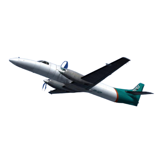
- Page 2 RAZAIR‐A1‐METRO‐III‐AFM‐001 Introduction Thank you for your purchase of RAZBAM’s Metroliner III SA227‐BC aircraft model. We at RAZBAM have worked to deliver to you the most accurate model of this fascinating aircraft and we promise you that you will enjoy flying it. The Fairchild Swearingen Metroliner or the Fairchild Aerospace Metro is a 19‐seat, pressurized, twin turboprop airliner first produced by Swearingen Aircraft and later by Fairchild The Metroliner was an evolution of the Swearingen Merlin turboprop‐powered business aircraft. Ed Swearingen, a Texas fixed base operator (FBO), started the developments that led to the Metro through gradual modifications to the ...
-
Page 3: Table Of Contents
RAZAIR‐A1‐METRO‐III‐AFM‐001 TABLE OF CONTENTS Acknowledgments ................................ i Control Configuration .............................. ii Realism Configuration .............................. iii Switches Navigation .............................. iv Hiding Cockpit Elements .............................. v Aircraft Description ............................... vii SECTION 1: AIRCRAFT CONTROLS .......................... 1 ‐1 1. Instrument Panels ............................ 1 ‐2 2. Flight Instruments ............................ 1 ‐5 3. Flight Control & Trim ............................ 1 ‐8 4. Electrical Power System .......................... 1 ‐10 5. - Page 4 RAZAIR‐A1‐METRO‐III‐AFM‐001 d. Before Takeoff ............................ 4 ‐4 e. Takeoff (Dry) ............................. 4 ‐4 Takeoff (With CAWI) .......................... 4 ‐5 g. Climb ................................. 4 ‐5 h. Cruise ................................ 4 ‐5 Descent .............................. 4 ‐6 Before Landing ............................ 4 ‐6 k. Balked Landing ............................ 4 ‐6 Landing .............................. ...
-
Page 5: Acknowledgments
RAZAIR‐A1‐METRO‐III‐AFM‐001 ACKNOWLEDGMENTS We wish to thanks all the people who were part of the RAZBAM Metroliner team. Ronald Zambrano ........................ Team Lead. Tim Taylor (Metal 2 Mesh) .................... 3D Modeler. José Valdez .......................... 3D Modeler. Hank Essers ........................... Texturizer. Larry Zambrano ........................ Gauge Coder. Bernt Stolle.......................... FDE Developer. Aaron Swindle(Sky Song Soundworks) .................. Sound Developer. Adam T. .......................... Researcher. Dan M. ........................... Researcher. Lorenz B. .......................... Researcher and Tester. i ... -
Page 6: Control Configuration
RAZAIR‐A1‐METRO‐III‐AFM‐001 CONTROL CONFIGURATION No special control configuration is required to fly this aircraft. REALISM CONFIGURATION The RAZBAM Metroliner has three unique realism settings: 1. Start Locks 2. Engine malfunction due to overtemp conditions. 3. Engine malfunction due to overtorque conditions. These realism settings can be enabled/disabled by the user as follows: 1. Go to the RAZBAM_MetroIIIC folder in the Gauges folder of your FSX/Prepar3D installation. 2. Select the RM3_RSET.xml file 3. Edit the file using a text editor like NotePad. 4. To enable a realism setting change the value to 1. To disable it, change it to 0. 5. The values to edit are: a. Start Locks = RM3_START_LOCKS b. Overtemp = RM3_ENG_OVERTEMP_FAIL c. Overtorque = RM3_ENG_OVERTORQUE_FAIL 6. Leave any other value unchanged. 7. Save the file and start the sim. These are the default realism settings: 1. Start Locks: Disabled. 2. Overtemp: Enabled. ... -
Page 7: Switches Navigation
RAZAIR‐A1‐METRO‐III‐AFM‐001 SWITCHES NAVIGATION TheMetroliner’s cockpit instruments have several types of switches, pushbuttons, knobs and levers. Usually you only have to click with your left mouse‐button on the switch to have it change its position, but there are several that have multiple positions that move back and forth. For these multiple position switches and knobs you have to left‐click to go forward and right‐click to go backwards. The following is a chart of the different switches and knobs found on the cockpit and how to navigate them. Switch Type Navigation 2‐Position Switch Left‐Click changes the position. 3‐Position Switch Left Click moves forward. Right Click moves backwards. Example: Left Click: ALTER‐AUTO‐DP PRIM. Right Click: DP PRIM‐AUTO‐ALTER. Multi‐position Knob Left Click moves forward. Right Click moves backwards. In some knobs, clicking on the center wheel will move them forward and backwards as well. ... -
Page 8: Hiding Cockpit Elements
RAZAIR‐A1‐METRO‐III‐AFM‐001 HIDING COCKPIT ELEMENTS In many occasions, access and visibility of certain cockpit instruments and/or switches, is impeded by other elements like the control yokes and levers. To allow for an easier access to these elements we have implemented a visibility control for the obstructing objects. CONTROL YOKES In normal conditions, the placement of the control yokes hinder access to the switches panel that are located just behind ... - Page 9 RAZAIR‐A1‐METRO‐III‐AFM‐001 THROTTLES The position of the throttle levers obstructs the vision of several gauges located behind them. This impairment works for both the pilot and copilot positions. There is a visibility control hot‐spot that will hide the throttle levers while the left mouse button is pressed. The throttles will automatically become visible as soon as the button is released. SPEED LEVERS The speed levers position prevents access to the engine SYNCROPHASER Switch and makes more difficult reading certain gauges. Like the throttle levers, there is a visibility control hot‐spot that will hide/reveal these levers. Unlike the throttle hot‐spot, the levers will remain hidden until you either click on the hot‐spot again or on the syncrophaser switch. No. 1 Hot spot hide the throttle levers while the mouse button is pressed. No. 2 Hot spot toggles the speed levers visibility. v ...
- Page 10 RAZAIR‐A1‐METRO‐III‐AFM‐001 COCKPIT CURTAIN The curtain that separates the cockpit from the passenger/cargo deck can be hid/shown by clicking on the following elements: By clicking on the curtain itself. By clicking on the fire extinguisher. By clicking on the no smoking/seatbelt sign. vi ...
-
Page 11: Aircraft Description
RAZAIR‐A1‐METRO‐III‐AFM‐001 AIRCRAFT DESCRIPTION The Metroliner III SA227‐BC is a pressurized twin turboprop airplane built by Swearingen Aircraft and later by Fairchild. The aircraft is powered by two Garrett AiResearch, now Honeywell, TPE‐331 turboprops with continuous alcohol‐water injection (AWI). Each engine uses a four‐bladed McCauley 4HFR34C652 or Dowty Rotol propeller. GENERAL CHARACTERISTICS Capacity Dimensions Performance Crew 2 Length 59 ft 4 in Max take‐off weight 16,000 lb Passengers 19 Height 16 ft 8 in Max Altitude 31,000 ft Cargo Volume 143.5 sq ft Wingspan 57 ft Max Speed 246 knots Max weight 8,700 lb Wing area 310 sq ft Range 1,150 nm vii ... -
Page 12: Section 1: Aircraft Controls
RAZAIR‐A1‐METRO‐III‐AFM‐001 AIRCRAFT CONTROLS 1‐1 ... -
Page 13: Instrument Panels
RAZAIR‐A1‐METRO‐III‐AFM‐001 INSTRUMENT PANELS Fig. 1 Main Instrument Panel 1. Pilot’s EHSI. 8. Flight Control Gauges: 2. Pilot’s EHSI Control Panel. a. Outside Air Temperature. 3. Copilot´s EHSI. b. Elevator Trim Position Indicator. 4. Copilot´s EHSI Control Panel. c. Flaps Position Indicator. 5. Pilot’s Flight Instruments: d. Hydraulic Pressure. a. Airspeed Indicator. e. Landing Gear Position Indicator. b. Attitude Indicator. 9. Left Hand Communication Panel: c. Pressure Altimeter. a. VHF 1 d. Vertical Speed Indicator b. NAV 1 e. - Page 14 RAZAIR‐A1‐METRO‐III‐AFM‐001 Fig. 2 Lateral Panels Left Hand Panel Right Hand Panel 1. Miscellaneous Controls: 4. Miscellaneous Controls: a. Temp Test. a. Cargo Door Control Panel. b. SRL Switches. b. Copilot Flight Instruments Light Knob. c. Pilot Flight Instruments Light Knob. 5. Right Essential Buss Breaker Panel. d. Electric Power Usage Indicators. 6. Non‐ Essential Buss Control Switch. e. AC Bus Voltmeter. 7. Non‐Essential Buss Breaker Panel. DC Bus Ammeter. 8. Right Hand Bus Transfer Switches. g. Nose Gear Steering System Panel. h. Engine Start System Panel. Cabin Pressurization Controls. 2. Left Essential Buss Breaker Panel 3.
- Page 15 RAZAIR‐A1‐METRO‐III‐AFM‐001 Fig. 3 Center Console 1. Left & Right Boost Pumps Switches 14. Cockpit Light Switches: 2. Stop & Feather Switches. a. Glareshield Lights. (Accessible from the 3. Engine Throttle levers. pilot position) 4. Speed Levers. b. Console Backlight. 5. Flaps Lever. c. Center Instruments (Accessible from the 6. AWI Control Panel: copilot position) a. AWI On/Off Switch 15. Propeller Synchrophaser Switch. b. AWI Pump Selector/Test Switch. 16. Gust Lock Lever. 7. Left & Right Fuel Cutoff Switches 17. Throttle Friction Lock Lever. 8. Left 6 Right Hydraulic Fluid Cutoff Switches 18. Speed Friction Lock Lever. 9.
-
Page 16: Flight Instruments
RAZAIR‐A1‐METRO‐III‐AFM‐001 FLIGHT INSTRUMENTS There are two sets of flight instruments for both the Pilot and the Copilot. They both work with the Static Pressure and are not subject to failure in the event of losing electric power. If the alternate static pressure source is selected, the Copilot’s flight instruments become inoperational. Airspeed Indicator: The airspeed indicator displays the aircraft speed in Knots. It has the following elements: 1. A plain needle that indicates current aircraft speed. 2. A stripped needle that indicates maximum airspeed based on aircraft altitude. 3. Three thumb indicators that rotate to display: White: Minimum speed for aircraft control. b. Yellow: Minimum speed for safe climbing. Blue: Maximum speed for landing gear operation. The maximum operational speed up to 17,800 feet is 246 Knots. Above that altitude the maximum operational speed will be the following: Altitude Knots 18,000 245 20,000 235 23,000 221 Fig. 4 Airspeed Indicator 26,000 208 ... - Page 17 RAZAIR‐A1‐METRO‐III‐AFM‐001 Fig. 8 Radar Altimeter (Pilot Only) Fig. 7 Vertical Speed Indicator (feet/minute) . RADAR ALTIMETER Among the instruments available to the pilot you can find the radar altimeter. 1. Below minimum AGL altitude warning light. 2. OFF flag (hidden). 3. Minimum AGL altitude indicator. 4. Minimum AGL altitude selector knob. 5. AGL altitude indicator. Operation The radar altimeter is ON whenever there is power available to the Pilot’s Instruments Panel. It indicates altitude above ground level (AGL) from 0 up to 2.500 feet. The OFF flag appears in two occasions: a) When the aircraft AGL altitude exceeds 2,500 feet; and b) when the radar altimeter has no power. ...
- Page 18 RAZAIR‐A1‐METRO‐III‐AFM‐001 STALL AVOIDANCE SYSTEM (SAS) The Metroliner III is equipped with a stall avoidance system (SAS) which is armed at liftoff and disarmed as speed increases. Fig. 11 SAS Test Overhead Panel. Fig. 10 SAS Gauge. Fig. 12 SAS ON/OFF Switches Fig. 13 SAS Servo Switch 1‐7 ...
- Page 19 RAZAIR‐A1‐METRO‐III‐AFM‐001 The SAS provides a visual warning when the aircraft airspeed is insufficient and it is about to enter into a stall condition. The SAS System must be in operation for flight. There are two SAS sensors, one for each pitot tube vane,and yellow SAS L and SAS R lights will illuminate when they are enabled for operation. The SAS system operates at airspeeds below 140 KIAS, the SAS L & SAS R lights will illuminate indicating that the system is armed. At above 140 KIAS the lights turn off indicating that the system is enabled but not operational. During operation, the gauge needle will approach the red zone as the airspeed decreases and the aircraft approaches a stall condition. The system is operational when the SAS SERVO switch and the SAS L and SAS R are all in their ON position. If the SAS SERVO switch is in the OFF position (default) a SAS SERVO light will illuminate in the annunciator panel. SAS L FAIL and SAS R FAIL yellow lights will illuminate if either SAS L or SAS R switch is in the OFF position. Under low ambient temperature conditions place the PITOT HEAT L and R switches in the PITOT & SAS HEAT position to prevent icing in the SAS vanes. A green SAS DEICE light will illuminate indicating that SAS heat has been selected. NOTE The SAS indicator is not certified for use as an in‐flight approach ...
- Page 20 RAZAIR‐A1‐METRO‐III‐AFM‐001 Fig. 16 Trim Controls and Indicators Location. Fig. 15 Trim Controls. AILERON (ROLL) TRIM The trim tab of each aileron is connected to the AILERON TRIM wheel (Fig 15‐3) on the pedestal. Left or right clicking on the trim wheel positions both tabs for lateral trim. As the outer wheel rotates, the inner wheel rotates in the same direction at a reduced rate. The aileron trim tabs are in the neutral position when the index lines on both the outer and inner wheels are aligned vertically. RUDDER (YAW) TRIM The rudder trim tab is actuated by the RUDDER TRIM wheel (Fig 15‐2) on the pedestal. Left or right clicking n the trim wheel positions the tab for yaw trim. ELEVATOR (PITCH) TRIM There are no trim tabs on the elevators; pitch trim is accomplished by moving the entire horizontal stabilizer. ...
-
Page 21: Electrical Power System
RAZAIR‐A1‐METRO‐III‐AFM‐001 Fig. 19 FLAP POSition Fig. 20 FLAP POSition indicator location. indicator. Fig. 18 FLAP lever. ELECTRICAL POWER SYSTEM The electrical power system provides 28 volt DC, 115 volt AC and 26 volt AC power for all airplane electrical requirements. An external power source, engine‐driven starter‐generators, and nickel‐cadmium batteries supply the DC power. AC power is provided by two static inverters. DC and AC power are distributed through two independent bus systems. ... - Page 22 RAZAIR‐A1‐METRO‐III‐AFM‐001 Battery voltage may be monitored by selecting the appropriate voltmeter switch position. The voltmeter and selector switch are located on the pilot´s side console (Fig 22). Fig. 22 Voltage selector and meter. The temperature of the batteries is monitored by an indicator and two switches (fig 23). The indicator contains a temperature meter for each battery (fig 23‐5), an amber WARM light (fig 23‐4), which illuminates if either battery temperature exceeds 120ºF, and a red HOT light (fig 23‐3) which illuminates if either battery exceeds 150ºF. ...
- Page 23 RAZAIR‐A1‐METRO‐III‐AFM‐001 AC POWER AC electrical power is supplied by single‐phase inverters. Two inverters are installed but only one is used at a time. The inverter selector switch position determines which one is used. The inverters produce 115 volt and 26 volt AC power. Fig. 25 AC power voltmeter. The AC warning and monitoring system includes a bus selectable voltmeter on the left console (Fig 25) and two bus failure warning lights on the annunciator panel. The AC voltmeter can be selected to monitor either the left or the right 115 volt bus. If power to either 115 volt bus is lost, the respective AC BUS warning light illuminates. Illumination of both warning lights is usually an indication of inverter failure and the other inverter should be selected. POWER DISTRIBUTION Aircraft power is distributed through three DC and four AC busses. DC power is distributed through the Left Essential Bus (LEB), the Right Essential Bus (REB) and the Non‐Essential Bus (NEB). Both the LEB and RB are limited to 225 amperes while the NEB is limited to 150 amperes. The LEB is located in the left console. The REB and NEB are located in the right console. Each bus is connected to the distribution system with the bus tie switch mounted on the respective console (Figures 26 and 27). ...
-
Page 24: Master Warning System
RAZAIR‐A1‐METRO‐III‐AFM‐001 Fig. 27 Right Essential Bus Transfer switches. Fig. 26 Left Essential Bus Transfer switches Additionally either the LEB or REB provides power to the inverters to produce AC power. DC electrical power for control and operation of the No. 1 inverter is supplied by the LEB. The REB supplies the No. 2 inverter. The No. 1 inverter supplies power to the left 115‐VAC and left 26‐VAC busses while the No. 2 inverter supplies the right 115‐VAC and right26‐VAC busses. The 115‐VAC busses re connected through a circuit breaker as well as the 26‐ VAC busses. Consequently either inverter provides power to all four AC busses. NOTE Many of the aircraft’s gauges and instruments depend on electrical power. If one of them is not working check the electrical power switches to and meters for any power problem. MASTER WARNING SYSTEM The master warning system consists of an annunciator panel, a valve position annunciator panel and various other lights. Most lights are located on the annunciator panel. An illuminated light alerts the pilot to a system malfunction (red), a system operating parameter (amber), or a system normal operating condition (green). When a light illuminates, the pilot should follow the approved checklist procedure. Fig. 28 Annunciator Panel. 1‐13 ... - Page 25 RAZAIR‐A1‐METRO‐III‐AFM‐001 Fig. 29 Valve annunciator panel. Fig. 30 Fire extinguisher annunciators ANNUNCIATOR PANEL The annunciator panel (Fig 28) contains red warning lights to advise the pilot of serious system conditions, amber cautionlights to indicate conditions of a less serious nature, and green lights to indicate other specific system conditions. A PRESS TO TEST switch is located on the left side of the panel. Clicking on the switch will check all the warning system lights. ANNUNCIATOR REASON FOR ILLUMINATION Illuminates only during test. L ENG FIRE Excessive temperature is detected in associated engine nacelle ...
- Page 26 RAZAIR‐A1‐METRO‐III‐AFM‐001 ANNUNCIATOR REASON FOR ILLUMINATION command reverse operation. R BETA LOW SUCTION Insufficient suction for vacuum system. L CHIP DET Metal particles detected in the engine oil. (Illuminates only during test). R CHIP DET L XFER PUMP Fuel lever in hopper tank is low (Fuel boost pumps are off). R XFER PUMP A GPU plug is plugged into the external power GPU PLUG IN receptacle. ...
- Page 27 RAZAIR‐A1‐METRO‐III‐AFM‐001 ANNUNCIATOR REASON FOR ILLUMINATION L FUEL FILTER The indicated fuel filter is being bypassed. (Illuminates only during test). R FUEL FILTER L INTAKE HT If the intake heat switch is on, the engine anti‐ ice valve is open. If the TEST switch is clicked, R INTAKE HT the valve is closed. L W/S HT Indicated windshield heat is active. R W/S HT AWI PUMP Nº1 The indicated AWI pump is operating. AWI PUMP Nº2 NWS Nose Wheel Steering system is active. ...
- Page 28 RAZAIR‐A1‐METRO‐III‐AFM‐001 FIRE EXTINGUISHER ANNUNCIATORS The annunciators for the fire system re located on the instrument panel (Fig. 30). Each is part of a three‐lens control switch light. The FIRE portion of the annunciator may be tested with the PRESS TO TEST switch or with the FIRE EXT TEST switch located between the lights. ANNUNCIATOR REASON FOR ILLUMINATION 1. Excessive temperature in the engine FIRE nacelle. 2. The annunciator PRESS TO TEST switch is E OK actuated. 3.
- Page 29 RAZAIR‐A1‐METRO‐III‐AFM‐001 DOOR UNSAFE The cargo door is not closed or safe. The door handle is in the open position and the click‐clack warning switches are operating SWTICHES correctly. NORMAL 1‐18 ...
-
Page 30: Engine Instruments And Control
RAZAIR‐A1‐METRO‐III‐AFM‐001 ENGINE INSTRUMENTS AND CONTROLS The Metro III is powered by two turboprop engines driving four‐blade constant speed propellers. The propellers include full‐feathering and reversing capabilities. The engines are lightweight, fixed‐shaft turboprops manufactured by Honeywell, previously Garret AiResearch, and are designated TPE‐331. The engines incorporate a factory‐installed alcohol‐water injection system (AWI). The TPE‐331 is dry‐rated at 1,000 shp for takeoff and continuous operation. It is wet‐rated at 1,100 shp for a maximum of five minutes from the start of takeoff roll. Fig. 31 Engine Stations, Major Sections and Fuel Flow The engine systems include the following: Instrumentation. SRL Autostart computer. Oil system. ... - Page 31 RAZAIR‐A1‐METRO‐III‐AFM‐001 ENGINE INSTRUMENTS The engine instruments (Figure 32) are located in two vertical rows on the center instrument panel. From top to bottom, the gauges are: Exhaust gas temperature (EGT): marked in degrees Celsius. Engine Starter Warning Light: Indicates when the engine ignition system is active. Fuel Bypass Open Warning Light: indicates when the SRL computer activates the fuel bypass to maintain engine temperature at safe levels. ...
- Page 32 RAZAIR‐A1‐METRO‐III‐AFM‐001 Fig. 34 Propeller Torque % Fig. 33 Exhaust Gas Temperature ATTENTION: Torque increases at lower Propeller Speeds. ATTENTION: Maximum Operational EGT is 650 C. Fig. 36 Engine Fuel Flow Fig. 35 Engine RPM % Fig. 38 Fuel Quantity Fig. 37 Engine Oil Pressure and Temperature 1‐21 ...
- Page 33 RAZAIR‐A1‐METRO‐III‐AFM‐001 Fig. 40 Engine Ignition Light Fig. 41 Engine Fuel Bypass Warning Light Fig. 39 Fuel Pressure SINGLE RED LINE (SRL) AUTOSTART COMPUTER The SRL autostart computer controls three functions: engine speed switching functions, automatic start fuel enrichment and single red line EGT computation. The speed switching functions of the SRL include: 1. Automatic control of the start sequence from 10% to 60% rpm, 2. SRL EGT computation above 80% rpm, and 3. Enabling CAWI operation and EGT temperature limiting above 90% rpm. The automatic start fuel enrichment modulates the start fuel enrichment valve to provide an appropriate amount of fuel during the start. The SRL EGT computation results in an indicated EGT with a single maximum EGT of 650 C for all operations. Fig. 42 SRL Control Panel. Fig. 43 SRL Control Panel Location. 1‐22 ...
-
Page 34: Fuel System
RAZAIR‐A1‐METRO‐III‐AFM‐001 OIL SYSTEM The engine oil system provides for cooling and lubrication of the main engine bearings and the reduction gear. In addition to these functions the engine oil system supplies oil for propeller control, negative torque sensing (NTS) and the unfeathering pump. If oil pressure drops below 40 PSI the appropriate L or R OIL PRESSURE warning light in the annunciator panel will illuminate. ... - Page 35 RAZAIR‐A1‐METRO‐III‐AFM‐001 Fig. 44 Engine START and STOP Buttons. Fig. 45 ENGINE STOP AND FEATHER Controls. ENGINE TEMPERATURE MONITORING SYSTEM An EGT gauge is provided for each engine for engine temperature monitoring (Figure 33). Below 80% rpm, compensated EGT is displayed on the EGT indicators. Above 80% rpm, a computed EGT is displayed. Below 80% rpm, the engine temperature signal proceeds to the EGT gauge without modification. Above 80% rpm, the engine temperature signal is sent to the SRL for compensation. The computed EGT shows the pilot how close the engine is to the maximum allowable. The maximum permissible computed EGT is 650 C for all operations except starting. Display of EGT values for below 80% rpm and computed EGT values for operations above 80% rpm is controlled automatically by the SRL‐Autostart computer. Two SRL ΔP/P switches (Figure 42) are provided for SRL activation. Amber lights marked “L SRL OFF” and “R SRL OFF”, located on the annunciator panel, advise the pilot when raw EGT is displayed on the EGT gauge or when the SRL computer is OFF. The SRL OFF light is normally illuminated below 805 rpm; if a SRL OFF light is illuminated when rpm is over 80% a malfunction is indicated. TEMPERATURE LIMITER SYSTEM The system consists of a temperature limiter and a fuel bypass valve. The system functions automatically to limit EGT to C by opening the fuel bypass valve and bypassing metered fuel back to the fuel pump. The temperature limiter is integrated with the SRL computer. It is armed whenever the SRL switch is in the NORM (center) position and rpm is above 90%. The system prevents EGT from exceeding the SRL value of 650 C. ...
- Page 36 RAZAIR‐A1‐METRO‐III‐AFM‐001 WARNING Do not test the temperature limiter in flight. Engine flameout will result. ENGINE TORQUE MONITORING SYSTEM The torque‐measuring system monitors the twisting force being applied to the propeller through the reduction gear. The signal is sent to the torque indicator (Figure 34) in the cockpit. IGNITION SYSTEM The ignition system is a high‐energy type consisted of an engine‐mounted ignition exciter and two igniter plugs located in the combustion chamber. An independent ignition system is provided for each engine. Ignition operation is indicated by amber lights located below the EGT gauges (Figure 40). The associated light is on whenever power is applied to the ignition exciter. Fig. 47 Ignition System Switches Location. Fig. 46 Ignition System Switches The ignition system is controlled by two switches on the left console labeled AUTO/CONT IGNITION. The AUTO position (default position) allows the SRL‐Autostart computer to control ignition during start. An additional feature of the AUTO position is that it energizes the ignition if the negative torque sensing (NTS) system is activated. Engine failure or flameout permits the propeller to drive the engine (negative torque), causing the ignition to be energized as long as the ...
- Page 37 RAZAIR‐A1‐METRO‐III‐AFM‐001 PROPELLERS Each engine drives a four‐blade, constant‐speed propeller. The propellers incorporate full feather and reverse capabilities, in addition to Beta mode control for ground operation. Propeller start locks are provided to maintain minimum blade angle to reduce propeller drag during engine start. The propellers are normally controlled by the interaction of the power (throttle) levers, speed levers and the propellers STOP AND FEATHER controls, which are used only under abnormal or emergency conditions. A propeller is onspeed when the actual rpm equals the selected rpm. Underspeed exists when the actual rpm is less than the selected rpm. Overspeed exists when the actual rpm is greater than the selected rpm. In turboprop engines, rpm is a sole function of blade angle; and in flight at a constant power setting, blade angle is a sole function of true airspeed. A constant‐speed propeller makes changes to the blade angle based on airspeed, altitude, temperature, power lever and speed lever position to maintain a selected rpm. ...
- Page 38 RAZAIR‐A1‐METRO‐III‐AFM‐001 The propeller start locks consist of two spring‐loaded pins that engage the propeller piston and, consequently, lock the blades in a flat pitch position. The start locks remain engaged following engine start because of the shear loads applied to the pins by the propeller piston. The start locks are released when ready to taxi by selecting REVERSE with the power lever to remove shear loads. During a normal shutdown, the STOP button is first pushed to shut off fuel; then the power lever is moved into REVERSE as the rpm decays below 50%. As the propeller decelerates the start locks re‐engage. After the rpm decays below 10% the power levers can be released. NEGATIVE TORQUE SENSING (NTS) SYSTEM Negative torque occurs when the propeller drives the engine, as opposed to the positive torque developed when the engine is driving the propeller. Loss of engine power during flight results in loss of positive torque, and the windmilling propeller produces negative torque, which results in drag that decreases performance and increases yaw. The engine has a negative torque‐sensing (NTS) system that provides for automatic drag reduction without any action on the pilot’s part. It is NOT an autofeather system, but rather a system that increases blade angle to reduce windmilling drag. The pilot must still feather the propeller. SYNCHROPHASING After takeoff and when climb power is established, a propeller synchrophaser can be used to synchronize the propeller rpm and establish a blade phase relationship, called synchrophasing. Combining synchronizing and synchrophasing help reduce propeller noise and result in greater passenger comfort. The system operates to match the rpm of the slow engine to that of the fast engine over a very limited range. It is recommended that the engines be manually synchronized before turning the system on. ...
- Page 39 RAZAIR‐A1‐METRO‐III‐AFM‐001 Fig. 49 Powerplant Control: 1) Power levers; 2) Speed levers. POWER (THROTTLE) LEVER Two power levers operate in a quadrant on the center pedestal which is marked “FLT IDLE”, “GROUND IDLE,” and “REVERSE.” The power lever connects to the propeller pitch control and the fuel control unit. When the power lever is between FLT IDLE and REVERSE, any movement positions the propeller pitch control to provide a blade angle proportional to the power required. When the power levers is positioned forward of the FLT IDLE, propeller pitch control is provided by the speed levers. The power lever can move freely between HIGH (full forward) ...
- Page 40 RAZAIR‐A1‐METRO‐III‐AFM‐001 CONDITION LEVERS The powerplant does not have user controlled condition levers. They are coupled with the speed levers. Their position changes with the speed levers position. The condition levers are actuated automatically as long as the SRL computer is active; otherwise they are locked at their lowest value. WARNING Engine torque tends to increase when the speed levers are at low rpm. An overtorque condition will appear if the power levers are at HIGH while the speed levers are at LOW. Reduce power to keep the torque within safe limits. IF THE OVERTORQUE CONDITION REMAINS FOR TOO LONG THE ENGINE WILL CATCH FIRE . STOP AND FEATHER CONTROL ...
- Page 41 RAZAIR‐A1‐METRO‐III‐AFM‐001 NOTE The only way to put the power (throttle) levers below FLT IDLE is by using the keyboard. FSX/P3D limits the movement of the throttle to 0% in the cockpit. Reverse thrust is only achieved by going below 0 % into negative throttle values. CAUTION Attempted reverse with the speed levers below the HIGH rpm position may result in engine overtemperature condition. ENGINE START Starts may be automatic or manual. AUTOMATIC GROUND START 1. Set the speed lever at low and the power lever at FLT IDLE (10% throttle). 2.
- Page 42 RAZAIR‐A1‐METRO‐III‐AFM‐001 Fig. 50 START MODE Switch Fig. 51 START MODE Switch location MANUAL GROUND START If no fuel flow or ignition is observed at 10% rpm, and there is no EGT rise, it is possible that the automatic start sequence failed. In this case, it is permissible to attempt a manual start as described in the Abnormal Procedures Section. ...
- Page 43 RAZAIR‐A1‐METRO‐III‐AFM‐001 NOTE After an aborted start it is possible that when attempting a new start the engine ignition system gets stuck at 100% rpm. To clear it click on the START button again. AIRSTARTS Airstarts are the same as ground starts except for power lever and speed lever positions. 1. Power lever is placed at 15% throttle. 2. Speed lever is placed at 97% propeller governor rpm. ATTENTION For ground starts and in order to prevent accidental power surges, the ignition system will not engage if the power lever is above 12% throttle. Engines will not start either in the ground or in the air if the power levers are in reverse. ENGINE SHUTDOWN NORMAL SHUTDOWN To accomplish a normal shutdown, click on the engine STOP button (Fig 22). The fuel valve will close and engine rpm will decay. PREPLANNED SHUTDOWN IN FLIGHT To ...
- Page 44 RAZAIR‐A1‐METRO‐III‐AFM‐001 Fig. 55 AWI fluid quanitity gauge location. Fig. 54 AWI fluid quantity gauge. CONTROL The CAWI system is controlled by: a) a two‐position WATER INJECTION switch with positions marked “CONT” and “OFF” located on the center pedestal and b) a three‐position switch labeled AWI PUMP TEST. It has two marked positions “No. 1” and “No. 2,” and an unmarked center OFF position (fig. 56). Fig. 57 CAWI control switches location. Fig. 56 CAWI Control switches INDICATION Two annunciator lights marked “AWI No. 1 PUMP ON” and “AWI No. 2 PUMP ON” are illuminated whenever the associated AWI pump is running ad developing acceptable pressure. If the WATER INJECTION switch is OFF, holding the AWI PUMP TEST switch to the No 1 or No 2 position should turn on the associated AWI light. OPERATION To activate the CAWI system for takeoff: 1.
- Page 45 RAZAIR‐A1‐METRO‐III‐AFM‐001 3. The WATER INJECTION switch must be placed in CONT. 4. The AWI PUMP TEST switch is placed in either the No 1 or No 2 position. When these conditions are met, the AWI fluid will flow into the engines. An immediate torque increase between 30% to 35% will be noticed and the selected AWI PUMP ON light will illuminate. AWI fluid flows continuously until the WATER INJECTION is clicked to the OFF position, the AWI PUMP TEST switch is placed in the OFF position, the AWI fluid runs out or engine rpm decreases below 90% rpm. AWI flow is independent for each engine, so if the flow shuts for one engine it will continue for the other one while the operating conditions are met. NOTE When the AWI fluid stops, engine torque will drop by as much as 35%. FUEL SYSTEM The fuel system consists of the fuel storage and vent, fuel transfer and engine feed, and indicating systems. The total usable fuel capacity is 4,342 pounds (648 US gallons at 6.7 pounds per gallon). FUEL STORAGE The fuel storage consists of two integral wet‐wing tanks and a vent system (Fig 58). Fig. 58 Fuel Storage tanks. FUEL TRANSFER AND ENGINE FEED SYSTEM Fuel to each engine is supplied by an independent fuel system from its respective wing tank. A crossflow line interconnects the left and right wing tanks. Each fuel tank has two submerged boost pumps. ...
- Page 46 RAZAIR‐A1‐METRO‐III‐AFM‐001 Fig. 59 Fuel Boost Pump and Shutoff Valve controls Fig. 60 Fuel Boost Pump/Shutoff Valve controls Location. CROSSFLOW SYSTEM A crossflow line interconnects the left and right wing tanks and incorporates a crossflow valve for fuel balancing from one wing tank to the other. The crossflow valve is controlled by the CROSSFLOW SWITCH, a rotary siwthc located on the pilot and copilot’s switch panel. Fig. 61 Fuel crossflow switches The X‐FLOW OPEN light on the valve position annunciator panel illuminates when the valve is partially or fully open. FUEL SHUTOFF VALVE SYSTEM Each engine has a fuel shutoff valve in the wheel well that is controlled by the FUEL SHUTOFF switch on the center console (Fig. 59). These normally open valves allow fuel to pass to the engines. The amber L or R FUEL shutoff valve light illuminates when the respective valve is closed. FUEL QUANTITY INDICATOR The FUEL QTY gauge (Fig. 38) on the instrument panel is calibrated in pounds x 100. This gauge is equipped with two pointers, one for each wing tank. The gauge is tested by clicking on the PRESS TO TEST push‐button switch adjacent to it. ...
-
Page 47: Fire Protection System
RAZAIR‐A1‐METRO‐III‐AFM‐001 FUEL CONSUMED TOTALIZER The fuel‐consumed totalizer indicates the total amount of fuel consumed by both engines since the counter was last zeroed. Zeroing is accomplished by clicking on the mechanical reset lever on the totalizer. NOTE The fuel consumed totalizer is automatically zeroed when an engine is started. Fig. 62 Fuel Consumed Totalizer FIRE PROTECTION SYSTEM The fire protection system consists of engine overheat detection systems and engine fire‐extinguishing systems. There are cockpit warning lights located on the annunciator panel and on the fire extinguisher control assembly (Fig 63). Heat sensors and a fire extinguisher, which is discharged from the cockpit, are located within each engine nacelle. Fig. 63 Fire Extinguisher Control Panel ENGINE FIRE DETECTION Each engine has a simulated fire detector, when a fire condition in an engine is detected the red FIRE warning light illuminates in both the annunciator panel and in the fire extinguisher control panel. The FIRE light turns off when the fire ... -
Page 48: Pneumatic System
RAZAIR‐A1‐METRO‐III‐AFM‐001 PNEUMATIC SYSTEMS The pneumatic system provides the bleed air manifold with hot compressed air for use by associated systems. The pneumatic system consists of a bleed air system and vacuum system. Both engines provide air to the manifold, but either engine is sufficient to maintain all required system functions during single engine operation. BLEED AIR SYSTEM ... -
Page 49: Landing Gear
RAZAIR‐A1‐METRO‐III‐AFM‐001 LANDING GEAR The airplane has a dual‐wheel, retractable, tricycle landing gear enclosed by mechanically actuated doors. Gear position and warning are provided by indicator lights and a warning horn. The nosewheel steering system provides directional control while taxiing. The nosewheel casters freely when the system is not engaged. The standard braking system is manual. LANDING GEAR The landing gear is controlled by the LANDING GEAR LEVER located in the center console. Clicking on the lever will rise or lower the landing gear. The LDG POS indicator will display landing gear position. Fig. 65 Landing Gear Lever Fig. 66 LDG POS indicator (test). Fig. 67 LDG POS indicator (transition). Fig. 68 LDG POS indicator (gear down). Green lights indicate that the landing gear is down and locked. Red lights indicate that the landing gear is in transition and no lights indicate that the landing gear is in the up and stowed position. 1‐38 ... -
Page 50: Icing System
RAZAIR‐A1‐METRO‐III‐AFM‐001 DEICING SYSTEM Ice protection is provided for the following components. Wings and horizontal stabilizer. Engines and nacelle inlets. Propellers Pitot tubes and SAS vanes. Fig. 69 Deicing switches. The leading edges of the wing and horizontal stabilizer are protected by electrically controlled and pneumatically operated deice boots. To activate the system click the DEICE BOOTS switch to the AUTO position. The engine inlets are heated by hot bleed air tapped from the engine. The propellers, pitot tubes and SAS vanes are electrically operated. The deicing system switch board is located in the left hand instruments panel. LIGHTING SYSTEM EXTERIOR LIGHTS Exterior lighting consists of navigation, rotating beacon, wing ice, landing, taxi, strobe logo and recognition lights. The exterior lighting system is equipped with: Five navigation lights: two red on the left wingtip, two green on the right wingtip, and one clear in the tail cone. ... - Page 51 RAZAIR‐A1‐METRO‐III‐AFM‐001 Two recognition lights located under a cover on the leading edge of each wing. Three strobe lights, one on each wingtip and one on the tail. One red rotating beacon mounted on top of the vertical stabilizer. Two logo lights, one on the top of each horizontal stabilizer. One taxi light located on the nose landing gear. Fig. 70 Exterior lights switch panel. INTERIOR LIGHTS Interior lighting consists of cockpit, cabin and emergency lighting. Lighting for the cockpit area consists of general illumination of the instrument panel, overhead floodlights, pilot and copilot instruments lights, engine and auxiliary instruments lights, map lights and console and pedestal lights. Pilot and copilot flight instrument lights are controlled by individual dimmers on the left and right forward consoles. Fig. 71 PIlot's Instruments lights control. Fig. 72 Copilot's instruments lights control. ...
- Page 52 RAZAIR‐A1‐METRO‐III‐AFM‐001 Fig. 73 Cockpit lights controls NOTE It is not possible to activate the exterior and interior lights by using the standard keyboard commands and/or external control boxes. Since the aircraft uses three‐position rocker switches instead of simple ON/OFF toggles, a special code was required that cannot be handled from outside the virtual cockpit. ...
-
Page 53: Section 2: Avionics
RAZAIR‐A1‐METRO‐III‐AFM‐001 AVIONICS 2‐1 ... -
Page 54: Communications And Navigation
RAZAIR‐A1‐METRO‐III‐AFM‐001 COMMUNICATIONS AND NAVIGATION The SA‐227‐BC Communications and navigation instruments consist of the following: Two VHF Receiver/Transmitters. Two NAV Receivers. One ATC Transponder. One ADF Receiver. One DME Receiver. Two Audio control panels. All the communications and navigations instruments, except for the DME receiver, are located on the upper portion of the main instruments panel divided in Left Hand and Right Hand sets. Fig. 74 Communications and Navigation instruments panel. The left hand panel is used by the pilot and contains the following instruments (from left to right): Audio control panel. VHF1 Receiver/Transmitter. NAV1 Receiver. ATC Transponder. The right hand panel is used by the copilot and contains the following instruments (from left to right): ADF1 Receiver. NAV2 Receiver. VHF2 Receiver/Transmitter. Audio control panel. The DME receiver is located in the center of the main instruments panel to the left of the weather radar display. 2‐2 ... - Page 55 RAZAIR‐A1‐METRO‐III‐AFM‐001 NOTE The communications and navigation instrument panel needs that both electrical power is available and that the Avionics Master Switch is in the ON position. VHF RECEIVER/TRANSMITTER The aircraft has two VHF receiver/transmitters. They are capable of receiving and transmitting in the FSX/Prepr3D assigned frequency range of 118.00 to 136.97 MHz, both units have an Active and a Standby frequency. The displays for the VHF receiver/transmitters are based on the Collins ...
- Page 56 RAZAIR‐A1‐METRO‐III‐AFM‐001 NOTE FSX/Prepar3D always enables COM1 (VHF1) for reception. It is not possible to deselect it. NAV RECEIVER The aircraft has two VHF receivers for NAV frequencies. They are capable of receiving in the FSX/Prepr3D assigned frequency range of 108.00 to 117.97 MHz, both untis have an Active and a Standby frequency. The displays for the NAV receivers are based on the Collins CTL‐32 Digital Display. ...
- Page 57 RAZAIR‐A1‐METRO‐III‐AFM‐001 The display for the ATC Transponder unit is based on the Collins CTL‐92 Digital Display. 1. Power/Volume knob. a. Outer knob: Power. b. Inner knob: Volume (INOP). 2. Code selector knob. 3. Code display. 4. Unit operational mode. OPERATION The unit is OFF by default, to turn it ON click on the OUTER Power/Volume knob. The display will appear and the unit will be ready for operation. To input a selected code you must click on both the Outer and Inner Code selector knob as follows: Outer knob: Left‐Click to change the 1000s number group. Right‐Click to change the 100s number group. Inner knob: Left‐Click to change the 10s number group. Right‐Click to change the 1s number group. Fig. 77 ATC Transponder display. ADF RECEIVER The aircraft has one ADF receiver. It is capable of receiving in the FSX/Prepr3D assigned frequency range of 100.0 to 1799.9 KHz. ...
- Page 58 RAZAIR‐A1‐METRO‐III‐AFM‐001 4. Radial to selected ADF station display. OPERATION The units are OFF by default, to turn them ON click on the OUTER Power/Volume knob. The display will appear and the unit will be ready for operation. To change a frequency click on the outer knob to change whole number values in the 100 to 1799 range. Clicking on the inner knob will change values in the 0.0 to 0.9 range. DME RECEIVER The aircraft has one DME receiver display. It is tied to the NAV receivers and can display DME information when available. 1. Power Switch 2. Display Mode Switch. 3. Channel Switch 4. Secondary Information Display 5. Secondary Information Label. 6.
- Page 59 RAZAIR‐A1‐METRO‐III‐AFM‐001 Fig. 80 Audio Control Panel The following functions are enabled: 1. AUDIO: a. VHF1: Enables audio reception for the VHF1 (COM1) receiver. b. VHF2: Enables audio reception for both VHF1 and VHF2 receivers. c. NAV1: Enables audio reception for the NAV1 IDENT Morse code. d. NAV2: Enables audio reception for the NAV2 IDENT Morse code. e. DME1: Enables audio reception for the DME IDENT Morse code. DME2: Enables audio reception for the DME IDENT Morse code. g. ADF1: Enables audio reception for the ADF1 IDENT Morse code. h. ADF2: Enables audio reception for the ADF2 IDENT Morse code. MKR: Enables audio reception for MARKER Beacons signals. 2. MICROPHONE: a. VHF1: Selects VHF1 for radio transmission. b. VHF2: Selects VHF2 for radio transmission. OPERATION All AUDIO functions, except for the VHF1 and VHF2 reception switches, work as a toggle. Clicking on it repeatedly selects/deselects the desired function. ...
-
Page 60: Ehsi - Electronic Horizontal Situation Indicator
RAZAIR‐A1‐METRO‐III‐AFM‐001 ATTENTION It is not possible to deselect the audio output for the VHF1 (COM1) radio. Clicking on VHF2 will enable audio output for BOTH radios. It is possible that you will hear another transmission on top of the one meant for you. EHSI – ELECTRONIC HORIZONTAL SITUATION INDICATOR The SA‐227‐BC comes from the factory with an EHSI installed. The EHSI is an Electronic Flight Instrument System (EFIS), it combines the function of a Horizontal Situation Indicator (HSI), RMI, GPS Moving Map and TCAS screen in a single device. Both the pilot and the copilot have their own individual EHSI. They can be configured independently but all navigation data is shared. Fig. 82 Copilot's EHSI Display and Control panel. Fig. 81 PIlot's EHSI Display and Control panel Fig. 84 EHSI Control panel. Fig. 83 EHSI Display The EHSI will display data from the following instruments: ... - Page 61 RAZAIR‐A1‐METRO‐III‐AFM‐001 NAV1 and NAV 2 receivers DME1 and DME2 GPS ADF1 Directional Gyro TCAS EHSI DISPLAY The EHSI has three display areas: The primary display area, the upper display area and the bottom display area. Fig. 85 EHSI Display 2‐9 ...
- Page 62 RAZAIR‐A1‐METRO‐III‐AFM‐001 A. Upper display area. B. Primary display area. C. Bottom display area. 1. Primary NAV bearing pointer. 2. Aircraft current magnetic heading. 3. Compass card. 4. Selected heading cue. 5. ADF1 bearing pointer. 6. Course pointer. 7. Secondary NAV bearing pointer. 8. Aircraft position. PRIMARY DISPLAY AREA The primary display area shows either a 360 degree or a 120 degree ARC view, as indicated by the white compass ring. The white airplane represents the aircraft’s current position. The primary display area also depict current GPS flight plan, airports, navaids, airspaces, intersections and air traffic information. ...
- Page 63 RAZAIR‐A1‐METRO‐III‐AFM‐001 always displayed above the compass card. Data from other sensors can be displayed in several ways. The display of the course pointer, bearing pointer, and map data can be configured. NOTE Pilot and copilot’s EHSI can be configured independently although the data displayed is the same. The data used by the EHSI depends on the data mode: NAV or GPS. When the system is in NAV mode (default) the data used comes from the navigation receivers. When the system is in GPS mode, it uses GPS data and NAV data is unavailable. To switch between data modes you have to click on the DATA MODE switch, which is locate above the AUDIO CONTROL PANEL. ...
- Page 64 RAZAIR‐A1‐METRO‐III‐AFM‐001 Fig. 92 DG2 Selected. Fig. 90 DG Selector switch. Fig. 91 DG1 Selected. Fig. 93 DG Selector switch location (Pilot’s position). While both the Pilot and Copilot can have the same primary nav source by default the Pilot and Copilot’s primary nav sources are crossed, i.e.: NAV1 is the default for the Pilot while NAV2 is the default for the Copilot. DG1: Selects NAV1 as the primary nav source for course pointer. It can be easily identified by its green color. DG2: Selects NAV2 as the primary nav source for course pointer. It can be easily identified by its blue color. BEARING POINTERS FOR NAV1 & NAV2 The EHSI provides two independent bearing pointers which function in the same way as a traditional radio magnetic indicator (RMI) for both the primary and secondary nav sources. ...
- Page 65 RAZAIR‐A1‐METRO‐III‐AFM‐001 When the GPS is selected as the nav source, the bearing pointer for the primary nav source indicates the bearing to the current active waypoint. CONTROLLING THE DISPLAY The EHSI is capable of displaying a large amount of data at once. Caution must be taken to avoid undesirable clutter. NOTE Because the virtual cockpit EHSI display can be hard to read, we have developed a 2D repeater that will appear whenever you click on the EHSI screen. The screen works as a toggle switch hiding/showing the 2D repeater display. ARC VIEW AND 360‐DEGREE VIEW. The EHSI allows you to switch between a traditional 360‐degree view of the compass rose and a forward‐looking ARC view. The ARC view places the aircraft symbol at the bottom of the display and the heading indicator along an arc of 120‐degrees around the top of the screen. ARC view maximizes the display of the ground track ahead of the aircraft and provides the greatest amount of screen area for the map data. Fig. 94 360‐Degree view mode. Fig. 95 ARC view mode. The view can be changed by clicking on the corresponding button in the EHSI control panel: To select the 360‐degree view click on the HSI button. To select the ARC view click on the ARC button DISPLAYING THE MOVING MAP The EHSI can display a moving map with navigation data such as flight plan route (if a flight plan is present in the system), nearby airports, navaids, intersections and airspaces. ...
-
Page 66: Tcas - Traffic Collision Avoidance System
RAZAIR‐A1‐METRO‐III‐AFM‐001 flight plan), Basic + Airspaces (AS), Basic + NDB (NDB), Basic + NDB + VOR (NDB+VOR), Basic + VOR (VOR), Basic + Intersections (INT). To turn off the map you only have to click on the HSI or ARC buttons. DISPLAYING TCAS DATA The EHSI also functions as the TCAS system display. When the TCAS is enabled, TCAS data is displayed in the EHSI screen even if the moving map is off. To avoid cluttering the screen only air traffic icons are displayed without any auxiliary data. TCAS data is disabled when the EHSI is in ILS mode to prevent clutter. SETTING MAP AND TCAS RANGE The map and TCAS range are set by the TCAS control panel. The map range is changed even if the TCAS system is off. The available ranges are 5, 10, 15, 20 and 40 nautical miles. DISPLAYING THE COURSE AND BEARING POINTERS The course and bearing pointers are visible when the system is in NAV mode for navigation. They become visible as soon as their associated nav receiver is active. Both course and bearing pointers can be removed from the display for decluttering purposes. ... -
Page 67: Gps -Freeflight 2000 Approach Plus
RAZAIR‐A1‐METRO‐III‐AFM‐001 Fig. 96 TCAS control panel. 1. Master Mode knob. 2. Range knob (in nautical miles). 3. Operational Mode. 4. Flight level reception mode. OPERATION The EHSI displays TCAS data whenever the Master Mode knob is in the ON position. Operational range is determined by clicking on the Range knob. The Range knob also determines the size of the MAP view in the EHSI, even if the TACS system is in the OFF position. The operational mode determines the type of data received by the system. The only option enabled is the TCAS, both WX and T/WX are disabled. GPS –FREEFLIGHT 2000 APPROACH PLUS ... - Page 68 RAZAIR‐A1‐METRO‐III‐AFM‐001 GPS COMPONENTS FRONT PANEL Fig. 97 GPS front panel. 1. Power switch. 2. NAV status annunciators. 3. Direct‐To function button. 4. Message function button. 5. Outer knob. 6. Inner knob. 7. Nearest function button. 8. ENTER button. 9. MODE function buttons. 10. Message annunciator. NAVIGATION DABASE The navigation database is the standard one included in FSX and Prepar3D. It provides access to worldwide data on Airports, VORs, NDBs, Intersections and Airspace boundaries. The information is only available if a flight plan is loaded. ...
- Page 69 RAZAIR‐A1‐METRO‐III‐AFM‐001 Fig. 98 GPS Start up screen. The GPS displays information on a two line LED screen. The displayed information varies depending on the selected mode. For example a typical NAV mode display looks like this: Fig. 99 GPS typical NAV display In the example, the top line of the display indicates that the next waypoint, marked by the TO header, is a VOR; that its bearing is 56 ; distance to waypoint is 101 nautical miles; and the estimated time on transit to the waypoint. The bottom display shows a CDI (Course Deviation Indicator), current Ground Track and current Ground Speed. KNOBS, MODES AND FUNCTION KEYS The information displayed by the GPS depends on the selected mode. There are five operational modes: NAV: Displays navigation and position information on your selected route. WPT: Displays waypoint specific information. FPL: Displays and navigates a loaded flight plan. CALC: Allows fuel and airdata computations. AUX: Displays other information such as system data. There are four function keys: ...
- Page 70 RAZAIR‐A1‐METRO‐III‐AFM‐001 MSG: The Message annunciator flashes when there is a new message to view. If there are multiple messages that you have not yet viewed, the light continues to flash until all messages have been viewed. WPT: The Waypoint annunciator light alerts you to waypoint arrival. The light will flash when approaching the active waypoint. PTK: Parallel track annunciator light. Not available, only turns on during self‐test. HLD: The Hold annunciator light alerts the pilot that Active Flight Plan is suspended at the current Active Waypoint. APR: The Approach annunciator light turns on when there is an approach loaded and active. NAV MODE The NAV mode is the most frequently used mode in the GPS. Once you had loaded a flight plan, the NAV mode provides information needed to navigate the aircraft through the selected route. In NAV mode each display line has eight data pages available that can be navigated by using the outer and inner knobs. TOP LINE The data pages displayed on the top line, starting with the default page and rotating the outer knob clockwise, are: ...
- Page 71 RAZAIR‐A1‐METRO‐III‐AFM‐001 Fig. 100 Typical WPT (Flight Plan Mode) Display TOP LINE The data displayed on the top line is always the same: Selected Waypoint Identifier, Waypoint Type, Bearing and Distance. Clicking on the outer knob changes the selected waypoint. The current waypoint does not change by clicking the outer knob. To change the current waypoint you must click on the DIRECT‐TO function key. The waypoint Type is indicated by a single letter code: A = Airport. I = Intersection. V = VOR. N = NDB. U = User. T = ATC. BOTTOM LINE The data displayed on the bottom line depends on waypoint type. For Airports: Identifier, city name, facility name. Radio frequencies available. Airport elevation. Type of lighting. Active runway, runway type and length. Active runway Latitude and Longitude. For Intersections: Name and Region ...
- Page 72 RAZAIR‐A1‐METRO‐III‐AFM‐001 VOR Type and Class. NDB Type. Frequency. Elevation. Latitude and Longitude. For User: Name Latitude and Longitude. MODE 2 (Approach Mode) If the waypoint data being displayed corresponds to an airport then by clicking on the WPT key will select the approach mode. In this mode, the selected airport’s instrument approaches can be reviewed and selected. Fig. 101 Typical WPT (Aproach Mode) Display TOP LINE The data displayed on the top line is always the same: Airport Identifier. Currently selected approach name, Clicking on the outer knob changes the selected approach. BOTTOM LINE The data displayed on the top line is always the same: Selected Transition Name. Selected Transition’s Leg information., Left‐Clicking on the inner knob changes the selected transition. Right Clicking on the inner knob displays the leg information for the selected transition. ...
- Page 73 RAZAIR‐A1‐METRO‐III‐AFM‐001 FPL MODE Flight plan mode is used to review the current loaded flight plan. There are two mode pages in FPL mode. MODE 1 The top line always display the activate Flight Plan Start and Destination. The bottom line displays the current leg in the route. Clicking on either to outer or inner knobs will change the bottom display indicating the next legs in the flight plan. Fig. 102 Typical FPL (Mode 1) display. MODE 2 The top line displays the selected leg in the route. The bottom line displays the following leg information: Bearing, Distance and ETE Clicking on either to outer or inner knobs will change the selected leg in the flight plan. Fig. 103 Typical FPL (Mode 2) displays. CALC MODE 2‐21 ...
- Page 74 RAZAIR‐A1‐METRO‐III‐AFM‐001 Calculator mode allows you to select many common functions and flight plan based calculations. There are two mode pages in CALC mode: MODE 1 (Flight plan/Fuel Mode) This mode show current flight plan data and information when available. It can be used as a flight planning calculator. If you are using an active flight plan, this mode uses current ground speed and fuel consumption to compute the following: Estimated Time En Route (ETE) Estimated Time of Arrival (ETA) Flight Plan Distance (DIST) Rate of Fuel Consumption The fuel management pages also estimate the amount of fuel required to arrive at the current destination. If you are flying a multi‐leg flightplan, the data reflects calculations from present position through the flight plan to final destination. The pages available in this mode are: Time, Distance and Speed Calculations Fuel Management Fuel Remaining Fuel At Arrival ...
- Page 75 RAZAIR‐A1‐METRO‐III‐AFM‐001 Fig. 105 Typical CALC Mode (Mode 2) display AUX MODE The auxiliary (AUX) mode displays current time information only. Fig. 106 Typical AUX Mode display. 2‐23 ...
-
Page 76: Autopilot
RAZAIR‐A1‐METRO‐III‐AFM‐001 AUTOPILOT The Metroliner does not come from the factory with an autopilot. This model has an active autopilot in order to activate the YAW DAMPER function that in FSX/P3D is a function of the autopilot. Only basic autopilot functions are enabled: Yaw Damper Altitude Hold Heading Hold OPERATIONS To activate the autopilot you have to click on the YAW DAMPER switch (Fig. 101‐1), located in the center console. Fig. 107 Virtual Cockpit Autopilot Controls ALTITUDE HOLD Autopilot Altitude is controlled by the Altitude Selector (Fig. 101‐2). 2‐24 ... - Page 77 RAZAIR‐A1‐METRO‐III‐AFM‐001 1. ARM switch. Activates the Altitude Hold when the Autopilot is engaged. Also activates the ALERT display 2. Selected Altitude Display (feet) 3. Outer knob : increments/ decrements the selected altitude in thousands of feet. 4. Inner knob: increments/ decrements the selected altitude in hundreds of feet. 5. ALERT display: Indicates when the aircraft is within one thousand feet of the select altitude. 6. ARM display: Indicates that the ALERT and Altitude hold are engaged. Fig. 108 Altitude Selector To select the desired altitude, click on the outer and inner knobs until the wanted altitude is displayed. To activate the altitude hold, click on the ARM button. The ARM warning display will turn on indicating the system is enabled. NOTE Sometimes it is necessary to cycle the ARM switch before the altitude hold is engaged. ...
- Page 78 RAZAIR‐A1‐METRO‐III‐AFM‐001 CONTROLS Although there are no specific autopilot controls in the cockpit, we have provided a 2D control panel accessible through the View Instrument Panels menu (Fig. 102). To view the control panel select the KAP‐140 option. Fig. 109 Autopilot Panel The buttons are: AP: Turns Autopilot On/Off. This can be overridden by the Yaw Damper Switch when it is in the ON position. YD: Activates the Yaw Damper. This will be overridden by the Yaw Damper Switch. BC: Back Course On/Off APP: Approach hold On/Off. NAV: NAV hold On/Off. HDG: Heading Hold On/Off. ALT: Altitude Hold On/Off. This can be overridden by the Altitude Selector’s ARM Switch. IAS: Airspeed Hold on/Off. Not available. This aircraft does not have an auto throttle that enables this feature. FD: Inop. SR: Soft Ride On/Off. Inop HB: Half Bank On/Off. Inop 2‐26 ...
- Page 79 RAZAIR‐A1‐METRO‐III‐AFM‐001 PASSENGER & CARGO HANDLING 3‐1 ...
-
Page 80: Section 3: Passenger And Cargo Handling
RAZAIR‐A1‐METRO‐III‐AFM‐001 PASSENGER AND CARGO HANDLING The SA‐227‐BC is both a passenger and cargo airplane and we have created payload managers for each version. To activate the payload manager select the Payload Manager option in the View\Instruments menu. The payload managers are based on the weight and balance calculation sheets provided by the real aircraft’s manual. The payload managers can also open/close the main and cargo doors. If for any reason one of the built‐in fire extinguishers has been fire, the payload manager can reset it. ... -
Page 81: Expediter
RAZAIR‐A1‐METRO‐III‐AFM‐001 EXPEDITER The Expediter’s payload manager is configured to handle cargo. There are 5 cargo zones in the expediter, to put cargo in one of the zones, click on the green button. To remove cargo, click on the red button. Using the wheel in either green or red button will add/subtract cargo faster. Fig. 111 Expediter payload manager. Cargo zones 1 thru 4 have a 1,150 pounds weight limit, while cargo zone 5 has a 600 pounds weight limit. The payload manager will not allow you to place weight above the limit for any cargo zone. 3‐3 ... -
Page 82: Section 4: Operational Procedures
RAZAIR‐A1‐METRO‐III‐AFM‐001 OPERATIONAL PROCEDURES 4‐1 ... -
Page 83: Normal Procedures
RAZAIR‐A1‐METRO‐III‐AFM‐001 NORMAL PROCEDURES BEFORE STARTING ENGINES COCKPIT 1. Battery switches .......................... O N 2. Interior Lights ........................ AS DESIRED 3. Landing Gear Handle ....................... D OWN PILOT’S CONSOLE 1. Left Essential Bus Tie Switch: ...................... O N 2. Bus Transfer Switches ...................... LEFT BUS 3. Auto/Cont Ignition switches ..................... A UTO 4. Starter Test Switch ...................... CENTERED 5. Speed Switch Select Switches .................... A UTO 6. Start Mode Switch ...................... AS REQUIRED 7. -
Page 84: Battery Start
RAZAIR‐A1‐METRO‐III‐AFM‐001 4. PARKING Brake .......................... SET 5. Auxiliary Trim Switch ........................ O FF 6. SAS Servo Switch .......................... O FF 7. Fuel and Hydraulic Shutoff Switches .................. O PEN 8. Fuel Boost Switches ........................ O FF 9. Engine Stop and Feather Controls .................... I N 10. Trim Select Switch ........................ P ILOT 11. Flaps Control ..........................UP 12. Water Injection Switch ......................... O FF 13. -
Page 85: Taxi
RAZAIR‐A1‐METRO‐III‐AFM‐001 TAXI 1. Parking Brake ........................ RELEASE 2. Power levers ........................ AS REQUIRED 3. Brakes ............................. CHECK 4. Nose Wheel Steering System .................... TEST BEFORE TAKEOFF 1. Controls ............................ FREE 2. Stabilizer, Rudder and Aileron Trim .............. SET FOR TAKEOFF 3. Flaps .......................... S ET AT 1/4 4. Propeller Synchrophaser .................. TAKEOFF & LANDING 5. Flight Instruments .....................SET AND CHECK 6. Engine Instruments .................... C HECK IN GREEN 7. Annunciator Panel ........................ CHECK 8. -
Page 86: Takeoff (With Cawi)
RAZAIR‐A1‐METRO‐III‐AFM‐001 10. V Speed .............. MAINTAIN UNTIL OBSTACLES ARE CLEARED 11. Flaps ...............................UP TAKEOFF – (WITH CAWI) 1. Bleed Air Switches ........................ O FF 2. Speed Levers ................ HIGH RPM/SRL OFF ANNUNCIATOR LIGHTS OUT/FRICTION SET 3. Engine Speed ................... C HECK 96% TO 97.5% RPM 4. Power Levers .................. APPROXIMATELY 60% TORQUE 5. Water Injection Switch .................... C ONTINUOUS 6. CAWI Pump Lights ...................... CHECK ON 7. Torquemeters ................ CHECK SYMMETRICAL INCREASE 8. -
Page 87: Descent
RAZAIR‐A1‐METRO‐III‐AFM‐001 DESCENT 1. Power ........................... AS REQUIRED 2. Altimeters............................. SET 3. Cabin Pressure Controller ................ SET TO ENSURE ZERO CABIN DIFFERENTIAL AT TOUCHDOWN 4. Cabin Rate Control ...................... AS DESIRED 5. No Smoking – Fasten Seat Belts Signs ................ AS REQUIRED 6. Fuel Quantity ........................... CHECK (400 POUNDS IS MAXIMUM IMBALANCE WHEN TOTAL FUEL IS LESS THAN 2,000 POUNDS. 200 POUNDS ISMAXIMUM IMBALANCE WHEN TOTAL FUEL IS GREATER THAN 2,000 POUNDS) 7. Fuel Crossflow Valve .................... C HECK CLOSED 8. Ignition Switches ....................... A UTO OR CONT 9. -
Page 88: Landing
RAZAIR‐A1‐METRO‐III‐AFM‐001 LANDING 1. Power Levers ........................ F LIGHT IDLE 2. Power Levers (after touchdown) ................ GROUND IDLE 3. Brakes ........................... AS REQUIRED 4. Nose Wheel Steering .................... AS REQUIRED 5. Power Levers .................... R EVERSE (AS REQUIRED) AFTER LANDING 1. Power Levers ....................... GROUND IDLE 2. Flaps ...............................UP 3. Speed Levers ........................ L OW RPM 4. Ignition Switches ........................ A UTO 5. Ice Protection Systems ......................... O FF 6. -
Page 89: Speed Reference Cards
RAZAIR‐A1‐METRO‐III‐AFM‐001 SPEED REFERENCE CARDS 10,000 Lbs. Takeoff Dry Wet Landing Ref V1 103 103 FLAPS UP 110 VR 103 103 FLAPS ¼ 108 V2 118 121 FLAPS ½ 103 VYSE 123 FULL 99 10,500 Lbs. Takeoff Dry Wet Landing Ref V1 103 103 FLAPS UP 112 VR 103 103 FLAPS ¼ ... - Page 90 RAZAIR‐A1‐METRO‐III‐AFM‐001 11,500 Lbs. Takeoff Dry Wet Landing Ref V1 100 102 FLAPS UP 116 VR 100 102 FLAPS ¼ 113 V2 112 116 FLAPS ½ 108 VYSE 124 FULL 104 12,000 Lbs. Takeoff Dry Wet Landing Ref V1 100 101 FLAPS UP 118 VR 100 101 FLAPS ¼ ...
- Page 91 RAZAIR‐A1‐METRO‐III‐AFM‐001 13,000 Lbs. Takeoff Dry Wet Landing Ref V1 101 101 FLAPS UP 122 VR 101 101 FLAPS ¼ 118 V2 109 111 FLAPS ½ 113 VYSE 126 FULL 109 13,500 Lbs. Takeoff Dry Wet Landing Ref V1 102 102 FLAPS UP 124 VR 104 102 FLAPS ¼ 120 ...
- Page 92 RAZAIR‐A1‐METRO‐III‐AFM‐001 14,500 Lbs. Takeoff Dry Wet Landing Ref V1 105 107 FLAPS UP 128 VR 109 107 FLAPS ¼ 123 V2 114 114 FLAPS ½ 118 VYSE 132 FULL 113 15,000 Lbs. Takeoff Dry Wet Landing Ref V1 107 110 FLAPS UP 130 VR 112 110 FLAPS ¼ 125 ...
- Page 93 RAZAIR‐A1‐METRO‐III‐AFM‐001 16,000 Lbs. Takeoff Dry Wet Landing Ref V1 110 115 FLAPS UP 134 VR 117 115 FLAPS ¼ 128 V2 119 120 FLAPS ½ 122 VYSE 135 FULL 118 V1 = Engine failure recognition speed or takeoff decision speed. VR = Rotation speed. The speed at which the aircraft's nosewheel leaves the ground. V2 = Minimum takeoff safety speed. VYSE = Best rate of climb speed. 4‐12 ...
Need help?
Do you have a question about the Metroliner III SA227-BC and is the answer not in the manual?
Questions and answers