Table of Contents
Advertisement
Advertisement
Table of Contents
Troubleshooting

Subscribe to Our Youtube Channel
Summary of Contents for Hussmann KRACK MK Series
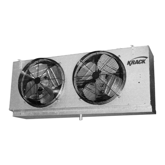
- Page 1 Part Number: E206993_M MK/MV-Medium Profile Series Unit Coolers (E206993_J)
- Page 2 Protection Agency regulations, damage, public safety, noise, and possible This warning does not mean that Hussmann products Federal Clean Air Act (Section 608) for OSHA regulations, and all other federal, state environmental damage. Never leave operating will cause cancer or reproductive harm, or is in and local codes.
- Page 3 It is the installer’s responsibility to reference the refrigeration This warning does not mean that Hussmann drawings supplied for each installation, as products will cause cancer or reproductive directed by the Engineer of Record.
-
Page 4: Table Of Contents
TABLE OF CONTENTS RECEIPT OF EQUIPMENT ____________________________________________________________ 6 INSPECTION __________________________________________________________________ 6 LOSS OF GAS HOLDING CHARGE ___________________________________________________ 6 UNIT INFORMATION AND DIMENSIONS _______________________________________________ 6 MODELS COVERED _____________________________________________________________ 6 UNIT DIMENSIONS _____________________________________________________________ 7 UNIT LOCATION AND MOUNTING ____________________________________________________ 7 UNIT LOCATION _______________________________________________________________ 7 MOUNTING ___________________________________________________________________ 7 PIPING INSTALLATION _____________________________________________________________ 8 DRAIN LINE ___________________________________________________________________ 8... - Page 5 9.2.5 AIR DEFROST _____________________________________________________________ 34 9.2.6 ELECTRIC DEFROST ________________________________________________________ 38 9.2.7 HOT GAS DEFROST ________________________________________________________ 40 CONNECTIVITY (ENABLING SMART ACCESS SETUP) ___________________________________ 42 9.3.1 KE2 STANDARD REMOTE DISPLAY INTERFACE ___________________________________ 42 9.3.2 DIAGNOSTICS MODE _______________________________________________________ 43 9.3.3 POINT TO POINT LAN INTERFACE _____________________________________________ 43 9.3.4 NETWORK INTERFACE ______________________________________________________ 46 SMART ACCESS FROM A WEB BROWSER ___________________________________________ 47...
- Page 6 TABLE OF CHARTS Table 1 UNIT DIMENSIONS ........................... 7 Table 2 SUCTION CONNECTION ........................11 Table 3 MK MEDIUM TEMPERATURE – AIR DEFROST ................. 13 Table 4-1 MK MEDIUM TEMPERATURE – AIR DEFROST ................14 Table 5-1 MK ELECTRIC OR GAS DEFROST ....................15 Table 6 MK ELECTRIC OR GAS DEFROST ......................
- Page 7 TABLE OF FIGURES Figure 1 UNIT DIMENSIONS ......................... 7 Figure 2 MULTIPLE UNIT COOLERS CONTROLLED BY A SINGLE SOLENOID ............. 9 Figure 3 MULTIPLE UNIT COOLERS CONTROLLED BY MULTIPLE SOLENOIDS ..........9 Figure 4 (H) HGE - 3 PIPE HOT GAS COIL WITH ELECTRIC DRAIN PAN DEFROST PIPING ........ 10 Figure 5 (G) HGG - 3 PIPE HOT GAS COIL WITH HOT GAS DRAIN PAN DEFROST PIPING .......
- Page 8 Figure 45 NETWORK SETUP SCREEN ......................51 Figure 46 SETPOINTS SCREEN ........................52 Figure 47 REPLACEMENT PARTS ......................... 63 MK/MV – Medium Profile Series Unit Coolers (E206993_M)
-
Page 9: Receipt Of Equipment
RECEIPT OF EQUIPMENT INSPECTION All equipment should be carefully checked for damage or shortages as soon as it is received. Each shipment should be carefully checked against the bill of lading. If any damage or shortage is evident, a notation must be made on the delivery receipt before it is signed and a claim should then be filed against the freight carrier. -
Page 10: Unit Dimensions
UNIT DIMENSIONS Figure 1 UNIT DIMENSIONS Table 1 UNIT DIMENSIONS Unit Size “A” “B” “C” “D” 1 FAN 38.4 27.0 19.2 2 FAN 63.4 54.0 32.7 3 FAN 92.4 81.0 54.0 46.2 4 FAN 119.4 108.0 54.0 59.7 UNIT LOCATION AND MOUNTING UNIT LOCATION Unit coolers must be located to provide good air circulation to all areas of the cooler. -
Page 11: Piping Installation
PIPING INSTALLATION DRAIN LINE The drain line should be as short and as steeply pitched as possible with a minimum of ¼” drop per running foot. A drain line trap should be installed to prevent warm moist air from migrating through the drain line. -
Page 12: Figure 2 Multiple Unit Coolers Controlled By A Single Solenoid
B. A sufficient number of pressure relief and pressure regulating relief valves may need to be provided based on the system capacity and located such that no stop valve is provided between the relief valves and the parts or section of the system being protected. To properly protect and control systems using pumped liquid overfeed R744, the solenoid, isolation, and pressure relief valves shall be arranged as shown in either Figure 2 or 3, according to the solenoid valve arrangement. -
Page 13: Evacuation And Leak Test
EVACUATION AND LEAK TEST When all refrigeration connections have been completed, the entire system must be tested for leaks and then evacuated. Refer to the instructions provided with your compressor system for information on performing the leak test and evacuation. MK HOT GAS DEFROST PIPING Figure 4 (H) HGE - 3 PIPE HOT GAS COIL WITH ELECTRIC DRAIN PAN DEFROST PIPING Figure 5 (G) HGG - 3 PIPE HOT GAS COIL WITH HOT GAS DRAIN PAN DEFROST PIPING MK/MV –... -
Page 14: Figure 6 (K) Kge - 2 Pipe Reverse Cycle Kool Gas Coil With Electr. Dp Defrost Piping
Figure 6 (K) KGE - 2 PIPE REVERSE CYCLE KOOL GAS COIL WITH ELECTR. DP DEFROST PIPING Figure 7 (K) KGG - 2 PIPE REVERSE CYCLE KOOL GAS COIL WITH KOOL GAS DP DEFROST PIPING Table 2 SUCTION CONNECTION 2, 3 CIRCUITS 4, 5 CIRCUITS 6,7,8,10,13,15 CIRCUITS 20 CIRCUITS... -
Page 15: Refrigerant Distributor Nozzles
REFRIGERANT DISTRIBUTOR NOZZLES Unit coolers are piped using a refrigerant distributor with a changeable nozzle design to equally distribute refrigerant to each circuit of the evaporator coil. Distributor nozzles are included and are packed in individual plastic envelopes along with a retainer ring and instruction card. The instruction card tells what refrigerant the nozzle is to be used with. -
Page 16: Table 3 Mk Medium Temperature - Air Defrost
Table 3 MK MEDIUM TEMPERATURE – AIR DEFROST STANDARD NOZZLE NOZZLE NOZZLE MODEL CIRCUITS R404A R407A R448A MK14A-68 3245 L-3/4 L-1/2 L-3/4 MK14A-94 3060 L-3/4 MK14A-121 2960 L-1-1/2 L-1-1/2 MK24A-188 6120 L-1-1/2 MK24A-242 5920 L-2-1/2 MK34A-363 8880 J-2-1/2 MK44A-484 11840 MK16A-86 2985 L-3/4... -
Page 17: Table 4-1 Mk Medium Temperature - Air Defrost
Table 4 -1 MK MEDIUM TEMPERATURE – AIR DEFROST STANDARD NOZZLE NOZZLE NOZZLE MODEL CIRCUITS R404A R407A R448A MK14A-68 3245 L-3/4 MK14A-94 3060 L-1-1/2 L-1-1/2 MK14A-121 2960 L-1-1/2 MK24A-188 6120 L-2-1/2 L-2-1/2 MK24A-242 5920 MK34A-363 8880 MK44A-484 11840 MK16A-86 2985 L-1-1/2 L-1-1/2 MK16A-118... -
Page 18: Table 5-1 Mk Electric Or Gas Defrost
Table 5-1 MK ELECTRIC OR GAS DEFROST MODEL STANDARD NOZZLE NOZZLE NOZZLE CIRCUITS R404A R407A R448A MK14( )-60 3245 L-3/4 L-1/2 L- 3/4 MK14( )-82 3060 L-3/4 MK14( )-105 2960 L-1-1/2 MK24( )-120 6490 J- 1-1/2 L- 1-1/2 MK24( )-164 6120 J-1-1/2 MK24( )-210... -
Page 19: Table 6 Mk Electric Or Gas Defrost
Table 6 MK ELECTRIC OR GAS DEFROST MODEL STANDARD NOZZLE NOZZLE NOZZLE CIRCUITS R404A R407A R448A MK14( )-60 3245 L-3/4 MK14( )-82 3060 L-1-1/2 L-1-1/2 MK14( )-105 2960 L-1.5 L-1-1/2 MK24( )-120 6490 L-1-1/2 MK24( )-164 6120 J-2.5 MK24( )-210 5920 MK34( )-246 9180... -
Page 20: Expansion Valve
Table 7 MV LOW TEMPERATURE/HIGH VELOCITY - ELECTRIC DEFROST STANDARD NOZZLE NOZZLE NOZZLE MODEL CIRCUITS R404A R407A R448A MV14E-73 4790 L-1-1/2 MV14E-100 4300 L-1-1/2 L-1-1/2 MV14E-128 4130 L-2-1/2 MV24E-146 9580 J-2-1/2 J-2-1/2 MV24E-200 8600 J-2-1/2 MV24E-256 8260 MV34E-300 12900 MV34E-383 12390 MV44E-512 16520... -
Page 21: Table 8 Mk Series - Air Defrost
Expansion valve recommendations are listed in tables 6, 7, and 8. Table 8 MK SERIES – AIR DEFROST 10°F TEMPERATURE DIFFERENCE 15°F TEMPERATURE DIFFERENCE +25°F EVAPORATING TEMPERATURE +25°F EVAPORATING TEMPERATURE MODEL BTUH BTUH R-404A* R407A R408A R-404A* R407A R408A 10°F 15°F T.D. -
Page 22: Table 9 Mk Series - Electric Defrost
Table 9 MK SERIES – ELECTRIC DEFROST 10°F TEMPERATURE DIFFERENCE 10°F TEMPERATURE DIFFERENCE -20°F EVAPORATING TEMPERATURE +20°F EVAPORATING TEMPERATURE BTUH R407A R448A R-404A* BTUH 10°F MODEL R-404A* R407A R448A 10°F T.D. T.D. SBFVE-AA-Z SBFDE- SBFDE-AA-C or ZP40 AAA-Z or EGDE-1/3-C MK-14E-60 6,000 EGVE-3/4-Z... -
Page 23: Table 10 Mv Series Low Temperature - High Velocity
Table 10 MV SERIES – LOW TEMPERATURE – HIGH VELOCITY 10°F TEMPERATURE DIFFERENCE -20°F EVAPORATING TEMPERATURE BTUH R-404A, R407A R448A MODEL R-502, R-507, 10°F T.D. R-402A SBFSE-AA-Z or SBFVE-AA-Z or SBFDE-AA-Z or ZP40 MV14E-73 7,300 EGSE-1/2- Z or EGVE-3/4- Z or EGDE-1/3- Z or ZP40 SBFSE-A-Z or... -
Page 24: Electrical
ELECTRICAL FIELD WIRING WARNING: All power supply to the unit must be shut off before opening any compartments, cleaning or performing maintenance. Field wiring should comply with NEC and local codes. The power supply voltage, phase, and frequency must match what is shown on the unit cooler data plate. The field-wiring compartment is constructed as part of the unit cooler enclosure. -
Page 25: Table 14 Mk Heater Amps
Table 14 MK HEATER AMPS E(EDL) HEATER AMPS P(KGE),H(HGE) DRAIN PAN 230/460V WATTS MODEL MODEL 230/1 230/3 460/3 115/1 230/1 Watt 230V MK14E-60 MK16E-76 10.0 2300 MK14E-82 MK16E-103 10.0 2300 MK14E-105 MK16E-127 12.6 2900 MK24E-120 MK26E-152 19.1 11.1 4400 MK24E-164 MK26E-206 19.1 11.1... -
Page 26: Air Defrost Sequence Of Operation
AIR DEFROST SEQUENCE OF OPERATION SEQUENCE OF OPERATION 1. The unit cooler fan motors are energized, and the fans operate continually. 2. The room thermostat calls for cooling. The liquid solenoid valve opens allowing liquid to flow to the unit cooler. The suction pressure rises and starts the compressor. 3. -
Page 27: Step B: Defrost Cycle
7.1.2 STEP B: DEFROST CYCLE The timer starts defrosting of the evaporator coil at predetermined intervals. A typical setting would be two defrost periods per 24-hour day. Systems using Carbon Dioxide (R744) should defrost at least twice per day. 1. Upon initiation of the defrost cycle, the timer mechanically disconnects power to terminal “4” thus closing the liquid line solenoid valve and shutting off the fan motors. -
Page 28: Figure 10 Defrost Termination Thermostat Location For Carbon Dioxide (R744)
Figure 10 DEFROST TERMINATION THERMOSTAT LOCATION FOR CARBON DIOXIDE (R744) Figure 11 ELECTRIC DEFROST WIRING 208-230/60/1 208-230/60/1 FUSED DISCONNECT (BY OTHERS) DEFROST TIMER TIMER RATED AT 40A RESISTIVE 12A@240V INDUCTIVE EARTH GRD ALTERNATIVE HEATER WIRING ROOM LIQUID MK/MV UNITS 3-4 FAN T'STAT SOLENOID DEFROST... -
Page 29: Figure 12 Electric Defrost Wiring 208-230/60/3
Figure 12 ELECTRIC DEFROST WIRING 208-230/60/3 Figure 13 ELECTRIC DEFROST WIRING 460/60/3 MK/MV – Medium Profile Series Unit Coolers (E206993_M) -
Page 30: Figure 14 Multiple Unit Coolers, Electric Defrost 460/60/3
Figure 14 MULTIPLE UNIT COOLERS, ELECTRIC DEFROST 460/60/3 MK/MV – Medium Profile Series Unit Coolers (E206993_M) -
Page 31: Figure 15 Multiple Unit Coolers, Electric Defrost 208-230/60/3
Figure 15 MULTIPLE UNIT COOLERS, ELECTRIC DEFROST 208-230/60/3 MK/MV – Medium Profile Series Unit Coolers (E206993_M) -
Page 32: Gas Defrost Sequence Of Operation
GAS DEFROST SEQUENCE OF OPERATION The hot gas defrost cycle is time clock initiated and terminated. HGE/HGG 3 PIPE HOT GAS DEFROST Three pipe hot gas defrost systems distribute compressor discharge gas through a separate hot gas line, controlled by a solenoid valve, through a check valve to the refrigerant distributor auxiliary side connection. -
Page 33: Kge/Kgg Reverse Cycle 2 Pipe Kool Gas Defrost
Figure 17 (G) HGG - 3 PIPE HOT GAS COIL AND HOT GAS DRAIN PAN DEFROST WIRING KGE/KGG REVERSE CYCLE 2 PIPE KOOL GAS DEFROST Reverse cycle (2 pipe) defrost systems distribute compressor discharge gas through the suction line during defrost. Defrost condensate flows through the refrigerant distributor auxiliary side connection and a check valve, bypassing the expansion valve and the liquid line solenoid valve into the liquid line which is reduced in pressure. -
Page 34: Figure 18 (P) Kge - 2 Pipe Kool Gas Coil And Electric Drain Pan Defrost Wiring
Figure 18 (P) KGE - 2 PIPE KOOL GAS COIL AND ELECTRIC DRAIN PAN DEFROST WIRING Figure 19 (K) KGG - 2 PIPE KOOL GAS COIL WITH KOOL GAS DRAIN PAN DEFROST WIRING RECOMMENDED (SPST) FAN DELAY THERMOSTAT SETTINGS FOR KGE/HGG ROOM TEMPERATURE RANGE DIFFERENTIAL... -
Page 35: Units With Ke2 Evap Oem Controller
UNITS WITH KE2 EVAP OEM CONTROLLER KE2 Evap OEM controller reduces the energy used by the evaporator coil in refrigeration systems through precise control of superheat, fan management, and demand defrost. SEQUENCE OF OPERATION 1. KE2 Evap OEM creates the evaporator profile when powered up initially. The controller completes a sequence of operational tests of the system (brings the space down to temperature, defrosts the coil, and repeats) to identify a temperature relationship between the coil temperature and space temperature. -
Page 36: Defrost Operation
DEFROST OPERATION KE2 Evap OEM defrost uses a two-tier approach: a. Monitors the coil performance to extend the time between defrosts. b. Monitors the coil’s efficiency (comparing the temperature of the coil to the space temperature) and only calls for defrost when efficiency is less than 90% (incoming data is compared to the evaporator profile data stored in the controller’s memory). -
Page 37: Defrost Settings
9.2.2 DEFROST SETTINGS The “Defrost Mode” parameter enables defrost initiation either based on demand, or by schedule, or by monitoring the compressor run time (duration of refrigeration “ON” cycles). Demand or schedule mode is preferred. Scheduling defrosts evenly across the day, can be achieved by setting following parameters: a. -
Page 38: Figure 22 Air Defrost Controller Wire Diagram
Figure 22 Air Defrost Controller Wire Diagram MK/MV – Medium Profile Series Unit Coolers (E206993_M) -
Page 39: Figure 23 Air Defrost Slave Power Diagram
Figure 23 Air Defrost Slave Power Diagram MK/MV – Medium Profile Series Unit Coolers (E206993_M) -
Page 40: Figure 24 Air Defrost Slave Control Diagram
Figure 24 Air Defrost Slave Control Diagram Note: Master and Slave configuration is only applicable to air defrost units, the control signal from KE2 controller can support up to 16 EC motors. MK/MV – Medium Profile Series Unit Coolers (E206993_M) -
Page 41: Electric Defrost
9.2.6 ELECTRIC DEFROST A traditional defrost controller will power the heaters and keep them on until it receives a signal to terminate based on time or a temperature cut out. One of the issues created with this approach is a fogging effect. -
Page 42: Figure 26 Electric Defrost Controller Wiring Diagram
Figure 26 Electric Defrost Controller Wiring Diagram MK/MV – Medium Profile Series Unit Coolers (E206993_M) -
Page 43: Hot Gas Defrost
9.2.7 HOT GAS DEFROST Notes: 1. The factory default setting for “Defrost Pump Down Time” is 2 minutes for hot gas defrost units. This parameter may be adjusted in the field based on the specific application. (liquid line length, location of liquid line solenoid valve, etc.). Figure 27 Hot Gas Defrost with Electrical Drain Pan Heater Controller Wire Diagram MK/MV –... -
Page 44: Figure 28 Hot Gas Defrost No Electrical Drain Pan Heater Controller Wire Diagram
Figure 28 Hot Gas Defrost No Electrical Drain Pan Heater Controller Wire Diagram MK/MV – Medium Profile Series Unit Coolers (E206993_M) -
Page 45: Connectivity (Enabling Smart Access Setup)
9.3 CONNECTIVITY (ENABLING SMART ACCESS SETUP) Following are the three connection methods to the KE2 Evap OEM controller: a. Establish a connection between KE2 Standard Remote Display w/cable (Part number: 21232) to the display connector on the board. b. Establish a LAN point to point connection using CAT5 cable from PC/Laptop to ethernet connector on the board. -
Page 46: Diagnostics Mode
9.3.1.3 Manual Valve Control Press and hold the Back button & down arrow to put the EEV in Manual Control mode. down arrows will control the valve opening. Enter will advance to the next digit Back will exit this mode. 9.3.1.4 Manual Defrost Pressing and holding the Back... -
Page 47: Figure 31 Network And Sharing Center
Figure 31 NETWORK AND SHARING CENTER Right click “Ethernet” or “Local Area Connection” (Wired) Figure 32 NETWORK CONNECTIONS MK/MV – Medium Profile Series Unit Coolers (E206993_M) -
Page 48: Figure 33 Ethernet Properties
1. Select/Highlight “Internet Protocol Version 4 (TCP/IPv4)”, then choose “Properties” Figure 33 ETHERNET PROPERTIES 2. Select Radio Buttons “Use the following IP address:” Enter the IP address: 10.10.149.1 Enter Subnet mask: 255.255.0.0 Enter Preferred DNS server: 10.10.255.254 Select “OK” Figure 34 INTERNET PROTOCOL VERSION 4 PROPERTIES MK/MV –... -
Page 49: Network Interface
3. As PC/Laptop is now ready to communicate with KE2 Evap OEM controller, close all remaining open windows. 4. Open an internet browser (Mozilla Firefox, Google Chrome, Internet Explorer) and type the controller’s current IP address in the browser. Figure 35 WEB BROWSER Note: The factory default is found on the sticker located on the back of the controller. -
Page 50: Smart Access From A Web Browser
b. Connect the KE2 standard remote display interface to the controllers display connector. c. Press the down arrow to cycle through the Variables menu until “iP1” displays on the screen. Press Enter button to find the value first. Press Enter button again to toggle back to “iP1”... -
Page 51: Login Page
9.4.2 LOGIN PAGE The Login feature prevents unauthorized access to the controller. The user must enter the password to make changes to the Settings page, Network page, and Setpoints page. Figure 26 KE2 EVAP LOGIN PAGE 9.4.3 SETTINGS PAGE The Settings page contains controller configuration for email and web access. It allows installers to customize the MasterView with their company information, update the controller, reset power to the controller, send a test e-mail, clear data collected, and clear alarms. -
Page 52: Network Setup Page
9.4.4 NETWORK SETUP PAGE The network screen enables the user to Bond the KE2 Evap OEM controller for multiple evaporator applications and provides setup for adding controllers to an existing network. Figure 40 KE2 EVAP NETWORK SETTINGS PAGE 9.4.5 SETPOINTS PAGE Allows the user to setup and customize the controller to meet specific application needs. -
Page 53: Graphs
9.4.6 GRAPHS The Graphing Snapshot shows the past seven days of Room Temp and Coil Temp readings, as well as the number and duration of defrost cycles. Figure 42 KE2 EVAP GRAPHS PAGE BONDING When applied to larger systems (up to 8 evaporators attached to the same condenser), the distributed structure KE2 Evap controllers may be bonded over the TCP/IP network to avail following benefits: 1. -
Page 54: Figure 44 Home Page
Setup Instructions 1. Open a browser window and type the IP address of one of the controllers into the browser address field. When the home page is loaded, click Network at the bottom of the screen. Figure 44 HOME PAGE 2. - Page 55 4. The IP address of the other controller(s) will populate under Controllers 2-8. 5. From the Bond State dropdown select Group 1 to bond controller. 6. Click the Save/Group button to view the controllers to be Bonded. Controllers with a blank Bond State will be deleted from the list.
- Page 56 We need to configure the subsequent controllers one at a time, to match the “Multi” settings of the first controller. To accomplish this, enter the IP address of the second controller in the browser and navigate to the Setpoints and complete the steps highlighted above. MK/MV –...
-
Page 57: Start Up
10 START UP 10.1 PRE-STARTUP After the installation is completed, a review of the following items should be performed before the system is placed into operation: Check electrical connections, fan blade set screws, fan motors, guards, and all other fasteners for tightness. -
Page 58: Preventative Maintenance
11 PREVENTATIVE MAINTENANCE A preventative maintenance schedule should be set up as soon as the Unit Cooler is installed. The unit should be inspected periodically for proper operation. WARNING - All power must be disconnected before cleaning. 1. Inspect and clean the drain pan to insure free drainage of condensate. The drain pan should be cleaned regularly with warm water and soap. -
Page 59: Ke2 Oem Evap Troubleshooting Chart
13 KE2 OEM EVAP TROUBLESHOOTING CHART Table 17 KE2 TROUBLESHOOTING Alarm Parameter in VARIABLES menu to Alarm Description Corrective Action Name diagnose further. Blank No LEDs are illuminated Note: While not an alarm condition, the controller may or may not be opera- Display on the display. - Page 60 Q.1.61 November 2018 Page 4 KE2 Evap OEM Alarm Troubleshooting Guide Alarm Parameter in VARIABLES menu to Alarm Description Corrective Action Name diagnose further. Suction ONLY ACTIVE WHEN SUt - T1 SUCTION TEMP • The majority of sensor alarms and inaccurate readings are caused by cut, Tem- AN ELECTRONIC burned, chaffed or otherwise damaged sensor cable.
- Page 61 Q.1.61 November 2018 Page 5 KE2 Evap OEM Alarm Troubleshooting Guide Alarm Parameter in VARIABLES menu to Alarm Description Corrective Action Name diagnose further. Excess Defrost Alarm and Defrost Termination on Time Alarm are closely Excess Exceeds maximum Yellow LED is illuminated. Defrost number of allowable Controller will attempt to continue to...
- Page 62 Q.1.61 November 2018 Page 6 KE2 Evap OEM Alarm Troubleshooting Guide Alarm Parameter in VARIABLES menu to Corrective Action Alarm Description Name diagnose further. High ONLY ACTIVE WHEN Yellow LED is illuminated. • Check the system suction pressure using either the Remote Display (PrS) Superheat AN ELECTRONIC Controller will attempt to continue to...
- Page 63 Q.1.61 November 2018 Page 7 KE2 Evap OEM Alarm Troubleshooting Guide HSH / LSH Corrective Action - Continued HSH / LSH Corrective Action - Continued • Check wiring to the EEV terminal on the KE2 Evap OEM board. Refer below for Low Superheat Alarm Only proper wiring of the KE2-RSV EEV and other common EEV wiring.
- Page 64 Q.1.61 November 2018 Page 9 KE2 Evap OEM Alarm Troubleshooting Guide Alarm Parameter in VARIABLES menu to Alarm Description Corrective Action Name diagnose further. • Verify that the door is closed. Door Open Door is open and room Yellow LED is illuminated. Alarm temperature is 5.0°F de- Controller will attempt to continue to op-...
- Page 65 Q.1.61 November 2018 Page 10 KE2 Evap OEM Alarm Troubleshooting Guide Alarm Parameter in VARIABLES menu to Alarm Description Corrective Action Name diagnose further. External If AU1 (AUX IN 1 MODE) • Troubleshoot the device connected to the auxiliary input to discover why it Alarm 1 = EA1 (EXT ALARM 1): is in alarm condition and resolve the issue.
-
Page 66: Replacement Parts List
14 REPLACEMENT PARTS LIST Listed below are the major replacement parts. When ordering parts it is imperative that you obtain the complete model and serial number of the unit. Figure 47 REPLACEMENT PARTS MK/MV – Medium Profile Series Unit Coolers (E206993_M) -
Page 67: Table 18 Replacement Parts
Table 18 REPLACEMENT PARTS Hussmann Aftermarket Item General Description Options Description Part Number MK PSC MOTOR MK 115/230V 1/4HP 1135RPM 11513N MK 460V 1/4HP 1140RPM 11524N MV PSC MOTOR MV 115/220V 1/3HP 1135RPM E205693 MV 460V 1/3HP 1075RPM E205782 EC 115V-230V 1/3HP 500-1150RPM... - Page 68 2 FAN 460V E201894 3 FAN 115V E201908 3 FAN 230V E201909 3 FAN 460V E201910 4 FAN 115V E201901 4 FAN 230V E201902 4 FAN 460V E201903 DRAIN PAN HEATER BRACKET E102473 SUPPORT BRACKET FACE HEATER SUPPORT BRACKET E105045 BOTTOM HEATER SUPPORT BRACKET E105046...
- Page 69 EGSE-2-C E205985 EGSE-2-ZP E206165 EGVE-1/2-C E205717 EGVE-1-1/2-C E205723 EGVE-1-1/2-ZP40 E205792 EGVE-1-C E205721 EGVE-1-ZP40 E205821 EGVE-2-C E205781 EGVE-2-ZP40 E205735 EGVE-3/4-C E205719 EGVE-3/4-ZP40 E205838 EGVE-3-C E205803 EGVE-3-ZP40 E206058 SBFJE-AA-C E205991 SBFJE-A-C E205992 SBFJE-B-C E205993 SBFJE-C-C E205994 SBFSE-AA-C E206015 SBFSE-A-C E206013 SBFSE-A-ZP E205360 SBFSE-B-C E206014 SBFSE-B-ZP...
- Page 70 MK/MV – Medium Profile Series Unit Coolers (E206993_M) Part Number: E206993_M...
Need help?
Do you have a question about the KRACK MK Series and is the answer not in the manual?
Questions and answers