Advertisement
Table of Contents
- 1 Table of Contents
- 2 Introduction
- 3 Purpose of the Boiler
- 4 The most Important Principles that Must be Strictly Observed
- 5 The Responsibility of the User
- 6 Boiler Equipment
- 7 Technical Data of the Boiler
- 8 Fuel
- 9 Guidelines for the Installation of the Boiler
- 10 Operation and Use of the Boiler
- 11 Causes of Improper Boiler Operation and Their Removal
- 12 Delivery Terms
- 13 Environmental Protection and Boiler Utilisation
- Download this manual
Advertisement
Table of Contents

Subscribe to Our Youtube Channel
Summary of Contents for EKOGREN EG MULTIFUEL 30 kW
- Page 1 Technical and commissioning documentation EG MULTIFUEL 20-80 kW Original instructions / Ver. English Edition X November 2019...
-
Page 4: Table Of Contents
Table of contents 1. INTRODUCTION........................6 2. PURPOSE OF THE BOILER...................... 6 3. THE MOST IMPORTANT PRINCIPLES THAT MUST BE STRICTLY OBSERVED:......7 4. THE RESPONSIBILITY OF THE USER..................7 5. INSTALLER'S RESPONSIBILITY....................8 6. BOILER EQUIPMENT......................8 7. TECHNICAL DATA OF THE BOILER..................9 8. - Page 5 List of Tables Table 1: Boiler equipment Table 2: Basic dimensions of boilers. Table 3: Technical data Table 4 - Required space around the boiler Table 5. Minimum cross sections of supply and exhaust ventilation ducts Table 6. Flow parameters for nominal power Table 7.
-
Page 6: Introduction
1. INTRODUCTION Dear buyer, The Greń company congratulates on the purchase of the EG MULTIFUEL series boiler. Boilers manufactured by our Plant are compliant with the current EU directive, have a test certificate confirming compliance with the requirements of class 5 in accordance with PN-EN 303-5:2012 and CE marking, which is confirmed by the attached Declaration of Conformity. -
Page 7: The Most Important Principles That Must Be Strictly Observed
THE MOST IMPORTANT PRINCIPLES THAT MUST BE STRICTLY OBSERVED: a) The fuel shall be dry and its moisture content shall not exceed 25%. Its granulometry must correspond to the dimensions specified by the manufacturer. In case of doubt about the fuel used, contact the manufacturer. b) It is forbidden to make any changes in the construction and equipment of the boiler. -
Page 8: Boiler Equipment
have received training or additional training in boiler operation as referred to in this manual, please contact GREŃ SP. 5. THE RESPONSIBILITY OF THE INSTALLER Installation of the boiler may only be carried out by a qualified boiler installer, observing and observing all legal regulations, technical standards and good engineering practice. -
Page 9: Technical Data Of The Boiler
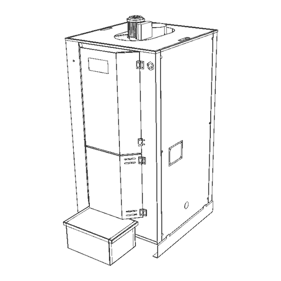
NON-ORIGINAL PARTS, WHICH MANUFACTURED OR RECOMMENDED BY GREENS SP. J. CAUSES THE LOSS OF WARRANTY! 7. TECHNICAL DATA OF THE BOILER The basic dimensions of the boilers are shown in the figure below and in Table 2. Drawing 1: Basic dimensions of the boiler Tabela 1. - Page 10 Table 3: Technical data. Poz. Parameter Unit 20 kW 30 kW 40 kW 60 kW 80 kW Required exhaust mbar gas flow 0,1-0,2 0,1-0,2 0,1-0,2 0,1-0,2 0,15-0,25 Boiler water capacity Temperature of exhaust gases at ̊. C to be completed to be completed from to be completed from to be completed from...
-
Page 11: Fuel
8. FUEL The EG MULTIFUEL multi-fuel boiler is designed to burn biomass, which can be woodchips and wood pellets. Fuels such as sawdust, briquettes, nut shells or fruit stones must not be burned in EG Multifuel boilers. Incineration of the above may void the warranty. Do not use too large pieces of biomass, as this can lead to wear of the feed screw and gearmotors in a short period of time, as well as blockage of the feed system. -
Page 12: Guidelines For The Installation Of The Boiler
9. GUIDELINES FOR THE INSTALLATION OF THE BOILER After the boiler has been delivered to its destination, the completeness of the delivery should be checked (according to Table 1. Boiler equipment) and whether the housing of the appliance and peripheral devices have been damaged during transport. BEFORE PROCEEDING TO INSTALL THE DEVICE IN THE BOILER ROOM, IT IS ABSOLUTELY NECESSARY TO READ THE MANUAL! BEFORE INSTALLING THE FUEL FEEDER (OR TANK), REMOVE THE COVER ON THE SLUICE OPENING. - Page 13 facilitate access to the boiler and to allow for its maintenance, ensure free space around the boiler of at least 400 mm. The boiler must be placed on a non-combustible, thermally insulated surface, the dimensions of which must be at least 200 mm larger than the base of the boiler on each side.
- Page 14 The entrance door to the boiler room should be made of non-combustible materials, The boiler room should be provided with daylight, artificial lighting and water outlet to the outside of the building. ENSURE THAT THERE IS SUFFICIENT AIR SUPPLY TO THE BOILER ROOM. ITS DEFICIENCY THREATENS THE FORMATION OF CARBON MONOXIDE, WHICH IS DANGEROUS TO HEALTH AND LIFE..
- Page 15 Drawing 2 Required space above the boiler Drawing 3. Required space around the boiler Table 4. Required space around the boiler Power 17-30 35-40 45-60...
- Page 16 65-80 9.3. CONNECTION OF THE BOILER TO THE CHIMNEY Boilers in the central heating system must be connected to a separate flue pipe. The method of connection to the flue pipe and its execution should be in accordance with the current regulations in the country where the boiler will be installed.
- Page 17 The connection to the chimney must be made in such a way that it can be easily disconnected in order to gain access to the boiler. The diameter of the chimney inlet and the diameter of the flue pipe must correspond to the dimensions of the flue pipe of the boiler model.
- Page 18 9.4.1. SUPPLY AIR VENTILATION According to the principles of good engineering practice, the supply air ventilation duct should have a cross-section not smaller than 50% of the cross-section of the smoke duct. For boilers of power up to 25kW, the supply ventilation should be carried out through an unclosed opening with a minimum cross-sectional area of 200cm Its opening should be max.
- Page 19 The connection of the boiler to the heating system should be made by means of screw connections, and their cross section must not be reduced below the diameter of the boiler water connection. It is forbidden to connect the boiler with the installation through welded joints.
- Page 20 Boilers are adapted to work at working pressure up to 2. 5 bar (0. 25 MPa). THE INSTALLER'S REGISTRATION WITH THE WARRANTY CARD IS A CONDITION OF ITS VALIDITY. Table 6: Flow parameters for nominal power Boiler output 20kW 30kW 40kW 60kW 80kW...
- Page 21 9.5.1. INSTALLATION OF THE BOILER IN A CLOSED SYSTEM When installing the boiler in a closed circuit heating system, it is necessary to use elements protecting the system against overheating and excessive pressure inside the system. Such installation should include such elements as: diaphragm tank, control and measurement fittings such as thermometer, pressure gauge, etc.
- Page 22 Drawing 4 Diagram of hydraulic connections of the boiler - closed system 9.5.2. INSTALLATION OF THE BOILER IN AN OPEN SYSTEM The installation of the central heating system must be carried out in accordance withthe requirements currently in force in the country of destination. When installing a boiler in Poland, reference should be made to the provisions of PN-EN 12828-A1:2014-05 Heating installations in buildings - design of water central heating systems and the principles of building art and good engineering practice.
- Page 23 EG MULTIFUEL boilers are designed for operation with forced water circulation. Make a gravitational bypass connection for the pump to enable the CO system to be used in the event of a pump failure. When installing the boiler, remember to: ...
- Page 24 Drawing 5: Diagram of hydraulic connections of the boiler - open system 9.5.3. INSTALLATION OF THE BOILER WITH ACCUMULATION BUFFER In some cases, it is necessary to install the boiler in a system in which an accumulation buffer is also installed. The situations in question are. . : ...
- Page 25 Installation with EG MULTIFUEL boiler, whose nominal heating output >=60kW. ATTENTION: PRODUCER REQUIREMENT REQUIREMENTS THE CONNECTION OF EG MULTIFUEL SERIES KETTLES INSTALLATION WITH ACCUMULATING BUFORMANCE FOR ALL ONEYS WHICH NOMINAL POWER ≥ 60kW ! The minimum buffer storage capacity for individual power units required by the manufacturer is shown in the table below: Table 7: Accumulation buffer capacity.
- Page 26 Drawing 6 Diagram of boiler hydraulic connections - closed system with buffer 9.6. CONNECTION OF THE BOILER TO THE ELECTRICAL SYSTEM The EG MULTIFUEL boiler should be connected to an efficient electrical system with a nominal voltage of 230V/50Hz/16A, in accordance with the applicable regulations. The boiler should be connected to a socket equipped with a ground contact.
- Page 27 DEVICES SHOULD BE CONNECTED TO THE MAINS WHEN THE POWER SUPPLY IS SWITCHED OFF, UNDER THE THREAT OF ELECTRIC SHOCK AND LOSS OF HEALTH OR LIFE! 9.6.2. ELECTRICAL CONNECTIONS According to the dashboard manual, the standard electrical connection conditions are 230 Volt (single phase) 50 Hz or 400 Volt (three phases +N) 50 Hz, made in TN-C or TN-S circuit, in accordance with the applicable regulations and standards.
-
Page 28: Operation And Use Of The Boiler
OPERATION AND USE OF THE BOILER The boiler may only be operated by an adult person who has been previously trained by the installer. the scope of training should include information on the construction of the boiler, its operation, operation and emergency procedures. Interference in the automatic boiler operation is forbidden. - Page 29 10.2. THE FIRST START-UP OF THE BOILER. THE FIRST START-UP OF THE BOILER MAY ONLY BE PERFORMED BY THE INSTALLER OR AN EMPLOYEE OF AN AUTHORISED SERVICE COMPANY The following is the scope of activities necessary to carry out during the first start-up of the boiler: ...
- Page 30 Filling the boiler with water should be done through a drain pipe. This should be done slowly to ensure that the air is removed from the system. In the case of open-circuit systems, complete filling takes place when the water flows out of the overflow pipe.
- Page 31 In order to ensure economic fuel consumption, efficient heat exchange and the longest possible service life of the boiler, it is necessary to keep the combustion chamber and heat exchange surface of the exchanger clean. Soot and dust settling on The internal surfaces of the furnace and exchanger significantly reduce the efficiency of the device.
- Page 32 Table 9: Periodic maintenance of the boiler. Operating mode Field of work Daily operation Checking and, if necessary, correcting the combustion process in the appliance controller Weekly Checking the patency of air ducts within the burner. If necessary, they operation should be unblocked.
- Page 33 Figure 7: Removal of ash from the fireplace Figure 8: Location of the cleaning system of the EG MULTIFUE boiler exchanger body cleaner EMPTY THE ASH COLLECTOR BEFORE IT IS COMPLETELY FILLED SO THAT THE ASH SNAIL DOES NOT BECOME DYSFUNCTIONAL AND THE ASH SNAIL DOES NOT DESTROY IT.
- Page 34 FOR SAFETY REASONS, THE ASH MUST BE EMPTIED. WHEN THE BOILER IS SWITCHED OFF AND IT SHOULD NOT BE REMOVED DURING BOILER OPERATION OR IMMEDIATELY AFTER STOPPING THE BOILER OPERATION. Figure 9: Removal of ash from the ash collector ATTENTION! THE ASHES MAY CONTAIN HOT ASHES!
- Page 35 The removal of ash from the ash collector must be carried out regularly in accordance with the following procedure: open and close the ash guard flap, extend the ashtray, empty the ashtray into a suitable container outside the boiler room. 10.5.2.
- Page 36 u) replace the top cover of the boiler, v) install the insulation and seal it tightly with reinforced aluminium tape, w) install the exhaust fan with the turbine, x) reassemble the housing panels, y) check the correct functioning of the device's components, z) activate the device.
- Page 37 g) when installing the exhaust fan, care must be taken to ensure that the connection to the boiler body is tight so that no exhaust fumes can escape at the connection, h) reinstall the exhaust pipe so that the connection is tight. PERFORMANCE OF REPAIR (REMOVAL OF JAM) IN THE FUEL FEEDING SYSTEM, REQUIRING DISASSEMBLY AND ACCESS TO LOCK SHOULD BE DONE WITH THE BOILER SWITCHED OFF!
- Page 38 Once all the steps have been completed, the boiler can be restarted. 10.7. END OF SMOKING After completed heating season or in case of planned boiler shutdown, start the shutdown procedure in the controller and allow for complete burnout of the poured fuel dose into the burner.
- Page 39 it is forbidden to operate a boiler with a low water level in the heating system, when operating the boiler, it is recommended to use personal protective equipment, in particular gloves and safety glasses appropriate to the type of hazard, ...
- Page 40 persons suffering from musculoskeletal system diseases with respect to lifting loads (e. g. pellet bags), whose mass would exceed the standards recommended by the physician, should divide fuel bags into smaller portions when filling the fuel tank. the boiler should be cleaned regularly from soot and dust which adversely affects its efficiency and economy of use.
-
Page 41: Causes Of Improper Boiler Operation And Their Removal
User information: 11. CAUSES OF IMPROPER OPERATION OF THE BOILER AND THEIR REMOVAL Type of fault Possible cause of fault Suggested repair Incorrect settings in the set the parameters in accordance with the Problem with obtaining the controller regulator's operating manual required desired contaminated boiler clean the boiler... -
Page 42: Delivery Terms
Rodzaj usterki Możliwa przyczyna awarii Sugerowana naprawa brak napięcia w sieci elektrycznej sprawdzić napięcie nie podłączona bądź Boiler controller does not switch niepoprawnie podłączona wtyczka sprawdzić podłączenie on after pressing the ON/OFF do gniazdka button poczekać, aż temperatura kotła bezpiecznik główny na tablicy spadnie poniżej 95°C i ponownie rozdzielczej wyłączył... -
Page 43: Environmental Protection And Boiler Utilisation
that it may only be reassembled by a qualified installer. Incorrect connection of the burner and the controller can lead to damage to the heating device. IF THE BOILER IS DAMAGED DURING TRANSPORT, DO NOT INSTALL IT BUT CONTACT THE FACTORY SERVICE. 13. - Page 44 MODEL OF THE BOILER NAMEPLATE...
Need help?
Do you have a question about the EG MULTIFUEL 30 kW and is the answer not in the manual?
Questions and answers